| ... | Regulation | a0c0 |
| ... | 1. Scope | a0c0 |
| ... | 2. Definitions | a0c0 |
| ... | 3. Application for approval | a0c0 |
| ... | 4. Approval | a0c0 |
| ... | 5. Markings | a0c0 |
| ... | 6. Specification in configurations other than REESS charging mode coupled to the power grid | a0c0 |
| ... | 7. Additional specifications in the configuration "REESS charging mode coupled to the power grid" | a0c0 |
| ... | 8. Amendment or extension of a vehicle type approval following electrical/electronic sub-assembly (ESA) addition or substitution | a0c0 |
| ... | a0c0 | |
| ... | 10. Penalties for non-conformity of production | a0c0 |
| ... | 11. Production definitively discontinued | a0c0 |
| ... | 12. Modification and extension of type approval of a vehicle or ESA | a0c0 |
| ... | 13. Transitional provisions | a0c0 |
| ... | 14. Names and addresses of Technical Services conducting approval tests and of Type Approval Authorities | a0c0 |
| ... | Appendix 1 - List of standards referred to in this Regulation | a0c0 |
| ... | Appendix 2 - Vehicle broadband reference limits - Antenna-vehicle separation: 10 m | a0c0 |
| ... | Appendix 3 - Vehicle broadband reference limits - Antenna-vehicle separation: 3 m | a0c0 |
| ... | Appendix 4 - Vehicle narrowband reference limits - Antenna-vehicle separation: 10 m | a0c0 |
| ... | Appendix 5 - Vehicle narrowband reference limits - Antenna-vehicle separation: 3 m | a0c0 |
| ... | Appendix 6 - Electrical/electronic sub-assembly - Broadband reference limits | a0c0 |
| ... | Appendix 7 - Electrical/electronic sub-assembly - Narrowband reference limits | a0c0 |
| ... | Appendix 8 - HV artificial network | a0c0 |
| ... | Annexes | a0c0 |
| ... | 1 Examples of approval marks | a0c0 |
| ... | 2A Information document for type approval of a vehicle with respect to electromagnetic compatibility | a0c0 |
| ... | 2B Information document for type approval of an electric/electronic sub-assembly with respect to electromagnetic compatibility | a0c0 |
| ... | 3A Communication concerning the approval or extension or refusal or withdrawal of approval or production definitively discontinued of a type of vehicle/component/separate technical unit with regard to Regulation No. 10 | a0c0 |
| ... | 3B Communication concerning the approval or extension or refusal or withdrawal of approval or production definitively discontinued of a type of electrical/electronic sub-assembly with regard to Regulation No. 10 | a0c0 |
| ... | 4 Method of measurement of radiated broadband electromagnetic emissions from vehicles | a0c0 |
| ... | Appendix 1 | a0c0 |
| ... | 5 Method of measurement of radiated narrowband electromagnetic emissions from vehicles | a0c0 |
| ... | 6 Method of testing for immunity of vehicles to electromagnetic radiation | a0c0 |
| ... | Appendix 1 | a0c0 |
| ... | 7 Method of measurement of radiated broadband electromagnetic emissions from electrical/electronic sub assemblies (ESAs) | a0c0 |
| ... | Appendix 1 | a0c0 |
| ... | 8 Method of measurement of radiated narrowband electromagnetic emissions from electrical/electronic sub assemblies | a0c0 |
| ... | 9 Method(s) of testing for immunity of electrical/electronic sub-assemblies to electromagnetic radiation | a0c0 |
| ... | Appendix 1 | a0c0 |
| ... | Appendix 2 - Typical TEM cell dimensions | a0c0 |
| ... | Appendix 3 - Absorber chamber test | a0c0 |
| ... | Appendix 4 - BCI test | a0c0 |
| ... | 10 Method(s) of testing for immunity to and emission of transients of electrical/electronic sub-assemblies | a0c0 |
| ... | 11 Method(s) of testing for emission of harmonics generated on AC power lines from vehicle | a0c0 |
| ... | Appendix 1 | a0c0 |
| ... | 12 Method(s) of testing for emission of voltage changes, voltage fluctuations and flicker on AC power lines from vehicle | a0c0 |
| ... | Appendix 1 | a0c0 |
| ... | 13 Method(s) of testing for emission of radiofrequency conducted disturbances on AC or DC power lines from vehicles | a0c0 |
| ... | Appendix 1 | a0c0 |
| ... | 14 Method(s) of testing for emission of radiofrequency conducted disturbances on network and telecommunication access from vehicles | a0c0 |
| ... | Appendix 1 | a0c0 |
| ... | 15 Method of testing for immunity of vehicles to Electrical Fast Transient/Burst disturbances conducted along AC and DC power lines | a0c0 |
| ... | Appendix 1 | a0c0 |
| ... | 16 Method of testing for immunity of vehicles to surges conducted along AC and DC power lines | a0c0 |
| ... | Appendix 1 - Vehicle in configuration "REESS charging mode coupled to the power grid" | a0c0 |
| ... | 17 Method(s) of testing for emission of harmonics generated on AC power lines from an ESA | a0c0 |
| ... | Appendix 1 | a0c0 |
| ... | 18 Method(s) of testing for emission of voltage changes, voltage fluctuations and flicker on AC power lines from an ESA | a0c0 |
| ... | Appendix 1 | a0c0 |
| ... | 19 Method(s) of testing for emission of radiofrequency conducted disturbances on AC or DC power lines from an ESA | a0c0 |
| ... | Appendix 1 | a0c0 |
| ... | 20 Method(s) of testing for emission of radiofrequency conducted disturbances on network and telecommunication access from an ESA | a0c0 |
| ... | 21 Method of testing for immunity of an ESA to Electrical Fast Transient/Burst disturbances conducted along AC and DC power lines | a0c0 |
| ... | Appendix 1 | a0c0 |
| ... | 22 Method of testing for immunity of ESAs to surges conducted along AC and DC power lines | a0c0 |
| ... | Appendix 1 - Appendix 1 - ESA in configuration "REESS charging mode coupled to the power grid" | a0c0 |
| 1. |
|
a0c0 |
| ... | This Regulation applies to: | a0c0 |
| 1.1. |
Vehicles of categories L, M, N and O [1] with regard to electromagnetic compatibility; |
a0c0 |
| 1.2. |
Components and separate technical units intended to be fitted in these vehicles with the limitation given in paragraph 3.2.1. with regard to electromagnetic compatibility. |
a0c0 |
| 1.3. | It covers: | a0c0 |
| ... | (a) Requirements regarding the immunity to radiated and conducted disturbances for functions related to direct control of the vehicle, related to driver, passenger and other road users' protection, related to disturbances, which would cause confusion to the driver or other road users, related to vehicle data bus functionality, related to disturbances, which would affect vehicle statutory data; | a0c0 |
| ... | (b) Requirements regarding the control of unwanted radiated and conducted emissions to protect the intended use of electrical or electronic equipment at own or adjacent vehicles or nearby, and the control of disturbances from accessories that may be retrofitted to the vehicle. | a0c0 |
| ... | (c) Additional requirements for vehicles and ESAs providing coupling systems for charging the REESS regarding the control of emissions and immunity from this connection between vehicle and power grid. | a0c0 |
|
|
As defined in the Consolidated Resolution on the Construction of Vehicles (R.E.3), document ECE/TRANS/WP.29/78/Rev.3, para. 2. |
a0c0 |
| 2. |
|
a0c0 |
| ... | For the purposes of this Regulation: | a0c0 |
| 2.1. | "Electromagnetic compatibility" means the ability of a vehicle or component(s) or separate technical unit(s) to function satisfactorily in its electromagnetic environment without introducing intolerable electromagnetic disturbances to anything in that environment. | a0c0 |
| 2.2. | "Electromagnetic disturbance" means any electromagnetic phenomenon which may degrade the performance of a vehicle or component(s) or separate technical unit(s), or of any other device, unit of equipment or system operated in vicinity of a vehicle. An electromagnetic disturbance may be electromagnetic noise, an unwanted signal or a change in the propagation medium itself. | a0c0 |
| 2.3. |
"Electromagnetic immunity" means the ability of a vehicle or component(s) or separate technical unit(s) to operate without degradation of performance in the presence of (specified) electromagnetic disturbances which includes wanted radio frequency signals from radio transmitters or radiated in-band emissions of industrial-scientific-medical (ISM) apparatus, internal or external to the vehicle. |
a0c0 |
| 2.4. | "Electromagnetic environment" means the totality of electromagnetic phenomena existing at a given location. | a0c0 |
| 2.5. | "Broadband emission" means an emission, which has a bandwidth greater than that of a particular measuring apparatus or receiver (International Special Committee on Radio Interference (CISPR) 25). | a0c0 |
| 2.6. | "Narrowband emission" means an emission which has a bandwidth less than that of a particular measuring apparatus or receiver (CISPR 25). | a0c0 |
| 2.7. | "Electrical/electronic system" means (an) electrical and/or electronic device(s) or set(s) of devices together with any associated electrical connections which form part of a vehicle but which are not intended to be type approved separately from the vehicle. | a0c0 |
| 2.8. |
"Electrical/electronic sub-assembly" (ESA) means an electrical and/or electronic device or set(s) of devices intended to be part of a vehicle, together with any associated electrical connections and wiring, which performs one or more specialized functions. An ESA may be approved at the request of a manufacturer or his authorized representative as either a "component" or a "separate technical unit (STU)". |
a0c0 |
| 2.9. | "Vehicle type" in relation to electromagnetic compatibility includes all vehicles, which do not differ essentially in such respects as: | a0c0 |
| 2.9.1. | The overall size and shape of the engine compartment; | a0c0 |
| 2.9.2. | The general arrangement of the electrical and/or electronic components and the general wiring arrangement; | a0c0 |
| 2.9.3. | The primary material of which the body or shell of the vehicle is constructed (for example, a steel, aluminium or fiberglass body shell). The presence of panels of different material does not change the vehicle type provided the primary material of the body is unchanged. However, such variations shall be notified. | a0c0 |
| 2.10. | An "ESA type" in relation to electromagnetic compatibility means ESAs, which do not differ in such essential respects as: | a0c0 |
| 2.10.1. | The function performed by the ESA; | a0c0 |
| 2.10.2. | The general arrangement of the electrical and/or electronic components, if applicable. | a0c0 |
| 2.11. | "Vehicle wiring harness" means supply voltage, bus system (e.g. CAN), signal or active antenna cables, which are installed by the vehicle manufacturer. | a0c0 |
| 2.12. | "Immunity related functions" are: | a0c0 |
| ... | (a) Functions related to the direct control of the vehicle: | a0c0 |
| ... | (i) By degradation or change in: e.g. engine, gear, brake, suspension, active steering, speed limitation devices; | a0c0 |
| ... | (ii) By affecting drivers position: e.g. seat or steering wheel positioning; | a0c0 |
| ... | (iii) By affecting driver's visibility: e.g. dipped beam, windscreen wiper. | a0c0 |
| ... | (b) Functions related to driver, passenger and other road user protection: | a0c0 |
| ... | (i) E.g. airbag and safety restraint systems. | a0c0 |
| ... | (c) Functions which, when disturbed, cause confusion to the driver or other road users: | a0c0 |
| ... |
(i) Optical disturbances: incorrect operation of e.g. direction indicators, stop lamps, end outline marker lamps, rear position lamp, light bars for emergency system, wrong information from warning indicators, lamps or displays related to functions in subparagraphs (a) or (b) which might be observed in the direct view of the driver; |
a0c0 |
| ... | (ii) Acoustical disturbances: incorrect operation of e.g. anti-theft alarm, horn. | a0c0 |
| ... | (d) Functions related to vehicle data bus functionality: | a0c0 |
| ... | (i) By blocking data transmission on vehicle data bus-systems, which are used to transmit data, required to ensure the correct functioning of other immunity related functions. | a0c0 |
| ... | (e) Functions which when disturbed affect vehicle statutory data: e.g. tachograph, odometer. | a0c0 |
| ... | (f) Function related to charging mode when coupled to the power grid: | a0c0 |
| ... | (i) For vehicle test: by leading to unexpected vehicle motion; | a0c0 |
| ... | (ii) For ESA test: by leading to an incorrect charging condition (e.g. over-current, over-voltage). | a0c0 |
| 2.13. | "REESS" means the rechargeable energy storage system that provides electric energy for electric propulsion of the vehicle. | a0c0 |
| 2.14. | "Coupling system for charging the REESS" means the electrical circuit installed in the vehicle used for charging the REESS. | a0c0 |
| 2.15. | "REESS charging mode coupled to the power grid" means the normal charging operation mode of the vehicle and/or charging system. | a0c0 |
| 3. |
|
a0c0 |
| 3.1. | Approval of a vehicle type | a0c0 |
| 3.1.1. | The application for approval of a vehicle type, with regard to its electromagnetic compatibility, shall be submitted by the vehicle manufacturer. | a0c0 |
| 3.1.2. | A model of information document is shown in Annex 2A. | a0c0 |
| 3.1.3. |
The vehicle manufacturer shall draw up a schedule describing all relevant vehicle electrical/electronic systems or ESAs, body styles, variations in body material, general wiring arrangements, engine variations, left-hand/right-hand drive versions and wheelbase versions. Relevant vehicle electrical/electronic systems or ESAs are those which may emit significant broadband or narrowband radiation and/or those which are involved in immunity related functions of the vehicle (see paragraph 2.12.) and those which provide coupling systems for charging the REESS. |
a0c0 |
| 3.1.4. | A vehicle representative of the type to be approved shall be selected from this schedule by mutual agreement between the manufacturer and the Type Approval Authority. The choice of vehicle shall be based on the electrical/electronic systems offered by the manufacturer. One or more vehicles may be selected from this schedule if it is considered by mutual agreement between the manufacturer and the Type Approval Authority that different electrical/electronic systems are included which are likely to have a significant effect on the vehicle's electromagnetic compatibility compared with the first representative vehicle. | a0c0 |
| 3.1.5. | The choice of the vehicle(s) in conformity with paragraph 3.1.4. above shall be limited to vehicle/electrical/electronic system combinations intended for actual production. | a0c0 |
| 3.1.6. | The manufacturer may supplement the application with a report on tests which have been carried out. Any such data provided may be used by the Type Approval Authority for the purpose of drawing up the communication form for type approval. | a0c0 |
| 3.1.7. |
If the Technical Service responsible for the type approval test carries out the test itself, then a vehicle representative of the type to be approved according to paragraph 3.1.4. above shall be provided. |
a0c0 |
| 3.1.8. | For vehicles of categories M, N, and O, the vehicle manufacturer shall provide a statement of frequency bands, power levels, antenna positions and installation provisions for the installation of radio frequency transmitters (RF-transmitters), even if the vehicle is not equipped with an RF transmitter at time of type approval. This should cover all mobile radio services normally used in vehicles. This information shall be made publicly available following the type approval. | a0c0 |
| ... | Vehicle manufacturers shall provide evidence that vehicle performance is not adversely affected by such transmitter installations. | a0c0 |
| 3.1.9. | Vehicle type approval shall be applied for both REESS and coupling system for charging the REESS as they are considered as electrical/electronic systems. | a0c0 |
| 3.2. | ESA type approval | a0c0 |
| 3.2.1. | Applicability of this Regulation to ESA: | a0c0 |
| ... |
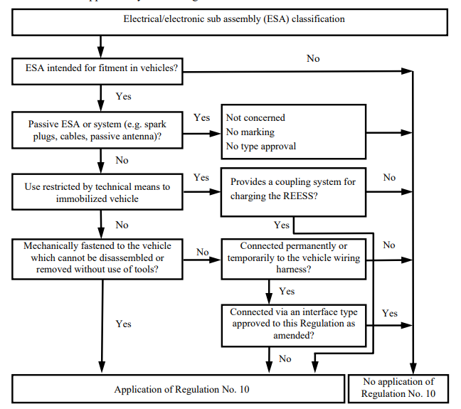
|
a0c0 |
| 3.2.2. | The application for approval of a type of ESA with regard to its electromagnetic compatibility shall be submitted by the vehicle manufacturer or by the manufacturer of the ESA. | a0c0 |
| 3.2.3. | A model of information document is shown in Annex 2B. | a0c0 |
| 3.2.4. | The manufacturer may supplement the application with a report on tests which have been carried out. Any such data provided may be used by the Type Approval Authority for the purpose of drawing up the communication form for type approval. | a0c0 |
| 3.2.5. |
If the Technical Service responsible for the type approval test carries out the test itself, then a sample of the ESA system representative of the type to be approved shall be provided, if necessary, after discussion with the manufacturer on, e.g. possible variations in the layout, number of components, number of sensors. If the Technical Service deems it necessary, it may select a further sample. |
a0c0 |
| 3.2.6. | The sample(s) shall be clearly and indelibly marked with the manufacturer's trade name or mark and the type designation. | a0c0 |
| 3.2.7. | Where applicable, any restrictions on use should be identified. Any such restrictions should be included in Annexes 2B and/or 3B. | a0c0 |
| 3.2.8. |
ESA which are brought to the market as spare parts need no type approval if they are obviously marked as a spare part by an identification number and if they are identical and from the same manufacturer as the corresponding Original Equipment Manufacturer (OEM) part for an already type approved vehicle. |
a0c0 |
| 3.2.9. | Components sold as aftermarket equipment and intended for the installation in motor vehicles need no type approval if they are not related to immunity related functions (see paragraph 2.12.). In this case a declaration shall be issued by the manufacturer that the ESA fulfils the requirements of this Regulation and in particular the limits defined in paragraphs 6.5., 6.6., 6.7., 6.8. and 6.9. of this Regulation. | a0c0 |
| 3.2.10. | In case of an ESA is (part of) a light source, the applicant shall: | a0c0 |
| ... | (a) Specify the approval number according to Regulation No. 37, Regulation No. 99 or Regulation No. 128, granted to this ESA; | a0c0 |
| ... | or | a0c0 |
| ... | (b) Provide a test report by a Technical Service designated by the Type Approval Authority, stating that this ESA is not mechanically interchangeable with any light source according to Regulation No. 37, Regulation No. 99 or Regulation No. 128. | a0c0 |
| 4. |
|
a0c0 |
| 4.1. | Type approval procedures | a0c0 |
| 4.1.1. | Type approval of a vehicle | a0c0 |
| ... | The following alternative procedures for vehicle type approval may be used at the discretion of the vehicle manufacturer. | a0c0 |
| 4.1.1.1. | Approval of a vehicle installation | a0c0 |
| ... | A vehicle installation may be type approved directly by following the provisions laid down in paragraph 6. and, if applicable, in paragraph 7. of this Regulation. If this procedure is chosen by a vehicle manufacturer, no separate testing of electrical/electronic systems or ESAs is required. | a0c0 |
| 4.1.1.2. | Approval of vehicle type by testing of individual ESAs | a0c0 |
| ... | A vehicle manufacturer may obtain approval for the vehicle by demonstrating to the Type Approval Authority that all the relevant (see para. 3.1.3. of this Regulation) electrical/electronic systems or ESAs have been approved in accordance with this Regulation and have been installed in accordance with any conditions attached thereto. | a0c0 |
| 4.1.1.3. | A manufacturer may obtain approval according to this Regulation if the vehicle has no equipment of the type, which is subject to immunity or emission tests. Such approvals do not require testing. | a0c0 |
| 4.1.2. | Type approval of an ESA | a0c0 |
| ... | Type approval may be granted to an ESA to be fitted either to any vehicle type (component approval) or to a specific vehicle type or types requested by the ESA manufacturer (separate technical unit approval). | a0c0 |
| 4.1.3. | ESAs, which are intentional RF transmitters, which have not received type approval in conjunction with a vehicle manufacturer, shall be supplied with suitable installation guidelines. | a0c0 |
| 4.2. | Granting of type approval | a0c0 |
| 4.2.1. | Vehicle | a0c0 |
| 4.2.1.1. | If the representative vehicle fulfils the requirements of paragraph 6. and, if applicable, paragraph 7. of this Regulation, type approval shall be granted. | a0c0 |
| 4.2.1.2. |
A model of communication form for type approval is contained in Annex 3A. |
a0c0 |
| 4.2.2. | ESA | a0c0 |
| 4.2.2.1. | If the representative ESA system(s) fulfil(s) the requirements of paragraph 6. and, if applicable, paragraph 7. of this Regulation, type approval shall be granted. | a0c0 |
| 4.2.2.2. | A model of communication form for type approval is contained in Annex 3B. | a0c0 |
| 4.2.3. |
In order to draw up the communication forms referred to in paragraph 4.2.1.2. or 4.2.2.2. above, the Type Approval Authority of the Contracting Party granting the approval may use a report prepared or approved by a recognized laboratory or in accordance with the provisions of this Regulation. |
a0c0 |
| 4.2.4. | In case of an ESA is (part of) a light source and if the documentation as specified in paragraph 3.2.10. above is missing, approval of this ESA according to Regulation No. 10 shall not be granted. | a0c0 |
| 4.3. |
Approval, or refusal of approval, of a type of vehicle or ESA in accordance with this Regulation shall be notified to the Parties to the Agreement applying this Regulation on a form conforming to the model in Annex 3A or 3B to this Regulation, accompanied by photographs and/or diagrams or drawings on an appropriate scale supplied by the applicant in a format not larger than A4 (210x297 mm) or folded to those dimensions. |
a0c0 |
| 5. |
|
a0c0 |
| 5.1. | An approval number shall be assigned to each vehicle or ESA type approved. The first two digits of this number (at present 05) shall indicate the series of amendments corresponding to the most recent essential technical amendments made to the Regulation at the date of approval. A Contracting Party may not assign the same approval number to another type of vehicle or ESA. | a0c0 |
| 5.2. | Presence of markings | a0c0 |
| 5.2.1. | Vehicle | a0c0 |
| ... |
An approval mark described in paragraph 5.3. below shall be affixed to every vehicle conforming to a type approved under this Regulation. |
a0c0 |
| 5.2.2. | Sub-assembly | a0c0 |
| ... |
An approval mark described in paragraph 5.3. below shall be affixed to every ESA conforming to a type approved under this Regulation. |
a0c0 |
| ... | No marking is required for electrical/electronic systems built into vehicles which are approved as units. | a0c0 |
| 5.3. | An international approval mark shall be affixed, in a conspicuous and easily accessible place specified on the approval communication form, on each vehicle conforming to the type approved under this Regulation. This mark shall comprise: | a0c0 |
| 5.3.1. | A circle containing the letter "E", followed by the distinguishing number of the country granting the approval.[2] | a0c0 |
| 5.3.2. |
The number of this Regulation, followed by the letter "R", a dash and the approval number to the right of the circle specified in paragraph 5.3.1. above. |
a0c0 |
| 5.4. |
An example of the type approval mark is shown in Annex 1 to this Regulation. |
a0c0 |
| 5.5. |
Markings on ESAs in conformity with paragraph 5.3. above need not be visible when the ESA is installed in the vehicle. |
a0c0 |
|
|
The distinguish numbers of the Contracting Parties to the 1958 Agreement are reproduced in Annex 3 to Consolidated Resolution on the Construction of Vehicles (R.E.3), document ECE/TRANS/WP.29/78/Rev.3, Annex 3. |
a0c0 |
| 6. |
|
a0c0 |
| 6.1. | General specifications | a0c0 |
| 6.1.1. | A vehicle and its electrical/electronic system(s) or ESA(s) shall be so designed, constructed and fitted as to enable the vehicle, in normal conditions of use, to comply with the requirements of this Regulation. | a0c0 |
| 6.1.1.1. | A vehicle shall be tested for radiated emissions and for immunity to radiated disturbances. No tests for conducted emissions or immunity to conducted disturbances are required for vehicle type approval. | a0c0 |
| 6.1.1.2. | ESA(s) shall be tested for radiated and conducted emissions, for immunity to radiated and conducted disturbances. | a0c0 |
| 6.1.2. | Before testing, the Technical Service has to prepare a test plan in conjunction with the manufacturer, which contains at least mode of operation, stimulated function(s), monitored function(s), pass/fail criterion(criteria) and intended emissions. | a0c0 |
| 6.2. | Specifications concerning broadband electromagnetic radiation from vehicles | a0c0 |
| 6.2.1. | Method of measurement | a0c0 |
| ... |
The electromagnetic radiation generated by the vehicle representative of its type shall be measured using the method described in Annex 4. The method of measurement shall be defined by the vehicle manufacturer in accordance with the Technical Service. |
a0c0 |
| 6.2.2. | Vehicle broadband type approval limits | a0c0 |
| 6.2.2.1. |
If measurements are made using the method described in Annex 4 using a vehicle-to-antenna spacing of 10.0 ± 0.2 m, the limits shall be 32 dB microvolts/m in the 30 to 75 MHz frequency band and 32 to 43 dB microvolts/m in the 75 to 400 MHz frequency band, this limit increasing logarithmically with frequencies above 75 MHz as shown in Appendix 2 to this Regulation. In the 400 to 1,000 MHz frequency band the limit remains constant at 43 dB microvolts/m. |
a0c0 |
| 6.2.2.2. |
If measurements are made using the method described in Annex 4 using a vehicle-to-antenna spacing of 3.0 ± 0.05 m, the limits shall be 42 dB microvolts/m in the 30 to 75 MHz frequency band and 42 to 53 dB microvolts/m in the 75 to 400 MHz frequency band, this limit increasing logarithmically with frequencies above 75 MHz as shown in Appendix 3 to this Regulation. In the 400 to 1,000 MHz frequency band the limit remains constant at 53 dB microvolts/m. |
a0c0 |
| 6.2.2.3. |
On the vehicle representative of its type, the measured values, expressed in dB microvolts/m shall be below the type approval limits. |
a0c0 |
| 6.3. | Specifications concerning narrowband electromagnetic radiation from vehicles | a0c0 |
| 6.3.1. | Method of measurement | a0c0 |
| ... |
The electromagnetic radiation generated by the vehicle representative of its type shall be measured using the method described in Annex 5. These shall be defined by the vehicle manufacturer in accordance with the Technical Service. |
a0c0 |
| 6.3.2. | Vehicle narrowband type approval limits | a0c0 |
| 6.3.2.1. |
If measurements are made using the method described in Annex 5 using a vehicle-to-antenna spacing of 10.0 ± 0.2 m, the limits shall be 22 dB microvolts/m in the 30 to 75 MHz frequency band and 22 to 33 dB microvolts/m in the 75 to 400 MHz frequency band, this limit increasing logarithmically with frequencies above 75 MHz as shown in Appendix 4 to this Regulation. In the 400 to 1,000 MHz frequency band the limit remains constant at 33 dB microvolts/m. |
a0c0 |
| 6.3.2.2. |
If measurements are made using the method described in Annex 5 using a vehicle-to-antenna spacing of 3.0 ± 0.05 m, the limit shall be 32 dB microvolts/m in the 30 to 75 MHz frequency band and 32 to 43 dB microvolts/m in the 75 to 400 MHz frequency band, this limit increasing logarithmically with frequencies above 75 MHz as shown in Appendix 5 to this Regulation. In the 400 to 1,000 MHz frequency band the limit remains constant at 43 dB microvolts/m. |
a0c0 |
| 6.3.2.3. |
On the vehicle representative of its type, the measured values, expressed in dB microvolts/m, shall be below the type approval limit. |
a0c0 |
| 6.3.2.4. |
Notwithstanding the limits defined in paragraphs 6.3.2.1., 6.3.2.2. and 6.3.2.3. of this Regulation, if, during the initial step described in paragraph 1.3. of Annex 5, the signal strength measured at the vehicle broadcast radio antenna is less than 20 dB micro-volts over the frequency range 76 to 108 MHz measured with an average detector, then the vehicle shall be deemed to comply with the limits for narrowband emissions and no further testing will be required. |
a0c0 |
| 6.4. | Specifications concerning immunity of vehicles to electromagnetic radiation | a0c0 |
| 6.4.1. | Method of testing | a0c0 |
| ... |
The immunity to electromagnetic radiation of the vehicle representative of its type shall be tested by the method described in Annex 6. |
a0c0 |
| 6.4.2. | Vehicle immunity type approval limits | a0c0 |
| 6.4.2.1. |
If tests are made using the method described in Annex 6, the field strength shall be 30 volts/m rms (root mean squared) in over 90 per cent of the 20 to 2,000 MHz frequency band and a minimum of 25 volts/m rms over the whole 20 to 2,000 MHz frequency band. |
a0c0 |
| 6.4.2.2. |
The vehicle representative of its type shall be considered as complying with immunity requirements if, during the tests performed in accordance with Annex 6, there shall be no degradation of performance of "immunity related functions", according to paragraph 2.1. of Annex 6. |
a0c0 |
| 6.5. | Specification concerning broadband electromagnetic interference generated by ESAs | a0c0 |
| 6.5.1. | Method of measurement | a0c0 |
| ... |
The electromagnetic radiation generated by the ESA representative of its type shall be measured by the method described in Annex 7. |
a0c0 |
| 6.5.2. | ESA broadband type approval limits | a0c0 |
| 6.5.2.1. |
If measurements are made using the method described in Annex 7, the limits shall be 62 to 52 dB microvolts/m in the 30 to 75 MHz frequency band, this limit decreasing logarithmically with frequencies above 30 MHz, and 52 to 63 dB microvolts/m in the 75 to 400 MHz band, this limit increasing logarithmically with frequencies above 75 MHz as shown in Appendix 6 to this Regulation. In the 400 to 1,000 MHz frequency band the limit remains constant at 63 dB microvolts/m. |
a0c0 |
| 6.5.2.2. |
On the ESA representative of its type, the measured values, expressed in dB microvolts/m, shall be below the type approval limits. |
a0c0 |
| 6.6. | Specifications concerning narrowband electromagnetic interference generated by ESAs | a0c0 |
| 6.6.1. | Method of measurement | a0c0 |
| ... |
The electromagnetic radiation generated by the ESA representative of its type shall be measured by the method described in Annex 8. |
a0c0 |
| 6.6.2. | ESA narrowband type approval limits | a0c0 |
| 6.6.2.1. |
If measurements are made using the method described in Annex 8, the limits shall be 52 to 42 dB microvolts/m in the 30 to 75 MHz frequency band, this limit decreasing logarithmically with frequencies above 30 MHz, and 42 to 53 dB microvolts/m in the 75 to 400 MHz band, this limit increasing logarithmically with frequencies above 75 MHz as shown in Appendix 7. In the 400 to 1,000 MHz frequency band the limit remains constant at 53 dB microvolts/m. |
a0c0 |
| 6.6.2.2. |
On the ESA representative of its type, the measured value, expressed in dB microvolts/m shall be below the type approval limits. |
a0c0 |
| 6.7. | Specifications concerning the emission of transient conducted disturbances generated by ESAs on 12/24 V supply lines | a0c0 |
| 6.7.1. |
Method of testing The emission of ESA representative of its type shall be tested by the method(s) according to ISO 7637-2 as described in Annex 10 for the levels given in Table 1. |
a0c0 |
| ... |

|
a0c0 |
| 6.8. | Specifications concerning immunity of ESAs to electromagnetic radiation | a0c0 |
| 6.8.1. | Method(s) of testing | a0c0 |
| ... |
The immunity to electromagnetic radiation of the ESA representative of its type shall be tested by the method(s) chosen from those described in Annex 9. |
a0c0 |
| 6.8.2. | ESA immunity type approval limits | a0c0 |
| 6.8.2.1. |
If tests are made using the methods described in Annex 9, the immunity test levels shall be 60 volts/m root-mean-square (rms) for the 150 mm stripline testing method, 15 volts/m rms for the 800 mm stripline testing method, 75 volts/m rms for the Transverse Electromagnetic Mode (TEM) cell testing method, 60 mA rms for the bulk current injection (BCI) testing method and 30 volts/m rms for the free field testing method in over 90 per cent of the 20 to 2,000 MHz frequency band, and to a minimum of 50 volts/m rms for the 150 mm stripline testing method, 12.5 volts/m rms for the 800 mm stripline testing method, 62.5 volts/m rms, for the TEM cell testing method, 50 mA rms for the bulk current injection (BCI) testing method and 25 volts/m rms for the free field testing method over the whole 20 to 2,000 MHz frequency band. |
a0c0 |
| 6.8.2.2. |
The ESA representative of its type shall be considered as complying with immunity requirements if, during the tests performed in accordance with Annex 9, there shall be no degradation of performance of "immunity related functions". |
a0c0 |
| 6.9. | Specifications concerning the immunity of ESAs to transient disturbances conducted along 12/24 V supply lines | a0c0 |
| 6.9.1. | Method of testing | a0c0 |
| ... | The immunity of ESA representative of this type shall be tested by the method(s) according to ISO 7637-2 as described in Annex 10 with the test levels given in Table 2. | a0c0 |
| ... |

|
a0c0 |
| 6.10. | Exceptions | a0c0 |
| 6.10.1. |
Where a vehicle or electrical/electronic system or ESA does not include an electronic oscillator with an operating frequency greater than 9 kHz, it shall be deemed to comply with paragraph 6.3.2. or 6.6.2. and with Annexes 5 and 8. |
a0c0 |
| 6.10.2. |
Vehicles which do not have electrical/electronic systems with "immunity related functions" need not be tested for immunity to radiated disturbances and shall be deemed to comply with paragraph 6.4. and with Annex 6 to this Regulation. |
a0c0 |
| 6.10.3. | ESAs with no immunity related functions need not be tested for immunity to radiated disturbances and shall be deemed to comply with paragraph 6.8. and with Annex 9 to this Regulation. | a0c0 |
| 6.10.4. | Electrostatic discharge | a0c0 |
| ... | For vehicles fitted with tyres, the vehicle body/chassis can be considered to be an electrically isolated structure. Significant electrostatic forces in relation to the vehicle's external environment only occur at the moment of occupant entry into or exit from the vehicle. As the vehicle is stationary at these moments, no type approval test for electrostatic discharge is deemed necessary. | a0c0 |
| 6.10.5. | Emission of transient conducted disturbances generated by ESAs on 12/24 V supply lines. | a0c0 |
| ... | ESAs that are not switched, contain no switches or do not include inductive load need not be tested for transient conducted emission and shall be deemed to comply with paragraph 6.7. | a0c0 |
| 6.10.6. | The loss of function of receivers during the immunity test, when the test signal is within the receiver bandwidth (RF exclusion band) as specified for the specific radio service/product in the harmonized international EMC standard, does not necessarily lead to fail criteria. | a0c0 |
| 6.10.7. | RF transmitters shall be tested in the transmit mode. Wanted emissions (e.g. from RF transmitting systems) within the necessary bandwidth and out of band emissions are disregarded for the purpose of this Regulation. Spurious emissions are subject to this Regulation. | a0c0 |
| 6.10.7.1. |
"Necessary bandwidth": For a given class of emission, the width of the frequency band which is just sufficient to ensure the transmission of information at the rate and with the quality required under specified conditions (Article 1, No. 1.152 of the International Telecommunication Union (ITU) Radio Regulations). |
a0c0 |
| 6.10.7.2. |
"Out-of-band Emissions": Emission on a frequency or frequencies immediately outside the necessary bandwidth which results from the modulation process, but excluding spurious emissions (Article 1, No. 1.144 of the ITU Radio Regulations). |
a0c0 |
| 6.10.7.3. |
"Spurious emission": In every modulation process additional undesired signals exist. They are summarized under the expression "spurious emissions". Spurious emissions are emissions on a frequency or frequencies, which are outside the necessary bandwidth and the level of which may be reduced without affecting the corresponding transmission of information. Spurious emissions include harmonic emissions, parasitic emissions, intermodulation products and frequency conversion products, but exclude out-of-band emissions (Article 1 No. 1.145 of the ITU Radio Regulations). |
a0c0 |
| 7. |
|
a0c0 |
| 7.1. | General specifications | a0c0 |
| 7.1.1. | A vehicle and its electrical/electronic system(s) or ESA(s) shall be so designed, constructed and fitted as to enable the vehicle, in configuration "REESS charging mode coupled to the power grid", to comply with the requirements of this Regulation. | a0c0 |
| 7.1.1.1. | A vehicle in configuration "REESS charging mode coupled to the power grid" shall be tested for radiated emissions, immunity to radiated disturbances, conducted emissions and immunity to conducted disturbances. | a0c0 |
| 7.1.1.2. | ESAs in configuration "REESS charging mode coupled to the power grid" shall be tested for radiated and conducted emissions, for immunity to radiated and conducted disturbances. | a0c0 |
| 7.1.2. | Before testing the Technical Service has to prepare a test plan in conjunction with the manufacturer, for the configuration "REESS charging mode coupled to the power grid" configuration which contains at least mode of operation, stimulated function(s), monitored function(s), pass/fail criterion (criteria) and intended emissions. | a0c0 |
| 7.1.3. | A vehicle in configuration "REESS charging mode coupled to the power grid" should be tested with the charging cable delivered by the manufacturer. In this case, the cable shall be type approved as part of the vehicle. | a0c0 |
| 7.1.4. | Artificial networks | a0c0 |
| ... |
AC Power mains shall be applied to the vehicle / ESA through 50 µH/50 W AN(s) as defined in CISPR 16-1-2 paragraph 4.3. |
a0c0 |
| ... |
DC Power mains shall be applied to the vehicle / ESA through 5 µH/50 W AN(s) as defined in CISPR 25. |
a0c0 |
| ... |
High voltage power line shall be applied to the ESA through a 5 µH/50 W HV-AN(s) as defined in Appendix 8. |
a0c0 |
| 7.2. | Specifications concerning broadband electromagnetic radiation from vehicles | a0c0 |
| 7.2.1. | Method of measurement | a0c0 |
| ... |
The electromagnetic radiation generated by the vehicle representative of its type shall be measured using the method described in Annex 4. The method of measurement shall be defined by the vehicle manufacturer in accordance with the Technical Service. |
a0c0 |
| 7.2.2. | Vehicle broadband type approval limits | a0c0 |
| 7.2.2.1. |
If measurements are made using the method described in Annex 4 using a vehicle-to-antenna spacing of 10.0 ± 0.2 m, the limits shall be 32 dB microvolts/m in the 30 to 75 MHz frequency band and 32 to 43 dB microvolts/m in the 75 to 400 MHz frequency band, this limit increasing logarithmically with frequencies above 75 MHz as shown in Appendix 2. In the 400 to 1,000 MHz frequency band the limit remains constant at 43 dB microvolts/m. |
a0c0 |
| 7.2.2.2. |
If measurements are made using the method described in Annex 4 using a vehicle-to-antenna spacing of 3.0 ± 0.05 m, the limits shall be 42 dB microvolts/m in the 30 to 75 MHz frequency band and 42 to 53 dB microvolts/m in the 75 to 400 MHz frequency band, this limit increasing logarithmically with frequencies above 75 MHz as shown in Appendix 3. In the 400 to 1,000 MHz frequency band the limit remains constant at 53 dB microvolts/m. |
a0c0 |
| ... |
On the vehicle representative of its type, the measured values, expressed in dB microvolts/m shall be below the type approval limits. |
a0c0 |
| 7.3. | Specifications concerning emission of harmonics on AC power lines from vehicles | a0c0 |
| 7.3.1. | Method of measurement | a0c0 |
| ... |
The harmonics emission on AC power lines generated by the vehicle representative of its type shall be measured using the method described in Annex 11. The method of measurement shall be defined by the vehicle manufacturer in accordance with the Technical Service. |
a0c0 |
| 7.3.2. | Vehicle type approval limit | a0c0 |
| 7.3.2.1. | If measurements are made using the method described in Annex 11, the limits for input current ≤ 16 A per phase are those defined in IEC 61000-3-2 and given in Table 3. | a0c0 |
| ... |

|
a0c0 |
| 7.3.2.2. |
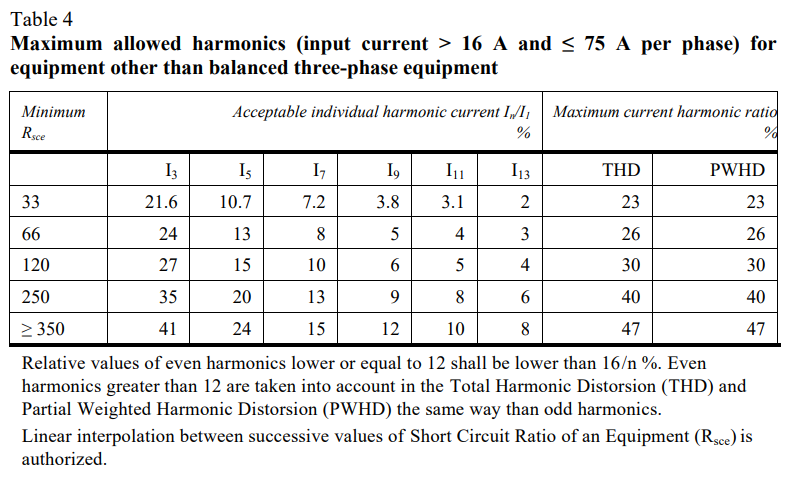
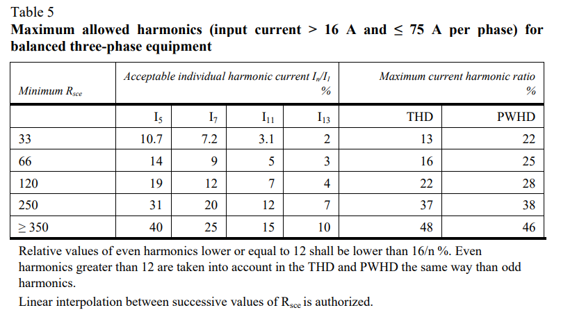
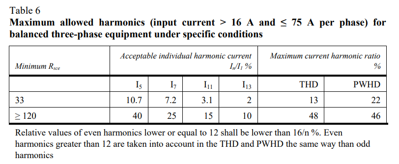
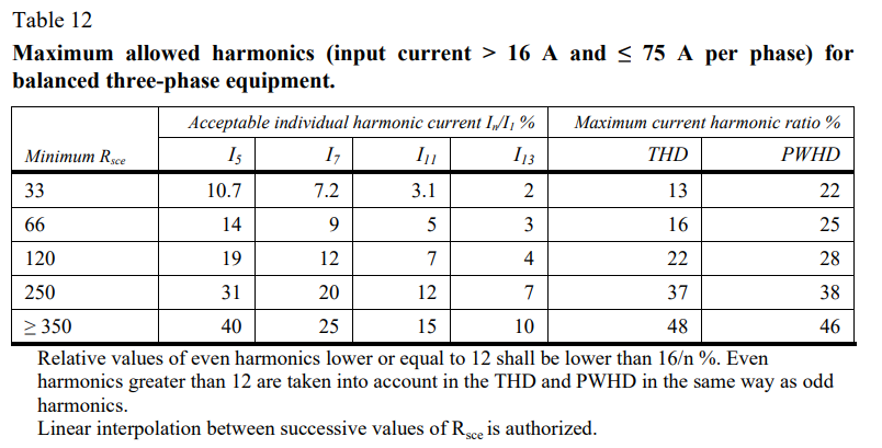
If measurements are made using the method described in Annex 11, the limits for input current > 16 A and ≤ 75 A per phase are those defined in IEC 61000-3-12, and given in given in Table 4, Table 5 and Table 6. |
a0c0 |
| ... |
|
a0c0 |
| ... |
|
a0c0 |
| ... |
|
a0c0 |
| 7.4. | Specifications concerning emission of voltage changes, voltage fluctuations and flicker on AC power lines from vehicles. | a0c0 |
| 7.4.1. | Method of measurement | a0c0 |
| ... |
The emission of voltage changes, voltage fluctuations and flicker on AC power lines generated by the vehicle representative of its type shall be measured using the method described in Annex 12. The method of measurement shall be defined by the vehicle manufacturer in accordance with the Technical Service. |
a0c0 |
| 7.4.2. | Vehicle type approval limit | a0c0 |
| 7.4.2.1. | If measurements are made using the method described in Annex 12, the limits for rated current ≤ 16 A per phase and not subjected to conditional connection are those defined in IEC 61000-3-3, paragraph 5. | a0c0 |
| 7.4.2.2. | If measurements are made using the method described in Annex 12, the limits for rated current > 16 A and ≤ 75 A per phase and subjected to conditional connection are those defined in IEC 61000-3-11, paragraph 5. | a0c0 |
| 7.5. | Specifications concerning emission of radiofrequency conducted disturbances on AC or DC power lines from vehicles | a0c0 |
| 7.5.1. | Method of measurement | a0c0 |
| ... |
The emission of radiofrequency conducted disturbances on AC or DC power lines generated by the vehicle representative of its type shall be measured using the method described in Annex 13. The method of measurement shall be defined by the vehicle manufacturer in accordance with the Technical Service. |
a0c0 |
| 7.5.2. | Vehicle type approval limit | a0c0 |
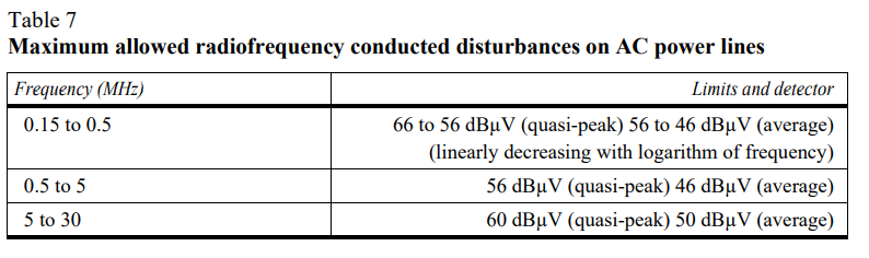
| 7.5.2.1. | If measurements are made using the method described in Annex 13, the limits on AC power lines are those defined in IEC 61000-6-3 and given in Table 7. | a0c0 |
| ... |
|
a0c0 |
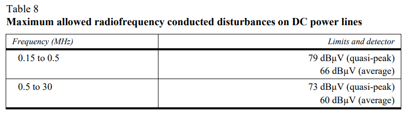
| 7.5.2.2. | If measurements are made using the method described in Annex 13, the limits on DC power lines are those defined in IEC 61000-6-3 and given in Table 8. | a0c0 |
| ... |
|
a0c0 |
| 7.6. | Specifications concerning emission of radiofrequency conducted disturbances on network and telecommunication access from vehicles | a0c0 |
| 7.6.1. | Method of measurement | a0c0 |
| ... |
The emission of radiofrequency conducted disturbances on network and telecommunication access generated by the vehicle representative of its type shall be measured using the method described in Annex 14. The method of measurement shall be defined by the vehicle manufacturer in accordance with the Technical Service. |
a0c0 |
| 7.6.2. | Vehicle type approval limit | a0c0 |
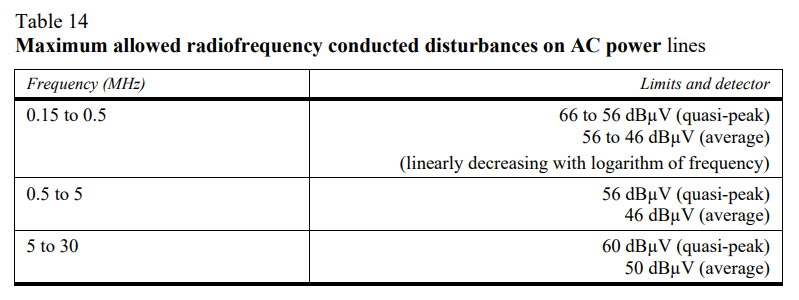
| 7.6.2.1. | If measurements are made using the method described in Annex 14, the limits on network and telecommunication access (telecommunication access as defined in paragraph3.6. of CISPR22) are those defined in IEC 61000-6-3 and given in Table 9. | a0c0 |
| ... |

|
a0c0 |
| 7.7. | Specifications concerning immunity of vehicles to electromagnetic radiation | a0c0 |
| 7.7.1. | Method of testing | a0c0 |
| ... |
The immunity to electromagnetic radiation of the vehicle representative of its type shall be tested by the method described in Annex 6. |
a0c0 |
| 7.7.2. | Vehicle immunity type approval limits | a0c0 |
| 7.7.2.1. |
If tests are made using the method described in Annex 6, the field strength shall be 30 volts/m rms (root mean squared) in over 90 per cent of the 20 to 2,000 MHz frequency band and a minimum of 25 volts/m rms over the whole 20 to 2,000 MHz frequency band. |
a0c0 |
| 7.7.2.2. |
The vehicle representative of its type shall be considered as complying with immunity requirements if, during the tests performed in accordance with Annex 6, there shall be no degradation of performance of "immunity related functions", according to paragraph 2.2. of Annex 6. |
a0c0 |
| 7.8. | Specifications concerning the immunity of vehicles to Electrical Fast Transient/Burst disturbances conducted along AC and DC power lines. | a0c0 |
| 7.8.1. | Method of testing | a0c0 |
| 7.8.1.1. |
The immunity to Electrical Fast Transient/Burst disturbances conducted along AC and DC power lines of the vehicle representative of its type shall be tested by the method described in Annex 15. |
a0c0 |
| 7.8.2. | Vehicle immunity type approval limits | a0c0 |
| 7.8.2.1. |
If tests are made using the methods described in Annex 15, the immunity test levels, for AC or DC power lines, shall be: ±2 kV test voltage in open circuit, with a rise time (Tr) of 5 ns, and a hold time (Th) of 50 ns and a repetition rate of 5 kHz for at least 1 minute. |
a0c0 |
| 7.8.2.2. |
The vehicle representative of its type shall be considered as complying with immunity requirements if, during the tests performed in accordance with Annex 15, there shall be no degradation of performance of "immunity related functions", according to paragraph 2.2. of Annex 6. |
a0c0 |
| 7.9. | Specifications concerning the immunity of vehicles to surge conducted along AC or DC power lines. | a0c0 |
| 7.9.1. | Method of testing | a0c0 |
| 7.9.1.1. |
The immunity to surge conducted along AC/DC power lines of the vehicle representative of its type shall be tested by the method described in Annex 16. |
a0c0 |
| 7.9.2. | Vehicle immunity type approval limits | a0c0 |
| 7.9.2.1. | If tests are made using the methods described in Annex 16, the immunity test levels shall be: | a0c0 |
| ... |
(a) For AC power lines: ±2 kV test voltage in open circuit between line and earth and ±1 kV between lines (pulse 1.2 µs / 50 µs), with a rise time (Tr) of 1.2 µs, and a hold time (Th) of 50 µs. Each surge shall be applied five times with a maximum delay of 1 minute between each pulse. This has to be applied for the following phases: 0, 90, 180 and 270°, |
a0c0 |
| ... |
(b) For DC power lines: ±0.5 kV test voltage in open circuit between line and earth and ±0.5 kV between lines (pulse 1.2 µs / 50 µs) with a rise time (Tr) of 1.2 µs, and a hold time (Th) of 50 µs. Each surge shall be applied five times with a maximum delay of 1 minute. |
a0c0 |
| 7.9.2.2. |
The vehicle representative of its type shall be considered as complying with immunity requirements if, during the tests performed in accordance with Annex 16, there shall be no degradation of performance of "immunity related functions", according to paragraph 2.2. of Annex 6. |
a0c0 |
| 7.10. | Specifications concerning broadband electromagnetic interference caused by ESAs | a0c0 |
| 7.10.1. | Method of measurement | a0c0 |
| ... | The electromagnetic radiation generated by the ESA representative of its type shall be measured by the method described in Annex 7. | a0c0 |
| 7.10.2. | ESA broadband type approval limits | a0c0 |
| 7.10.2.1. |
If measurements are made using the method described in Annex 7, the limits shall be 62 to 52 dB µV/m in the 30 to 75 MHz frequency band, this limit decreasing logarithmically with frequencies above 30 MHz, and 52 to 63 dB µV/m in the 75 to 400 MHz band, this limit increasing logarithmically with frequencies above 75 MHz as shown in Appendix 6. In the 400 to 1,000 MHz frequency band the limit remains constant at 63 dB µV/m. |
a0c0 |
| 7.10.2.2. |
On the ESA representative of its type, the measured values, expressed in dB µV/m, shall be below the type approval limits. |
a0c0 |
| 7.11. | Specifications concerning emission of harmonics on AC power lines from ESAs | a0c0 |
| 7.11.1. | Method of measurement | a0c0 |
| ... | The harmonics emission on AC power lines generated by the ESA representative of its type shall be measured using the method described in Annex 17. The method of measurement shall be defined by the manufacturer in accordance with the Technical Service. | a0c0 |
| 7.11.2. | ESA type approval limit | a0c0 |
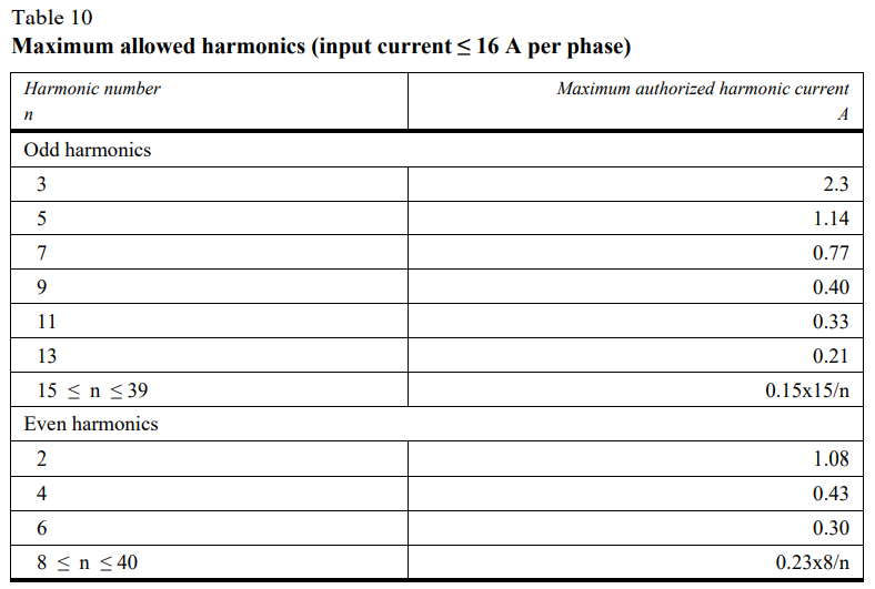
| 7.11.2.1. | If measurements are made using the method described in Annex 17, the limits for input current ≤ 16 A per phase are those defined in IEC 61000-3-2 and given in Table 10. | a0c0 |
| ... |
|
a0c0 |
| 7.11.2.2. |
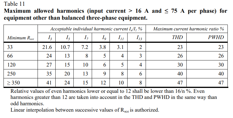
If measurements are made using the method described in Annex 17, the limits for input current > 16 A and ≤ 75 A per phase are those defined in IEC 61000-3-12 and given in Table 11, Table 12 and Table 13. |
a0c0 |
| ... |
|
a0c0 |
| ... |
|
a0c0 |
| ... |

|
a0c0 |
| 7.12. | Specifications concerning emission of voltage changes, voltage fluctuations and flicker on AC power lines from ESAs | a0c0 |
| 7.12.1. | Method of measurement | a0c0 |
| ... | The emission of voltage changes, voltage fluctuations and flicker on AC power lines generated by the ESA representative of its type shall be measured using the method described in Annex 18. The method of measurement shall be defined by the ESA manufacturer in accordance with the Technical Service. | a0c0 |
| 7.12.2. | ESA type approval limit | a0c0 |
| 7.12.2.1. | If measurements are made using the method described in Annex 18, the limits for rated current ≤ 16 A per phase and not subjected to conditional connection are those defined in IEC 61000-3-3, paragraph 5. | a0c0 |
| 7.12.2.2. | If measurements are made using the method described in Annex 18, the limits for rated current > 16 A and ≤ 75 A per phase and subjected to conditional connection are those defined in IEC 61000-3-11, paragraph 5. | a0c0 |
| 7.13. | Specifications concerning emission of radiofrequency conducted disturbances on AC or DC power lines from ESA | a0c0 |
| 7.13.1. | Method of measurement | a0c0 |
| ... | The emission of radiofrequency conducted disturbances on AC or DC power lines generated by the ESA representative of its type shall be measured using the method described in Annex 19. The method of measurement shall be defined by the ESA manufacturer in accordance with the Technical Service. | a0c0 |
| 7.13.2. | ESA type approval limit | a0c0 |
| 7.13.2.1. | If measurements are made using the method described in Annex 19, the limits on AC power lines are those defined in IEC 61000-6-3 and given in Table 14. | a0c0 |
| ... |
|
a0c0 |
| 7.13.2.2. | If measurements are made using the method described in Annex 19, the limits on DC power lines are those defined in IEC 61000-6-3 and given in Table 15. | a0c0 |
| ... |

|
a0c0 |
| 7.14. | Specifications concerning emission of radiofrequency conducted disturbances on network and telecommunication access from ESA | a0c0 |
| 7.14.1. | Method of measurement | a0c0 |
| ... | The emission of radiofrequency conducted disturbances on network and telecommunication access generated by the ESA representative of its type shall be measured using the method described in Annex 20. The method of measurement shall be defined by the ESA manufacturer in accordance with the Technical Service. | a0c0 |
| 7.14.2. | ESA type approval limit | a0c0 |
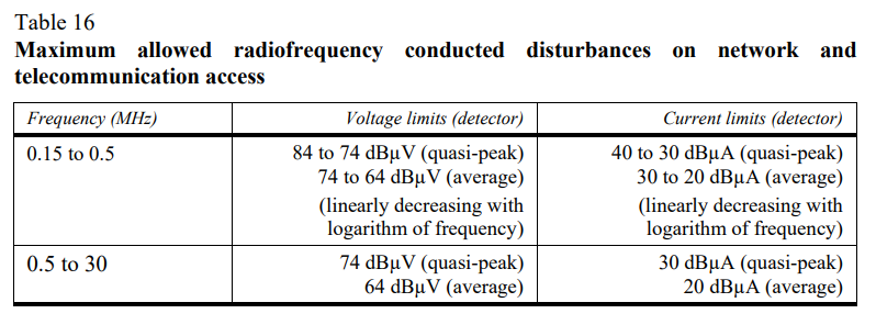
| 7.14.2.1. | If measurements are made using the method described in Annex 20, the limits on network and telecommunication access (telecommunication access as defined in paragraph 3.6 of CISPR22) are those defined in IEC 61000-6-3 and given in Table 16. | a0c0 |
| ... |
|
a0c0 |
| 7.15. | Specifications concerning the immunity of ESAs to electrical fast transient/burst disturbances conducted along AC and DC power lines. | a0c0 |
| 7.15.1. | Method of testing | a0c0 |
| 7.15.1.1. | The immunity to Electrical Fast Transient/Burst disturbances conducted along AC and DC power lines of the ESA representative of its type shall be tested by the method described in Annex 21. | a0c0 |
| 7.15.2. | ESA immunity type approval limits | a0c0 |
| 7.15.2.1. |
If tests are made using the methods described in Annex 21, the immunity test levels, for AC or DC power lines, shall be: ± 2 kV test voltage in open circuit, with a rise time (Tr) of 5 ns, and a hold time (Th) of 50 ns and a repetition rate of 5 kHz for at least 1 minute. |
a0c0 |
| 7.15.2.2. | The ESA representative of its type shall be considered as complying with immunity requirements if, during the tests performed in accordance with Annex 21, there shall be no degradation of performance of "immunity related functions", according to paragraph 2.2. of Annex 9. | a0c0 |
| 7.16. | Specifications concerning the immunity of ESAs to surge conducted along AC or DC power lines | a0c0 |
| 7.16.1. | Method of testing | a0c0 |
| 7.16.1.1. |
The immunity to surge conducted along AC / DC power lines of the ESA representative of its type shall be tested by the method described in Annex 22. |
a0c0 |
| 7.16.2. | ESA immunity type approval limits | a0c0 |
| 7.16.2.1. | If tests are made using the methods described in Annex 22, the immunity test levels shall be: | a0c0 |
| ... |
(a) For AC power lines: ±2 kV test voltage in open circuit between line and earth and ±1 kV between lines (pulse 1.2 µs / 50 µs), with a rise time (Tr) of 1.2 µs, and a hold time (Th) of 50 µs. Each surge shall be applied five times with a maximum delay of 1 minute between each pulse. This has to be applied for the following phases: 0, 90, 180 and 270°, |
a0c0 |
| ... |
(b) For DC power lines: ±0.5 kV test voltage in open circuit between line and earth and ±0.5 kV between lines (pulse 1.2 µs / 50 µs) with a rise time (Tr) of 1.2 µs, and a hold time (Th) of 50 µs. Each surge shall be applied five times with a maximum delay of 1 minute. |
a0c0 |
| 7.16.2.2. | The ESA representative of its type shall be considered as complying with immunity requirements if, during the tests performed in accordance with Annex 22, there shall be no degradation of performance of "immunity related functions", according to paragraph 2.2. of Annex 9. | a0c0 |
| 7.17. | Specifications concerning the emission of transient conducted disturbances generated by ESAs on 12 / 24 V supply lines | a0c0 |
| 7.17.1. | Method of testing | a0c0 |
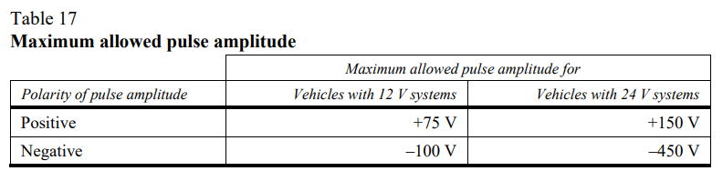
| ... | The emission of ESA representative of its type shall be tested by the method(s) according to ISO 7637-2, as described in Annex 10 for the levels given in Table 17. | a0c0 |
| ... |
|
a0c0 |
| 7.18. | Specifications concerning immunity of ESAs to electromagnetic radiation | a0c0 |
| 7.18.1. | Method(s) of testing | a0c0 |
| ... |
The immunity to electromagnetic radiation of the ESA representative of its type shall be tested by the method(s) chosen from those described in Annex 9. |
a0c0 |
| 7.18.2. | ESA immunity type approval limits | a0c0 |
| 7.18.2.1. |
If tests are made using the methods described in Annex 9, the immunity test levels shall be 60 volts/m rms for the 150 mm stripline testing method, 15 volts/m rms for the 800 mm stripline testing method, 75 volts/m rms for the Transverse Electromagnetic Mode (TEM) cell testing method, 60 mA rms for the Bulk Current Injection (BCI) testing method and 30 volts/m rms for the free field testing method in over 90 per cent of the 20 to 2,000 MHz frequency band, and to a minimum of 50 volts/m rms for the 150 mm stripline testing method, 12.5 volts/m rms for the 800 mm stripline testing method, 62.5 volts/m rms, for the TEM cell testing method, 50 mA rms for the bulk current injection (BCI) testing method and 25 volts/m rms for the free field testing method over the whole 20 to 2,000 MHz frequency band. |
a0c0 |
| 7.18.2.2. | The ESA representative of its type shall be considered as complying with immunity requirements if, during the tests performed in accordance with Annex 9, there shall be no degradation of performance of "immunity related functions". | a0c0 |
| 7.19. | Specifications concerning the immunity of ESAs to transient disturbances conducted along 12 / 24 V supply lines. | a0c0 |
| 7.19.1 | Method of testing | a0c0 |
| ... | The immunity of ESA representative of its type shall be tested by the method(s) according to ISO 7637-2, as described in Annex 10 with the test levels given in Table 18. | a0c0 |
| ... |

|
a0c0 |
| 7.20. | Exceptions | a0c0 |
| 7.20.1. | When there is no direct connection to a telecommunication network which includes telecommunication service additional to the charging communication service, Annex 14 and Annex 20 shall not apply. | a0c0 |
| 7.20.2. | When network and telecommunication access of the vehicle uses power line Transmission (PLT) on its AC/DC power lines, Annex 14 shall not apply. | a0c0 |
| 7.20.3. | When network and telecommunication access of the ESA uses Power Line Transmission (PLT) on its AC/DC power lines, Annex 20 shall not apply. | a0c0 |
| 7.20.4. | Vehicles and / or ESA which are intended to be used in "REESS charging mode coupled to the power grid" in the configuration connected to a DC-charging station with a length of a DC network cable shorter than 30 m do not have to fulfil the requirements of Annex 13, Annex 15, Annex 16, Annex 19, Annex 21 and Annex 22. | a0c0 |
| ... | In this case, the manufacturer shall provide a statement that the vehicle and/or ESA can be used in "REESS charging mode coupled to the power grid" only with cables shorter than 30 m. This information shall be made publicly available following the type approval. | a0c0 |
| 7.20.5. | Vehicles and / or ESA which are intended to be used in "REESS charging mode coupled to the power grid" in the configuration connected to a local / private DC-charging station without additional participants do not have to fulfil requirements of Annexes 13, 15, 16, 19, 21 and 22. | a0c0 |
| ... | In this case, the manufacturer shall provide a statement that the vehicle and / or ESA can be used in "REESS charging mode coupled to the power grid" only with a local/private DC charging station without additional participants. This information shall be made publicly available following the type approval. | a0c0 |
| 8. |
|
a0c0 |
| 8.1. | Where a vehicle manufacturer has obtained type approval for a vehicle installation and wishes to fit an additional or substitutional electrical/electronic system or ESA which has already received approval under this Regulation, and which will be installed in accordance with any conditions attached thereto, the vehicle approval may be extended without further testing. The additional or substitutional electrical/electronic system or ESA shall be considered as part of the vehicle for conformity of production purposes. | a0c0 |
| 8.2. | Where the additional or substitution part(s) has (have) not received approval pursuant to this Regulation, and if testing is considered necessary, the whole vehicle shall be deemed to conform if the new or revised part(s) can be shown to conform to the relevant requirements of paragraph 6. and, if applicable, of paragraph 7. or if, in a comparative test, the new part can be shown not to be likely to adversely affect the conformity of the vehicle type. | a0c0 |
| 8.3. | The addition by a vehicle manufacturer to an approved vehicle of standard domestic or business equipment, other than mobile communication equipment, which conforms to other Regulations, and the installation, substitution or removal of which is according to the recommendations of the equipment and vehicle manufacturers, shall not invalidate the vehicle approval. This shall not preclude vehicle manufacturers fitting communication equipment in accordance with suitable installation guidelines developed by the vehicle manufacturer and/or manufacturer(s) of such communication equipment. The vehicle manufacturer shall provide evidence (if requested by the test authority) that vehicle performance is not adversely affected by such transmitters. This can be a statement that the power levels and installation are such that the immunity levels of this Regulation offer sufficient protection when subject to transmission alone i.e. excluding transmission in conjunction with the tests specified in paragraph 6. This Regulation does not authorize the use of a communication transmitter when other requirements on such equipment or its use apply. | a0c0 |
| 9. |
|
a0c0 |
| ... | The conformity of production procedures shall comply with those set out in the Agreement, Appendix 2 (E/ECE/324-E/ECE/TRANS/505/Rev.2), with the following requirements: | a0c0 |
| 9.1. | Vehicles or components or ESAs approved under this Regulation shall be so manufactured as to conform to the type approved by meeting the requirements set forth in paragraph 6. and, if applicable, in paragraph 7. above. | a0c0 |
| 9.2. |
Conformity of production of the vehicle or component or separate technical unit shall be checked on the basis of the data contained in the communication form(s) for type approval set out in Annex 3A and/or 3B to this Regulation. |
a0c0 |
| 9.3. | If the Type Approval Authority is not satisfied with the checking procedure of the manufacturer, then paragraphs 9.3.1., 9.3.2. and 9.3.3. below shall apply. | a0c0 |
| 9.3.1. | When the conformity of a vehicle, component or ESA taken from the series is being verified, production shall be deemed to conform to the requirements of this Regulation in relation to broadband electromagnetic disturbances and narrowband electromagnetic disturbances if the levels measured do not exceed by more than 4 dB (60 per cent) the reference limits prescribed in paragraphs 6.2.2.1., 6.2.2.2., 6.3.2.1., 6.3.2.2. and, if applicable, paragraphs 7.2.2.1. and 7.2.2.2. for vehicles and paragraphs 6.5.2.1., 6.6.2.1., and, if applicable, paragraph 7.10.2.1. above for ESAs (as appropriate). | a0c0 |
| 9.3.2. | When the conformity of a vehicle, component or ESA taken from the series is being verified, production shall be deemed to conform to the requirements of this Regulation in relation to immunity to electromagnetic radiation if the vehicle ESA does not exhibit any degradation relating to the direct control of the vehicle which could be observed by the driver or other road user when the vehicle is in the state defined in Annex 6, paragraph 4., and is subjected to a field strength, expressed in Volts/m, up to 80 per cent of the reference limits prescribed in paragraph 6.4.2.1., and, if applicable, paragraph 7.7.2.1. for vehicles and paragraph 6.8.2.1. and, if applicable, paragraph 7.18.2.1. for ESAs above. | a0c0 |
| 9.3.3. |
If the conformity of a component, or Separate Technical Unit (STU) taken from the series is being verified, production shall be deemed to conform to the requirements of this Regulation in relation to immunity to conducted disturbances and emission if the component or STU shows no degradation of performance of "immunity related functions" up to levels given in paragraph 6.9.1. and, if applicable, paragraph 7.19.1., and does not exceed the levels given in paragraph 6.7.1. and, if applicable, paragraph 7.17.1. above. |
a0c0 |
| 10. |
|
a0c0 |
| 10.1. | The approval granted in respect of a type of vehicle, component or separate technical unit pursuant to this Regulation may be withdrawn if the requirements laid down in paragraph 6. and, if applicable, paragraph 7. above are not complied with or if the selected vehicles fail to pass the tests provided for in paragraph 6. and, if applicable, paragraph 7. above. | a0c0 |
| 10.2. |
If a Party to the Agreement which applies this Regulation withdraws an approval it has previously granted, it shall forthwith notify the other Contracting Parties applying this Regulation thereof by means of a communication form conforming to the model in Annexes 3A and 3B to this Regulation. |
a0c0 |
| 11. |
|
a0c0 |
| ... |
If the holder of an approval permanently ceases to manufacture a type of vehicle or ESA approved in accordance with this Regulation, he shall so inform the Type Approval Authority which granted the approval, which shall in turn notify the other Parties to the 1958 Agreement which apply this Regulation, by means of a communication form conforming to the model in Annexes 3A and 3B to this Regulation. |
a0c0 |
| 12. |
|
a0c0 |
| 12.1. | Every modification of the vehicle or ESA type shall be notified to the Type Approval Authority which granted approval of the vehicle type. This Authority may then either: | a0c0 |
| 12.1.1. | Consider that the modifications made are unlikely to have an appreciable adverse effect and that in any case the vehicle or ESA still meets the requirements; or | a0c0 |
| 12.1.2. | Require a further test report from the Technical Service responsible for conducting the tests. | a0c0 |
| 12.2. |
Notice of conformation of approval or of refusal of approval, accompanied by particulars of the modifications, shall be communicated by the procedure indicated in paragraph 4. of this Regulation above to the Parties to the Agreement applying this Regulation. |
a0c0 |
| 12.3. |
The Type Approval Authority granting the approval extension shall assign a serial number to the extension and so notify the other Parties to the 1958 Agreement applying this Regulation by means of a communication form conforming to the models in Annexes 3A and 3B to this Regulation. |
a0c0 |
| 13. |
|
a0c0 |
| 13.1. |
As from the official date of entry into force of the 03 series of amendments, no Contracting Party applying this Regulation shall refuse to grant approval under this Regulation as amended by the 03 series of amendments. |
a0c0 |
| 13.2. |
As from 12 months after the date of entry into force of this Regulation, as amended by the 03 series of amendments, Contracting Parties applying this Regulation shall grant approvals only if the vehicle type, component or separate technical unit to be approved meets the requirements of this Regulation as amended by the 03 series of amendments. |
a0c0 |
| 13.3. | Contracting Parties applying this Regulation shall not refuse to grant extensions of approval to the preceding series of amendments to this Regulation. | a0c0 |
| 13.4. |
Starting 48 months after the entry into force of the 03 series of amendments to this Regulation, Contracting Parties applying this Regulation may refuse first national registration (first entry into service) of a vehicle, component or separate technical unit which does not meet the requirements of the 03 series of amendments to this Regulation. |
a0c0 |
| 13.5. |
As from the official date of entry into force of the 04 series of amendments, no Contracting Party applying this Regulation shall refuse to grant type approvals under this Regulation as amended by the 04 series of amendments. |
a0c0 |
| 13.6. | As from 36 months after the official date of entry into force of this Regulation, as amended by the 04 series of amendments, Contracting Parties applying this Regulation shall grant approvals only if the vehicle type, component or separate technical unit, to be approved meets the requirements of this Regulation as amended by the 04 series of amendments. | a0c0 |
| 13.7. | Contracting Parties applying this Regulation shall continue to grant approvals to those types of vehicles or component or separate technical unit type which comply with the requirements of this Regulation as amended by the preceding series of amendments during the 36 months period which follows the date of entry into force of the 04 series of amendments. | a0c0 |
| 13.8. | Until 60 months after the date of entry into force of the 04 series of amendments, no Contracting Parties shall refuse national or regional type approval of a vehicle, component or separate technical unit type approved to the preceding series of amendments to this Regulation. | a0c0 |
| 13.9. | As from 60 months after the date of entry into force of the 04 series of amendments, Contracting Parties applying this Regulation may refuse national or regional type approval and may refuse first registration of a vehicle type, or first entry into service of component or separate technical unit which does not meet the requirements of the 04 series of amendments to this Regulation. | a0c0 |
| 13.10. |
Notwithstanding paragraphs 13.8. and 13.9. above, approvals granted to the preceding series of amendments to the Regulation for vehicle type which are not equipped with a coupling system to charge the REESS, or for component or separate technical unit which doesn't include a coupling part to charge the REESS, shall remain valid and Contracting Parties applying this Regulation shall continue to accept them. |
a0c0 |
| 13.11 | As from 36 months after the date of entry into force of the 05 series of amendments, Contracting Parties applying this Regulation shall grant type approvals only if the vehicle type, component or separate technical unit, to be approved meets the requirements of this Regulation as amended by the 05 series of amendments. | a0c0 |
| 14. |
|
a0c0 |
| ... |
The Parties to the 1958 Agreement applying this Regulation shall communicate to the United Nations Secretariat the names and addresses of the Technical Services conducting approval tests and of the Type Approval Authorities which grant approvals and to which forms certifying approval or extension, refusal or withdrawal of approval, issued in other countries, are to be sent. |
a0c0 |
| ... |
|
a0c0 |
| ... |
|
a0c0 |
| 1. |
CISPR 12 "Vehicles', motorboats' and spark-ignited engine-driven devices' radio disturbance characteristics - Limits and methods of measurement", fifth edition 2001 and Amd1: 2005. |
a0c0 |
| 2. |
CISPR 16-1-4 "Specifications for radio disturbance and immunity measuring apparatus and methods - Part 1: Radio disturbance and immunity measuring apparatus apparatus - Antennas and test sites for radiated disturbances mesaurements", third edition 2010. |
a0c0 |
| 3. |
CISPR 25 "Limits and methods of measurement of radio disturbance characteristics for the protection of receivers used on board vehicles", second edition 2002 and corrigendum 2004. |
a0c0 |
| 4. |
ISO 7637-1 "Road vehicles - Electrical disturbance from conduction and coupling - Part 1: Definitions and general considerations", second edition 2002. |
a0c0 |
| 5. | ISO 7637-2 "Road vehicles - Electrical disturbance from conduction and coupling - Part 2: Electrical transient conduction along supply lines only on vehicles with nominal 12 V or 24 V supply voltage", second edition 2004. | a0c0 |
| 6. |
ISO-EN 17025 "General requirements for the competence of testing and calibration laboratories", second edition 2005 and Corrigendum: 2006. |
a0c0 |
| 7. |
ISO 11451 "Road vehicles - Electrical disturbances by narrowband radiated electromagnetic energy - Vehicle test methods": |
a0c0 |
| ... |
Part 1:General and definitions (ISO 11451-1, third edition 2005 and Amd1: 2008); |
a0c0 |
| ... | Part 2: Off-vehicle radiation source (ISO 11451-2, third edition 2005); | a0c0 |
| ... | Part 4: Bulk current injection (BCI) (ISO 11451-4, first edition 1995). | a0c0 |
| 8. |
ISO 11452 "Road vehicles - Electrical disturbances by narrowband radiated electromagnetic energy - Component test methods": |
a0c0 |
| ... |
Part 1: General and definitions (ISO 11452-1, third edition 2005 and Amd1: 2008); |
a0c0 |
| ... | Part 2: Absorber-lined chamber (ISO 11452-2, second edition 2004); | a0c0 |
| ... | Part 3: Transverse electromagnetic mode (TEM) cell (ISO 11452-3, third edition 2001); | a0c0 |
| ... | Part 4: Bulk current injection (BCI) (ISO 11452-4, third edition 2005 and Corrigendum 1:2009); | a0c0 |
| ... | Part 5: Stripline (ISO 11452-5, second edition 2002). | a0c0 |
| 9. | ITU Radio Regulations, edition 2008. | a0c0 |
| 10. |
IEC 61000-3-2 "Electromagnetic Compatibility (EMC) - Part 3-2 - Limits for harmonic current emissions (equipment input current ≤ 16 A per phase)", edition 3.2 - 2005 + A1: 2008 + A2: 2009. |
a0c0 |
| 11. | IEC 61000-3-3 "Electromagnetic Compatibility (EMC) - Part 3-3 - Limits - Limitation of voltage changes, voltage fluctuations and flicker in public low-voltage systems for equipment with rated current ≤ 16 A per phase and not subjected to conditional connection", edition 2.0 - 2008. | a0c0 |
| 12. | IEC 61000-3-11 "Electromagnetic Compatibility (EMC) - Part 3-11 - Limits - Limitation of voltage changes, voltage fluctuations and flicker in public low-voltage systems - Equipment with rated current ≤ 75 A per phase and subjected to conditional connection", edition 1.0 - 2000. | a0c0 |
| 13. |
IEC 61000-3-12 "Electromagnetic Compatibility (EMC) - Part 3-12 - Limits for harmonic current emissions produced by equipment connected to public low-voltage systems with input current > 16 A and ≤ 75 A per phase", edition 1.0 - 2004. |
a0c0 |
| 14. | IEC 61000-4-4 "Electromagnetic Compatibility (EMC) - Part 4-4 - Testing and measurement techniques - Electrical fast transients/burst immunity test", edition 2.0 - 2004. | a0c0 |
| 15. | IEC 61000-4-5 "Electromagnetic Compatibility (EMC) - Part 4-5 - Testing and measurement techniques - Surge immunity test", edition 2.0 - 2005. | a0c0 |
| 16. | IEC 61000-6-2 "Electromagnetic Compatibility (EMC) - Part 6-2 - Generic standards Immunity for industrial environments", edition 2.0 - 2005. | a0c0 |
| 17. | IEC 61000-6-3 "Electromagnetic Compatibility (EMC) - Part 6-3 - Generic standards Emission standard for residential, commercial and light-industrial environments", edition 2.0 - 2006. | a0c0 |
| 18. |
CISPR 16-2-1 "Specification for radio disturbances and immunity measuring apparatus and methods - Part 2-1 - Methods of measurement of disturbances and immunity - Conducted disturbances measurement", edition 2.0 - 2008. |
a0c0 |
| 19. | CISPR 22 "Information Technology Equipment - Radio disturbances characteristics - Limits and methods of measurement", edition 6.0 - 2008. | a0c0 |
| 20. | CISPR 16-1-2 "Specification for radio disturbance and immunity measuring apparatus and methods - Part 1-2: Radio disturbance and immunity measuring apparatus - Ancillary equipment - Conducted disturbances", edition 1.2: 2006. | a0c0 |
| ... |
|
a0c0 |
| ... |
|
a0c0 |
| ... |

|
a0c0 |
| ... |
|
a0c0 |
| ... |
|
a0c0 |
| ... |
|
a0c0 |
| ... |
|
a0c0 |
| ... |
|
a0c0 |
| ... |

|
a0c0 |
| ... |
|
a0c0 |
| ... |
|
a0c0 |
| ... |

|
a0c0 |
| ... |
|
a0c0 |
| ... |
|
a0c0 |
| ... |

|
a0c0 |
| ... |
|
a0c0 |
| ... |
|
a0c0 |
| ... |
|
a0c0 |
| ... |
|
a0c0 |
| ... |
|
a0c0 |
| ... |
|
a0c0 |
| ... |

|
a0c0 |
| ... |
|
a0c0 |
| A1 |
|
a0c0 |
| A1 |
|
a0c0 |
| A1 |

|
a0c0 |
| A1 | The above approval mark affixed to a vehicle or ESA shows that the vehicle type concerned has, with regard to electromagnetic compatibility, been approved in the Netherlands (E 4) pursuant to Regulation No. 10 under approval No. 05 2439. The approval number indicates that the approval was granted according to the requirements of Regulation No. 10 as amended by the 05 series of amendments. | a0c0 |
| A1 |

|
a0c0 |
| A1 | The above approval mark affixed to a vehicle or ESA shows that the vehicle type concerned has, with regard to electromagnetic compatibility, been approved in the Netherlands (E 4) pursuant to Regulations Nos. 10 and 33.[1] The approval numbers indicate that, at the date when the respective approvals were given, Regulation No. 10 included the 05 series of amendments and Regulation No. 33 was still in its original form. | a0c0 |
|
A1 |
|
a0c0 |
| A2 |
|
a0c0 |
| A2 |
|
a0c0 |
| A2 | The following information shall be supplied in triplicate and shall include a list of contents. | a0c0 |
| A2 | Any drawings shall be supplied in appropriate scale and in sufficient detail on size A4 or in a folder of A4 format. | a0c0 |
| A2 | Photographs, if any, shall show sufficient detail. | a0c0 |
| A2 | If the systems, components or separate technical units have electronic controls, information concerning their performance shall be supplied. | a0c0 |
| A2 | General | a0c0 |
| A2 1. | Make (trade name of manufacturer): | a0c0 |
| A2 2. | Type: | a0c0 |
| A2 3. | Category of vehicle: | a0c0 |
| A2 4. | Name and address of manufacturer: | a0c0 |
| A2 | Name and address of authorised representative, if any: | a0c0 |
| A2 5. | Address(es) of assembly plant(s): | a0c0 |
| A2 | General construction characteristics of the vehicle | a0c0 |
| A2 6. | Photograph(s) and/or drawing(s) of a representative vehicle: | a0c0 |
| A2 7. | Position and arrangement of the engine: | a0c0 |
| A2 | Power plant | a0c0 |
| A2 8. | Manufacturer: | a0c0 |
| A2 9. | Manufacturer's engine code as marked on the engine: | a0c0 |
| A2 10. | Internal combustion engine: | a0c0 |
| A2 11. | Working principle: positive ignition/compression ignition, four-stroke/two stroke[1] | a0c0 |
| A2 12. | Number and arrangement of cylinders: | a0c0 |
| A2 13. | Fuel feed: | a0c0 |
| A2 14. | By fuel injection (compression ignition only): yes/no[1] | a0c0 |
| A2 15. | Electronic control unit: | a0c0 |
| A2 16. | Make(s): | a0c0 |
| A2 17. | Description of the system: | a0c0 |
| A2 18. | By fuel injection (positive ignition only): yes/no[1] | a0c0 |
| A2 19. | Electrical system: | a0c0 |
| A2 20. | Rated voltage: __________________________ V, positive/negative ground[1] | a0c0 |
| A2 21. | Generator: | a0c0 |
| A2 22. | Type: | a0c0 |
| A2 23. | Ignition: | a0c0 |
| A2 24. | Make(s): | a0c0 |
| A2 25. | Type(s): | a0c0 |
| A2 26. | Working principle: | a0c0 |
| A2 27. | LPG fuelling system: yes/no[1] | a0c0 |
| A2 28. | Electronic engine management control unit for LPG fuelling: | a0c0 |
| A2 29. | Make(s): | a0c0 |
| A2 30. | Type(s): | a0c0 |
| A2 31. | NG fuelling system: yes/no[1] | a0c0 |
| A2 32. | Electronic engine management control unit for NG fuelling: | a0c0 |
| A2 33. | Make(s): | a0c0 |
| A2 34. | Type(s): | a0c0 |
| A2 35. | Electric motor: | a0c0 |
| A2 36. | Type (winding, excitation): | a0c0 |
| A2 37. | Operating voltage: | a0c0 |
| A2 |
Gas fuelled engines (in the case of systems laid-out in a different manner, supply equivalent information) |
a0c0 |
| A2 38. | Electronic control unit (ECU): | a0c0 |
| A2 39. | Make(s): | a0c0 |
| A2 40. | Type(s): | a0c0 |
| A2 | Transmission | a0c0 |
| A2 41. | Type (mechanical, hydraulic, electric, etc.): | a0c0 |
| A2 42. | A brief description of the electrical/electronic components (if any): | a0c0 |
| A2 | Suspension | a0c0 |
| A2 43. | A brief description of the electrical/electronic components (if any): | a0c0 |
| A2 44. | A brief description of the electrical/electronic components (if any): | a0c0 |
| A2 | Brakes | a0c0 |
| A2 45. | Anti-lock braking system: yes/no/optional[1] | a0c0 |
| A2 46. | For vehicles with anti-lock systems, description of system operation (including any electronic parts), electric block diagram, hydraulic or pneumatic circuit plan: | a0c0 |
| A2 | Bodywork | a0c0 |
| A2 47. | Type of bodywork: | a0c0 |
| A2 48. | Materials used and methods of construction: | a0c0 |
| A2 49. | Windscreen and other windows: | a0c0 |
| A2 50. | A brief description of the electrical/electronic components (if any) of the window lifting mechanism: | a0c0 |
| A2 51. |
|
a1c0 |
| A2 52. |
A brief description of the |
a1c0 |
| A2 53. | Safety belts and/or other restraint systems: | a0c0 |
| A2 54. | A brief description of the electrical/electronic components (if any): | a0c0 |
| A2 55. | Suppression of radio interference: | a0c0 |
| A2 56. | Description and drawings/photographs of the shapes and constituent materials of the part of the body forming the engine compartment and the part of the passenger compartment nearest to it: | a0c0 |
| A2 57. | Drawings or photographs of the position of the metal components housed in the engine compartment (e.g. heating appliances, spare wheel, air filter, steering mechanism, etc.): | a0c0 |
| A2 58. | Table and drawing of radio interference control equipment: | a0c0 |
| A2 59. | Particulars of the nominal value of the direct current resistance and, in the case of resistive ignition cables, of their nominal resistance per metre: | a0c0 |
| A2 | Lighting and light signalling devices | a0c0 |
| A2 60. | A brief description of electrical/electronic components other than lamps (if any): | a0c0 |
| A2 | Miscellaneous | a0c0 |
| A2 61. | Devices to prevent unauthorised use of the vehicle: | a0c0 |
| A2 62. | A brief description of the electrical/electronic components (if any): | a0c0 |
| A2 63. |
Table of installation and use of RF transmitters in the vehicle(s), if applicable (see paragraph 3.1.8. of this Regulation): |
a0c0 |
| A2 |
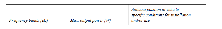
|
a0c0 |
| A2 64. |
Vehicle equipped with 24 GHz short-range radar equipment: yes/no/optional.[1] |
a0c0 |
| A2 | The applicant for type approval shall also supply, where appropriate: | a0c0 |
| A2 Appendix 1: |
A list with make(s) and type(s) of all electrical and/or electronic components concerned by this Regulation (see paragraphs 2.9. and 2.10. of this Regulation) and not previously listed. |
a0c0 |
| A2 Appendix 2: | Schematics or drawing of the general arrangement of electrical and/or electronic components (concerned by this Regulation) and the general wiring harness arrangement. | a0c0 |
| A2 Appendix 3: | Description of vehicle chosen to represent the type: | a0c0 |
| A2 | Body style: | a0c0 |
| A2 | Left or right hand drive: | a0c0 |
| A2 | Wheelbase: | a0c0 |
| A2 Appendix 4: |
Relevant test report(s) supplied by the manufacturer from a test laboratory accredited to ISO 17025 and recognized by the Type Approval Authority for the purpose of drawing up the type approval certificate. |
a0c0 |
| A2 65. | Charger: on board/external/without:[1] | a0c0 |
| A2 66. | Charging current: direct current / alternating current (number of phases/frequency):[1] | a0c0 |
| A2 67. | Maximal nominal current (in each mode if necessary): | a0c0 |
| A2 68. | Nominal charging voltage: | a0c0 |
| A2 69. | Basic vehicle interface functions: ex: L1/L2/L3/N/E/control pilot: | a0c0 |
| A2 70. | Minimum Rsce value (see paragraph 7.3.) | a0c0 |
| A2 71. | Charging cable delivered with the vehicle: yes/no[1] | a0c0 |
| A2 72. | If charging cable delivered with the vehicle: | a0c0 |
| A2 | Length (m) | a0c0 |
| A2 |
Cross sectional area (mm2) |
a0c0 |
|
A2 |
|
a0c0 |
| A2 |
|
a0c0 |
| A2 |
|
a0c0 |
| A2 | The following information, if applicable, shall be supplied in triplicate and shall include a list of contents. Any drawings shall be supplied in appropriate scale and in sufficient detail on size A4 or on a folder of A4 format. Photographs, if any, shall show sufficient detail. | a0c0 |
| A2 | If the systems, components or separate technical units have electronic controls, information concerning their performance shall be supplied. | a0c0 |
| A2 1. | Make (trade name of manufacturer): | a0c0 |
| A2 2. | Type: | a0c0 |
| A2 3. | Means of identification of type, if marked on the component/separate technical unit:[1] | a0c0 |
| A2 3.1. | Location of that marking: | a0c0 |
| A2 4. | Name and address of manufacturer: | a0c0 |
| A2 | Name and address of authorized representative, if any: | a0c0 |
| A2 5. | In the case of components and separate technical units, location and method of affixing of the approval mark: | a0c0 |
| A2 6. | Address(es) of assembly plant(s): | a0c0 |
| A2 7. | This ESA shall be approved as a component/STU[2] | a0c0 |
| A2 8. | Any restrictions of use and conditions for fitting: | a0c0 |
| A2 9. |
Electrical system rated voltage: __ V, positive/negative[2] ground. |
a0c0 |
| A2 Appendix 1: | Description of the ESA chosen to represent the type (electronic block diagram and list of main component constituting the ESA (e.g. make and type of microprocessor, crystal, etc.). | a0c0 |
| A2 Appendix 2: |
Relevant test report(s) supplied by the manufacturer from a test laboratory accredited to ISO 17025 and recognized by the Type Approval Authority for the purpose of drawing up the type approval certificate. |
a0c0 |
| A2 | Only applicable for charging systems: | a0c0 |
| A2 10. | Charger: on board/external[2] | a0c0 |
| A2 11. | Charging current: direct current/alternating current (number of phases/frequency)[2] | a0c0 |
| A2 12. | Maximal nominal current (in each mode if necessary) | a0c0 |
| A2 13. | Nominal charging voltage | a0c0 |
| A2 14. | Basic ESA interface functions: ex. L1/L2/L3/N/PE/control pilot | a0c0 |
| A2 15. | Minimum Rsce value (see paragraph 7.11. of this Regulation) | a0c0 |
|
A2 |
|
a0c0 |
|
A2 |
|
a0c0 |
| A3 |
|
a0c0 |
| A3 |
|
a0c0 |
| A3 | (Maximum format: A4 (210 x 297 mm)) | a0c0 |
| A3 |
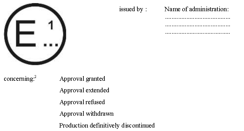
|
a0c0 |
| A3 | of a type of vehicle/component/separate technical unit[2] with regard to Regulation No. 10. | a0c0 |
| A3 | Approval No.:....................Extension No.:.................... | a0c0 |
| A3 1. | Make (trade name of manufacturer): | a0c0 |
| A3 2. | Type: | a0c0 |
| A3 3. | Means of identification of type, if marked on the vehicle/component/separate technical unit[2] | a0c0 |
| A3 3.1. | Location of that marking: | a0c0 |
| A3 4. | Category of vehicle: | a0c0 |
| A3 5. | Name and address of manufacturer: | a0c0 |
| A3 6. | In the case of components and separate technical units, location and method of affixing of the approval mark: | a0c0 |
| A3 7. | Address(es) of assembly plant(s): | a0c0 |
| A3 8. | Additional information (where applicable): See appendix below | a0c0 |
| A3 9. | Technical Service responsible for carrying out the tests: | a0c0 |
| A3 10. | Date of test report: | a0c0 |
| A3 11. | Number of test report: | a0c0 |
| A3 12. | Remarks (if any): See appendix below | a0c0 |
| A3 13. | Place: | a0c0 |
| A3 14. | Date: | a0c0 |
| A3 15. | Signature: | a0c0 |
| A3 16. | The index to the information package lodged with the Approval Authority, which may be obtained on request is attached: | a0c0 |
| A3 17. | Reasons for extension: | a0c0 |
| A3 | Appendix to type approval communication form No......... | a0c0 |
| A3 |
concerning the type approval of a vehicle under Regulation No. 10 |
a0c0 |
| A3 1. | Additional information: | a0c0 |
| A3 2. | Electrical system rated voltage: ..............................................V. pos/neg ground[2] | a0c0 |
| A3 3. | Type of bodywork: | a0c0 |
| A3 4. | List of electronic systems installed in the tested vehicle(s) not limited to the items in the information document: | a0c0 |
| A3 4.1. |
Vehicle equipped with 24 GHz short-range radar equipment: yes/no/optional[2] |
a0c0 |
| A3 5. |
Laboratory accredited to ISO 17025 and recognized by the Approval Authority responsible for carrying out the tests: |
a0c0 |
| A3 6. | Remarks: (e.g. valid for both left-hand drive and right-hand drive vehicles): | a0c0 |
|
A3 |
|
a0c0 |
|
A3 |
|
a0c0 |
| A3 |
|
a0c0 |
| A3 |
|
a0c0 |
| A3 | (Maximum format: A4 (210 x 297 mm)) | a0c0 |
| A3 |
|
a0c0 |
| A3 | of a type of electrical/electronic sub-assembly[2] with regard to Regulation No. 10. | a0c0 |
| A3 1. | Make (trade name of manufacturer): | a0c0 |
| A3 2. | Type and general commercial description(s): | a0c0 |
| A3 3. | Means of identification of type, if marked on the vehicle/component/separate/technical unit[2] | a0c0 |
| A3 3.1. | Location of that marking: | a0c0 |
| A3 4. | Category of vehicle: | a0c0 |
| A3 5. | Name and address of manufacturer: | a0c0 |
| A3 6. | In the case of components and separate technical units, location and method of affixing of the approval mark: | a0c0 |
| A3 7. | Address(es) of assembly plant(s): | a0c0 |
| A3 8. | Additional information (where applicable): See appendix below | a0c0 |
| A3 9. | Technical Service responsible for carrying out the tests: | a0c0 |
| A3 10. | Date of test report: | a0c0 |
| A3 11. | No. of test report: | a0c0 |
| A3 12. | Remarks (if any): See appendix below | a0c0 |
| A3 13. | Place: | a0c0 |
| A3 14. | Date: | a0c0 |
| A3 15. | Signature: | a0c0 |
| A3 16. | The index to the information package lodged with the Approval Authority, which may be obtained on request, is attached: . | a0c0 |
| A3 17. | Reasons for extension: | a0c0 |
| A3 | Appendix to type approval communication form No........ | a0c0 |
| A3 | concerning the type approval of an electrical/electronic | a0c0 |
| A3 | sub-assembly under Regulation No. 10 | a0c0 |
| A3 1. | Additional information: | a0c0 |
| A3 1.1. | Electrical system rated voltage: ...................................................V. pos/neg ground[2] | a0c0 |
| A3 1.2. | This ESA can be used on any vehicle type with the following restrictions: | a0c0 |
| A3 1.2.1. | Installation conditions, if any: | a0c0 |
| A3 1.3. | This ESA can be used only on the following vehicle types: | a0c0 |
| A3 1.3.1. | Installation conditions, if any: | a0c0 |
| A3 1.4. |
The specific test method(s) used and the frequency ranges covered to determine immunity were: (Please specify precise method used from Annex 9): |
a0c0 |
| A3 1.5. | Laboratory accredited to ISO 17025 and recognized by the Approval Authority responsible for carrying out the tests: | a0c0 |
| A3 2. | Remarks: | a0c0 |
| A4 |
|
a0c0 |
| A4 |
|
a0c0 |
| A4 1. | General | a0c0 |
| A4 1.1. | The test method described in this annex shall only be applied to vehicles. This method concerns both configurations of the vehicle: | a0c0 |
| A4 | (a) Other than "REESS charging mode coupled to the power grid". | a0c0 |
| A4 | (b) "REESS charging mode coupled to the power grid" | a0c0 |
| A4 1.2. | Test method | a0c0 |
| A4 | This test is intended to measure the broadband emissions generated by electrical or electronic systems fitted to the vehicle (e.g. ignition system or electric motors). | a0c0 |
| A4 |
If not otherwise stated in this annex the test shall be performed according to CISPR 12. |
a0c0 |
| A4 2. | Vehicle state during tests | a0c0 |
| A4 2.1. | Vehicle in configuration other than "REESS charging mode coupled to the power grid". | a0c0 |
| A4 2.1.1. | Engine | a0c0 |
| A4 |
The engine shall be in operation according to CISPR 12. |
a0c0 |
| A4 2.1.2. | Other vehicle systems | a0c0 |
| A4 | All equipment capable of generating broadband emissions which can be switched on permanently by the driver or passenger should be in operation in maximum load, e.g. wiper motors or fans. The horn and electric window motors are excluded because they are not used continuously. | a0c0 |
| A4 2.2. | Vehicle in configuration "REESS charging mode coupled to the power grid". | a0c0 |
| A4 | The state of charge (SOC) of the traction battery shall be kept between 20 per cent and 80 per cent of the maximum SOC during the whole frequency range measurement (this may lead to split the measurement into different sub-bands with the need to discharge the vehicle's traction battery before starting the next sub-bands). If the current consumption can be adjusted, then the current shall be set to at least 80 per cent of its nominal value. | a0c0 |
| A4 | The test set-up for the connection of the vehicle in configuration "REESS charging mode coupled to the power grid" is shown in Figures 3a to 3h (depending of AC or DC power charging mode, location of charging plug and charging with or without communication) of Appendix 1 to this annex. | a0c0 |
| A4 2.3. | Charging station / Power mains | a0c0 |
| A4 | The charging station may be placed either in the test location or outside the test location. | a0c0 |
| A4 | Note 1: If the communication between the vehicle and the charging station could be simulated, the charging station may be replaced by the supply from power mains. | a0c0 |
| A4 | In both case, duplicated power mains and communication lines socket(s) shall be placed in the test location with the following conditions: | a0c0 |
| A4 | (a) It shall be placed on the ground plane. | a0c0 |
| A4 | (b) The length of the harness between the power mains/communication lines socket and the AN(s)/IS(s) shall be kept as short as possible. | a0c0 |
| A4 | (c) The harness between the power mains/communication lines socket and the AN(s)/IS(s) shall be placed as close as possible to the ground plane. | a0c0 |
| A4 | Note 2: The power mains and communication lines socket(s) should be filtered. | a0c0 |
| A4 | If the charging station is placed inside the test location then the harness between charging station and the power mains / communication lines socket shall be placed with the following conditions: | a0c0 |
| A4 | (a) The harness on charging station side shall hang vertically down to the ground plane. | a0c0 |
| A4 | (b) The extraneous length shall be placed as close as possible to the ground plane and "Z-folded" if necessary. | a0c0 |
| A4 | Note 3: The charging station should be placed outside the beam width of the receiving antenna. | a0c0 |
| A4 2.4 | Artificial networks | a0c0 |
| A4 | The AN(s) shall be mounted directly on the ground plane. The cases of the AN(s) shall be bonded to the ground plane. | a0c0 |
| A4 | The measuring port of each AN shall be terminated with a 50 Ω load. | a0c0 |
| A4 | The AN shall be placed as defined in Figures 3a to 3h. | a0c0 |
| A4 2.5 | Impedance stabilization | a0c0 |
| A4 | Communication lines shall be applied to the vehicle through IS(s). | a0c0 |
| A4 | The impedance stabilization (IS) to be connected in the network and communication cables is defined in CISPR 22, paragraph 9.6.2. | a0c0 |
| A4 | The IS(s) shall be mounted directly on the ground plane. The case of the IS(s) shall be bonded to the ground plane. | a0c0 |
| A4 |
The measuring port of each IS shall be terminated with a 50 Ω load. |
a0c0 |
| A4 | The IS shall be placed as defined in Figures 3e to 3h. | a0c0 |
| A4 2.6 | Power charging / communication cable | a0c0 |
| A4 | The power charging / communication cable shall be placed in a straight line between the AN(s) / IS(s) and the vehicle charging plug. The projected cable length shall be 0.8 m (+0.2/-0 m). | a0c0 |
| A4 | If the length of the cable is longer than 1 m, the extraneous length shall be "Z-folded" in less than 0.5 m width. | a0c0 |
| A4 | The charging / communication cable at vehicle side shall hang vertically at a distance of 100 mm (+200/-0 mm) from the vehicle body. | a0c0 |
| A4 |
The whole cable shall be placed on a non-conductive, low relative permittivity (dielectric-constant) material (εr ≤ 1.4), at 100 mm (±25 mm) above the ground plane. |
a0c0 |
| A4 3. | Measuring location | a0c0 |
| A4 3.1. | As an alternative to the requirements of CISPR 12 for vehicles of category L, the test surface may be any location that fulfils the conditions shown in the Figure of the appendix to this annex. In this case the measuring equipment shall lie outside the part shown in Figure 1 of Appendix 1 to this annex. | a0c0 |
| A4 3.2. | Enclosed test facilities may be used if correlation can be shown between the results obtained in the enclosed test facility and those obtained at an outdoor site. Enclosed test facilities do not need to meet the dimensional requirements of the outdoor site other than the distance from the antenna to the vehicle and the height of the antenna. | a0c0 |
| A4 4. | Test requirements | a0c0 |
| A4 4.1. | The limits apply throughout the frequency range 30 to 1,000 MHz for measurements performed in a semi anechoic chamber or an outdoor test site. | a0c0 |
| A4 4.2. | Measurements can be performed with either quasi-peak or peak detectors. The limits given in paragraphs 6.2. and 6.5. of this Regulation are for quasi-peak detectors. If peak detectors are used a correction factor of 20 dB as defined in CISPR 12 shall be applied. | a0c0 |
| A4 4.3. | The measurements shall be performed with a spectrum analyser or a scanning receiver. The parameters to be used are defined in Table 1 and Table 2. | a0c0 |
| A4 |
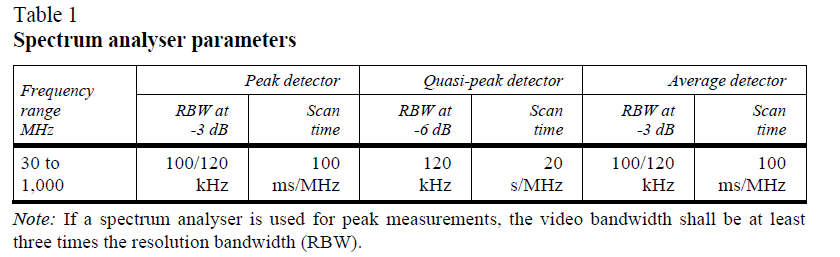
|
a0c0 |
| A4 |

|
a0c0 |
| A4 4.4. | Measurements | a0c0 |
| A4 | The Technical Service shall perform the test at the intervals specified in the CISPR 12 standard throughout the frequency range 30 to 1,000 MHz. | a0c0 |
| A4 |
Alternatively, if the manufacturer provides measurement data for the whole frequency band from a test laboratory accredited to the applicable parts of ISO 17025 and recognized by the Type Approval Authority, the Technical Service may divide the frequency range in 14 frequency bands 30–34, 34–45, 45–60, 60–80, 80–100, 100–130, 130–170, 170–225, 225–300, 300–400, 400–525, 525–700, 700–850 and 850–1,000 MHz and perform tests at the 14 frequencies giving the highest emission levels within each band to confirm that the vehicle meets the requirements of this annex. |
a0c0 |
| A4 | In the event that the limit is exceeded during the test, investigations shall be made to ensure that this is due to the vehicle and not to background radiation. | a0c0 |
| A4 4.5 | Readings | a0c0 |
| A4 | The maximum of the readings relative to the limit (horizontal and vertical polarization and antenna location on the left and right-hand sides of the vehicle) in each of the 14 frequency bands shall be taken as the characteristic reading at the frequency at which the measurements were made. | a0c0 |
| A4 |
|
a0c0 |
| A4 | Figure 1 | a0c0 |
| A4 |
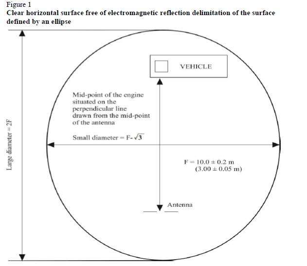
|
a0c0 |
| A4 | Figure 2 | a0c0 |
| A4 | Position of antenna in relation to the vehicle: | a0c0 |
| A4 | Figure 2a | a0c0 |
| A4 | Dipole antenna in position to measure the vertical radiation components | a0c0 |
| A4 |
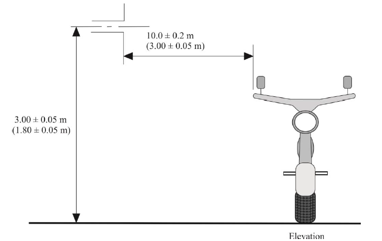
|
a0c0 |
| A4 | Figure 2b | a0c0 |
| A4 | Dipole antenna in position to measure the horizontal radiation components | a0c0 |
| A4 |
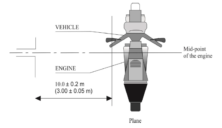
|
a0c0 |
| A4 | Figure 3 | a0c0 |
| A4 | Vehicle in configuration "REESS charging mode" coupled to the power grid: | a0c0 |
| A4 | Example of test set-up for vehicle with plug located on vehicle side (AC powered without communication) | a0c0 |
| A4 | Figure 3a | a0c0 |
| A4 |
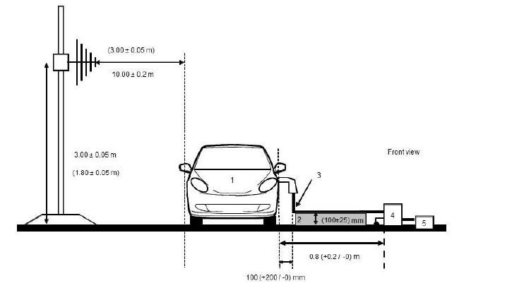
|
a0c0 |
| A4 | Figure 3b | a0c0 |
| A4 |
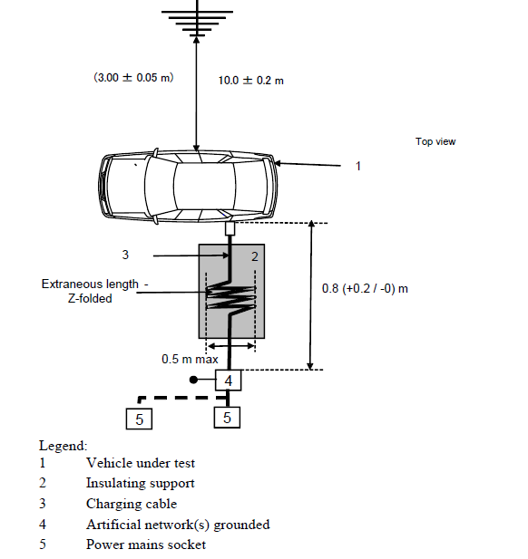
|
a0c0 |
| A4 | Vehicle in configuration "REESS charging mode" coupled to the power grid | a0c0 |
| A4 | Example of test setup for vehicle with plug located front/rear of vehicle (AC powered without communication) | a0c0 |
| A4 | Figure 3c | a0c0 |
| A4 |

|
a0c0 |
| A4 | Figure 3d | a0c0 |
| A4 |
|
a0c0 |
| A4 | Vehicle in configuration "REESS charging mode" coupled to the power grid | a0c0 |
| A4 | Example of test set-up for vehicle with plug located on vehicle side (AC or DC powered with communication) | a0c0 |
| A4 | Figure 3e | a0c0 |
| A4 |

|
a0c0 |
| A4 | Figure 3f | a0c0 |
| A4 |

|
a0c0 |
| A4 | Vehicle in configuration "REESS charging mode" coupled to the power grid | a0c0 |
| A4 | Example of test setup for vehicle with plug located front/rear of the vehicle (AC or DC powered with communication) | a0c0 |
| A4 | Figure 3g | a0c0 |
| A4 |
|
a0c0 |
| A4 | Figure 3h | a0c0 |
| A4 |

|
a0c0 |
| A5 |
|
a0c0 |
| A5 |
|
a0c0 |
| A5 1. | General | a0c0 |
| A5 1.1. | The test method described in this annex shall only be applied to vehicles. This method concerns only the configuration of the vehicle other than "REESS charging mode coupled to the power grid". | a0c0 |
| A5 1.2. | Test method | a0c0 |
| A5 | This test is intended to measure the narrowband electromagnetic emissions that may emanate from microprocessor-based systems or other narrowband source. | a0c0 |
| A5 | If not otherwise stated in this annex the test shall be performed according to CISPR 12 or CISPR 25. | a0c0 |
| A5 1.3. |
As an initial step the levels of emissions in the Frequency Modulation (FM) band (76 to 108 MHz) shall be measured at the vehicle broadcast radio antenna with an average detector. If the level specified in paragraph 6.3.2.4. of this Regulation is not exceeded, then the vehicle shall be deemed to comply with the requirements of this annex in respect of that frequency band and the full test shall not be carried out. |
a0c0 |
| A5 1.4. |
As an alternative for vehicles of category L the measurement location can be chosen according to Annex 4, paragraphs 3.1. and 3.2. |
a0c0 |
| A5 2. | Vehicle state during tests | a0c0 |
| A5 2.1. | The ignition switch shall be switched on. The engine shall not be operating. | a0c0 |
| A5 2.2. | The vehicle's electronic systems shall all be in normal operating mode with the vehicle stationary. | a0c0 |
| A5 2.3. |
All equipment which can be switched on permanently by the driver or passenger with internal oscillators > 9 kHz or repetitive signals should be in normal operation. |
a0c0 |
| A5 3. | Test requirements | a0c0 |
| A5 3.1. |
The limits apply throughout the frequency range 30 to 1,000 MHz for measurements performed in a semi anechoic chamber or an outdoor test site. |
a0c0 |
| A5 3.2. | Measurements shall be performed with an average detector. | a0c0 |
| A5 3.3. | The measurements shall be performed with a spectrum analyser or a scanning receiver. The parameters to be used are defined in Table 1 and Table 2. | a0c0 |
| A5 | Table 1 | a0c0 |
| A5 | Spectrum analyser parameters | a0c0 |
| A5 |

|
a0c0 |
| A5 | Note: If a spectrum analyser is used for peak measurements, the video bandwidth shall be at least three times the resolution bandwidth (RBW). | a0c0 |
| A5 | Table 2 | a0c0 |
| A5 | Scanning receiver parameters | a0c0 |
| A5 |

|
a0c0 |
| A5 | a For purely broadband disturbances, the maximum frequency step size may be increased up to a value not greater than the bandwidth value. | a0c0 |
| A5 3.4. | Measurements | a0c0 |
| A5 | The Technical Service shall perform the test at the intervals specified in the CISPR 12 standard throughout the frequency range 30 to 1,000 MHz. | a0c0 |
| A5 |
Alternatively, if the manufacturer provides measurement data for the whole frequency band from a test laboratory accredited to the applicable parts of ISO 17025 and recognized by the Type Approval Authority, the Technical Service may divide the frequency range in 14 frequency bands 30–34, 34–45, 45–60, 60–80, 80–100, 100–130, 130–170, 170–225, 225–300, 300–400, 400–525, 525–700, 700–850 and 850–1,000 MHz and perform tests at the |
a0c0 |
| A5 | In the event that the limit is exceeded during the test, investigations shall be made to ensure that this is due to the vehicle and not to background radiation including broadband radiation from any ESA. | a0c0 |
| A5 3.5. | Readings | a0c0 |
| A5 |
The maximum of the readings relative to the limit (horizontal and vertical polarization and antenna location on the left and right-hand sides of the vehicle) in each of the 14 frequency bands shall be taken as the characteristic reading at the frequency at which the measurements were made. |
a0c0 |
| A6 |
|
a0c0 |
| A6 |
|
a0c0 |
| A6 1. | General | a0c0 |
| A6 1.1. | The test method described in this annex shall only be applied to vehicles. This method concerns both configurations of vehicle: | a0c0 |
| A6 | (a) Other than "REESS charging mode coupled to the power grid". | a0c0 |
| A6 | (b) "REESS charging mode coupled to the power grid". | a0c0 |
| A6 1.2. | Test method | a0c0 |
| A6 | This test is intended to demonstrate the immunity of the vehicle electronic systems. The vehicle shall be subject to electromagnetic fields as described in this annex. The vehicle shall be monitored during the tests. | a0c0 |
| A6 | If not otherwise stated in this annex the test shall be performed according to ISO 11451-2. | a0c0 |
| A6 1.3. | Alternative test methods | a0c0 |
| A6 | The test may be alternatively performed in an outdoor test site for all vehicles. The test facility shall comply with (national) legal requirements regarding the emission of electromagnetic fields. | a0c0 |
| A6 | If a vehicle is longer than 12 m and/or wider than 2.60 m and/or higher than 4.00 m, BCI (bulk current injection) method according to ISO 11451-4 shall be used in the frequency range 20 to 2,000 MHz with levels defined in paragraph 6.8.2.1. of this Regulation. | a0c0 |
| A6 2. | Vehicle state during tests | a0c0 |
| A6 2.1. | Vehicle in configuration other than "REESS charging mode coupled to the power grid. | a0c0 |
| A6 2.1.1. | The vehicle shall be in an unladen condition except for necessary test equipment. | a0c0 |
| A6 2.1.1.1. |
The engine shall normally turn the driving wheels at a steady speed of 50 km/h if there is no technical reason due to the vehicle to define a different condition. For vehicles of categories L1 and L2 the steady speed shall normally be turned at 25 km/h. The vehicle shall be on an appropriately loaded dynamometer or alternatively supported on insulated axle stands with minimum ground clearance if no dynamometer is available. Where appropriate, transmission shafts, belts or chains may be disconnected (e.g. trucks, two- and three-wheel vehicles). |
a0c0 |
| A6 2.1.1.2. | Basic vehicle conditions | a0c0 |
| A6 | The paragraph defines minimum test conditions (as far as applicable) and failures criteria for vehicle immunity tests. Other vehicle systems, which can affect immunity related functions, shall be tested in a way to be agreed between manufacturer and Technical Service. | a0c0 |
| A6 |

|
a0c0 |
| A6 |

|
a0c0 |
| A6 2.1.1.3. | All equipment which can be switched on permanently by the driver or passenger should be in normal operation. | a0c0 |
| A6 2.1.1.4. | All other systems which affect the driver's control of the vehicle shall be (on) as in normal operation of the vehicle. | a0c0 |
| A6 2.1.2. |
If there are vehicle electrical/electronic systems which form an integral part of the direct control of the vehicle, which will not operate under the conditions described in paragraph 2.1., it will be permissible for the manufacturer to provide a report or additional evidence to the Technical Service that the vehicle electrical/electronic system meets the requirements of this Regulation. Such evidence shall be retained in the type approval documentation. |
a0c0 |
| A6 2.1.3. | Only non-perturbing equipment shall be used while monitoring the vehicle. The vehicle exterior and the passenger compartment shall be monitored to determine whether the requirements of this annex are met (e.g. by using (a) video camera(s), a microphone, etc.). | a0c0 |
| A6 2.2. | Vehicle in configuration "REESS charging mode coupled to the power grid". | a0c0 |
| A6 2.2.1. | The vehicle shall be in an unladen condition except for necessary test equipment. | a0c0 |
| A6 2.2.1.1. | The vehicle shall be immobilized, engine OFF and in charging mode. | a0c0 |
| A6 2.2.1.2. | Basic vehicle conditions | a0c0 |
| A6 | The paragraph defines minimum test conditions (as far as applicable) and failures criteria for vehicle immunity tests. Other vehicle systems, which can affect immunity related functions, shall be tested in a way to be agreed between manufacturer and Technical Service. | a0c0 |
| A6 |

|
a0c0 |
| A6 2.2.1.3. | All other equipment which can be switched on permanently by the driver or passenger should be OFF. | a0c0 |
| A6 2.2.2. | Only non-perturbing equipment shall be used while monitoring the vehicle. The vehicle exterior and the passenger compartment shall be monitored to determine whether the requirements of this annex are met (e.g. by using (a) video camera(s), a microphone, etc.). | a0c0 |
| A6 2.2.3. | The test set-up for the connection of the vehicle in configuration "REESS charging mode coupled to the power grid" is shown in Figures 4a to 4h (depending of AC or DC power charging mode, location of charging plug and charging with or without communication) of Appendix 1 to this annex. | a0c0 |
| A6 2.3. | Charging station / Power mains | a0c0 |
| A6 | The charging station may be placed either in the test location or outside the test location. | a0c0 |
| A6 | Note 1: If the communication between the vehicle and the charging station could be simulated, the charging station may be replaced by the supply from power mains. | a0c0 |
| A6 | In both case duplicated power mains and communication lines socket(s) shall be placed in the test location with the following conditions: | a0c0 |
| A6 | (a) It shall be placed on the ground plane; | a0c0 |
| A6 | (b) The length of the harness between the power mains / communication lines socket and the AN(s) / IS(s) shall be kept as short as possible; | a0c0 |
| A6 | (c) The harness between the power mains / communication lines socket and the AN(s) / IS(s) shall be placed as close as possible of the ground plane. | a0c0 |
| A6 | Note 2: The power mains and communication lines socket(s) should be filtered. | a0c0 |
| A6 | If the charging station is placed inside the test location then harness between charging station and the power mains / communication lines socket shall be placed with the following conditions: | a0c0 |
| A6 | (a) The harness at charging station side shall hang vertically down to the ground plane; | a0c0 |
| A6 | (b) The extraneous length shall be placed as close as possible of the ground plane and "Z-folded" if necessary. | a0c0 |
| A6 | Note 3: The charging station should be placed outside the beam width of the emitting antenna. | a0c0 |
| A6 2.4. | Artificial networks | a0c0 |
| A6 | The AN(s) shall be mounted directly on the ground plane. The cases of the AN(s) shall be bonded to the ground plane. | a0c0 |
| A6 |
The measuring port of each AN shall be terminated with a 50 Ω load. |
a0c0 |
| A6 | The AN shall be placed as defined in Figures 4a to 4h. | a0c0 |
| A6 2.5. | Impedance stabilization | a0c0 |
| A6 | Communication lines shall be applied to the vehicle through IS(s). | a0c0 |
| A6 | The impedance stabilization (IS) to be connected in the network and communication cables is defined in CISPR 22 paragraph 9.6.2. | a0c0 |
| A6 | The IS(s) shall be mounted directly on the ground plane. The case of the IS(s) shall be bonded to the ground plane. | a0c0 |
| A6 |
The measuring port of each IS shall be terminated with a 50 Ω load. |
a0c0 |
| A6 | The IS shall be placed as defined in Figures 4e to 4h. | a0c0 |
| A6 2.6. | Power charging / Communication cable | a0c0 |
| A6 | The power charging / communication cable shall be placed in a straight line between the AN(s) / IS(s) and the vehicle charging plug. The projected cable length shall be 0.8 m (+0.2/-0 m). | a0c0 |
| A6 | If the length of the cable is longer than 1 m, the extraneous length shall be "Z-folded" in less than 0.5 m width. | a0c0 |
| A6 | The charging / communication cable at vehicle side shall hang vertically at a distance of 100 mm (+200/-0 mm) from the vehicle body. | a0c0 |
| A6 |
The whole cable shall be placed on a non-conductive, low relative permittivity (dielectric-constant) material (εr ≤ 1.4), at 100 mm (±25 mm) above the ground plane. |
a0c0 |
| A6 3. | Reference point | a0c0 |
| A6 3.1. | For the purposes of this annex, the reference point is the point at which the field strength shall be established and shall be defined as follows: | a0c0 |
| A6 3.2. | For categories M, N, O vehicles according to ISO 11451-2. | a0c0 |
| A6 3.3. | For category L vehicles: | a0c0 |
| A6 3.3.1. |
At least 2 m horizontally from the antenna phase centre or at least 1 m vertically from the radiating elements of a transmission-line-system (TLS); |
a0c0 |
| A6 3.3.2. | On the vehicle's centre line (plane of longitudinal symmetry); | a0c0 |
| A6 3.3.3. |
At a height of 1.0 ± 0.05 m above the plane on which the vehicle rests or 2.0 ± 0.05 m if the minimum height of the roof of any vehicle in the model range exceeds 3.0 m, |
a0c0 |
| A6 3.3.4. |
Either at 1.0 ± 0.2 m behind the vertical centreline of the vehicle's front wheel (point C in Figure 1 of Appendix 1 to this annex) in the case of three-wheeled vehicles, |
a0c0 |
| A6 |
Or at 0.2 ± 0.2 m behind the vertical centreline of the vehicle's front wheel (point D in Figure 2 of Appendix 1 to this annex) in the case of two-wheeled vehicles. |
a0c0 |
| A6 3.3.5. |
If it is decided to radiate the rear of the vehicle, the reference point shall be established as in paragraphs 3.3.1. to 3.3.4. above. The vehicle shall then be installed facing away from the antenna and positioned as if it had been horizontally rotated 180 around its centre point, i.e. such that the distance from the antenna to the nearest part of the outer body of the vehicle remains the same. This is illustrated in Figure 3 of Appendix 1 to this annex. |
a0c0 |
| A6 4. | Test requirements | a0c0 |
| A6 4.1. | Frequency range, dwell times, polarization | a0c0 |
| A6 |
The vehicle shall be exposed to electromagnetic radiation in the 20 to 2,000 MHz frequency ranges in vertical polarization. |
a0c0 |
| A6 | The test signal modulation shall be: | a0c0 |
| A6 | (a) AM (amplitude modulation), with 1 kHz modulation and 80 per cent modulation depth in the 20 to 800 MHz frequency range, and | a0c0 |
| A6 |
(b) PM (pulse modulation), Ton 577 µs, period 4,600 µs in the 800 to 2,000 MHz frequency range, |
a0c0 |
| A6 | If not otherwise agreed between Technical Service and vehicle manufacturer. | a0c0 |
| A6 |
Frequency step size and dwell time shall be chosen according to ISO 11451-1. |
a0c0 |
| A6 4.1.1. |
The Technical Service shall perform the test at the intervals specified in ISO 11451-1 throughout the frequency range 20 to 2,000 MHz. |
a0c0 |
| A6 | Alternatively, if the manufacturer provides measurement to data for the whole frequency band from a test laboratory accredited to the applicable parts of ISO 17025 and recognized by the Type Approval Authority, the Technical Service may choose a reduced number of spot frequencies in the range, e.g. 27, 45, 65, 90, 120, 150, 190, 230, 280, 380, 450, 600, 750, 900, 1,300 and 1,800 MHz to confirm that the vehicle meets the requirements of this annex. | a0c0 |
| A6 | If a vehicle fails the test defined in this annex, it shall be verified as having failed under the relevant test conditions and not as a result of the generation of uncontrolled fields. | a0c0 |
| A6 5. | Generation of required field strength | a0c0 |
| A6 5.1. | Test methodology | a0c0 |
| A6 5.1.1. | The substitution method according to ISO 11451-1, shall be used to establish the test field conditions. | a0c0 |
| A6 5.1.2. | Calibration | a0c0 |
| A6 | For TLS one field probe at the facility reference point shall be used. | a0c0 |
| A6 | For antennas four field probes at the facility reference line shall be used. | a0c0 |
| A6 5.1.3. | Test phase | a0c0 |
| A6 |
The vehicle shall be positioned with the centre line of the vehicle on the facility reference point or line. The vehicle shall normally face a fixed antenna. However, where the electronic control units and the associated wiring harness are predominantly in the rear of the vehicle, the test should normally be carried out with the vehicle facing away from the antenna. In the case of long vehicles (i.e. excluding vehicles of categories L, M1 and N1), which have electronic control units and associated wiring harness predominantly towards the middle of the vehicle, a reference point may be established based on either the right side surface or the left side surface of the vehicle. This reference point shall be at the midpoint of the vehicle's length or at one point along the side of the vehicle chosen by the manufacturer in conjunction with the Type Approval Authority after considering the distribution of electronic systems and the layout of any wiring harness. |
a0c0 |
| A6 | Such testing may only take place if the physical construction of the chamber permits. The antenna location shall be noted in the test report. | a0c0 |
| A6 |
|
a0c0 |
| A6 | Figure 1 | a0c0 |
| A6 |
|
a0c0 |
| A6 | Figure 2 | a0c0 |
| A6 |
|
a0c0 |
| A6 | Figure 3 | a0c0 |
| A6 |
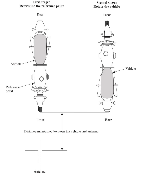
|
a0c0 |
| A6 | Figure 4 | a0c0 |
| A6 | Vehicle in configuration "REESS charging mode coupled to the power grid" | a0c0 |
| A6 | Example of test set-up for vehicle with plug located on the vehicle side (AC power charging without communication) | a0c0 |
| A6 | Figure 4a | a0c0 |
| A6 |

|
a0c0 |
| A6 | Figure 4b | a0c0 |
| A6 |
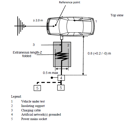
|
a0c0 |
| A6 | Example of test set-up for vehicle with plug located front / rear of vehicle (AC power charging without communication) | a0c0 |
| A6 | Figure 4c | a0c0 |
| A6 |
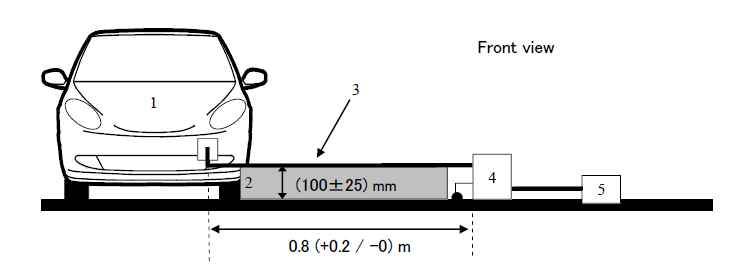
|
a0c0 |
| A6 | Figure 4d | a0c0 |
| A6 |

|
a0c0 |
| A6 | Example of test set-up for vehicle with plug located on vehicle side (AC or DC power charging with communication) | a0c0 |
| A6 | Figure 4e | a0c0 |
| A6 |
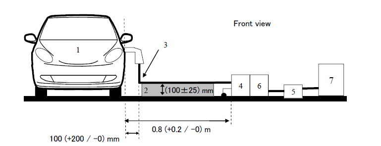
|
a0c0 |
| A6 | Figure 4f | a0c0 |
| A6 |

|
a0c0 |
| A6 | Example of test set-up for vehicle with plug located front / rear of the vehicle (AC or DC power charging with communication) | a0c0 |
| A6 | Figure 4g | a0c0 |
| A6 |
|
a0c0 |
| A6 | Figure 4h | a0c0 |
| A6 |
|
a0c0 |
| A7 |
|
a0c0 |
| A7 |
|
a0c0 |
| A7 1. | General | a0c0 |
| A7 1.1. | The test method described in this annex may be applied to ESAs, which may be subsequently fitted to vehicles, which comply with Annex 4. | a0c0 |
| A7 | This method concerns both kinds of ESA: | a0c0 |
| A7 | (a) Other ESAs than involved in "REESS charging mode coupled to the power grid". | a0c0 |
| A7 | (b) ESAs involved in "REESS charging mode coupled to the power grid". | a0c0 |
| A7 1.2. | Test method | a0c0 |
| A7 | This test is intended to measure broadband electromagnetic emissions from ESAs (e.g. ignition systems, electric motor, onboard battery charging unit, etc.) | a0c0 |
| A7 | If not otherwise stated in this annex the test shall be performed according CISPR 25. | a0c0 |
| A7 2. | ESA state during tests | a0c0 |
| A7 2.1. | The ESA under test shall be in normal operation mode, preferably in maximum load. | a0c0 |
| A7 | ESAs involved in "REESS charging mode coupled to the power grid" shall be in charging mode. | a0c0 |
| A7 | The state of charge (SOC) of the traction battery shall be kept between 20 per cent and 80 per cent of the maximum SOC during the whole frequency range measurement (this may lead to split the measurement in different sub-bands with the need to discharge the vehicle's traction battery before starting the next sub-bands) | a0c0 |
| A7 | If the test is not performed with a REESS the ESA should be tested at rated current. If the current consumption can be adjusted, then the current shall be set to at least 80 per cent of its nominal value. | a0c0 |
| A7 3. | Test arrangements | a0c0 |
| A7 3.1. | For ESA other than involved in "REESS charging mode coupled to the power grid" the test shall be performed according to the ALSE method described in paragraph 6.4. of CISPR 25. | a0c0 |
| A7 3.2. | For ESAs in configuration "REESS charging mode coupled to the power grid" the test arrangement shall be according to Figure 2 of the appendix to this annex. | a0c0 |
| A7 3.2.1. | The shielding configuration shall be according to the vehicle series configuration. Generally all shielded High Voltage (HV) parts shall be properly connected with low impedance to ground (e. g. AN, cables, connectors etc.). ESAs and loads shall be connected to ground. The external HV power supply shall be connected via feed-through-filtering. | a0c0 |
| A7 3.2.2. |
Unless otherwise specified the length of the Low Voltage (LV) harness and the HV harness parallel to the front edge of the ground plane shall be 1,500 mm (±75 mm). The total length of the test harness including the connector shall be 1,700 mm (+300/-0 mm). The distance between the LV harness and the HV harness shall be 100 mm (+100/-0 mm). |
a0c0 |
| A7 3.2.3. |
All of the harnesses shall be placed on a non-conductive, low relative permittivity material (εr ≤ 1.4), at 50 mm (±5 mm) above the ground plane. |
a0c0 |
| A7 3.2.4. | Shielded supply lines for HV+ and HV- line and three phase lines may be coaxial cables or in a common shield depending on the used plug system. The original HV-harness from the vehicle may be used optionally. | a0c0 |
| A7 3.2.5. | Unless otherwise specified, the ESA case shall be connected to the ground plane either directly or via defined impedance. | a0c0 |
| A7 3.2.6. | For onboard chargers, the AC/DC power lines shall be placed the furthest from the antenna (behind LV and HV harness). The distance between the AC/DC power lines and the closest harness (LV or HV) shall be 100 mm (+100/-0 mm). | a0c0 |
| A7 3.3. | Alternative measuring location | a0c0 |
| A7 | As an alternative to an absorber lined shielded enclosure (ALSE) an open area test site (OATS), which complies with the requirements of CISPR 16-1-4 may be used (see appendix to this annex). | a0c0 |
| A7 3.4. | Ambient | a0c0 |
| A7 | To ensure that there is no extraneous noise or signal of a magnitude sufficient to affect materially the measurement, measurements shall be taken before or after the main test. In this measurement, the extraneous noise or signal shall be at least 6 dB below the limits of interference given in paragraph 6.5.2.1. of this Regulation, except for intentional narrowband ambient transmissions. | a0c0 |
| A7 4. | Test requirements | a0c0 |
| A7 4.1. | The limits apply throughout the frequency range 30 to 1,000 MHz for measurements performed in a semi anechoic chamber or an outdoor test site. | a0c0 |
| A7 4.2. | Measurements can be performed with either quasi-peak or peak detectors. The limits given in paragraphs 6.2. and 6.5. of this Regulation are for quasi-peak detectors. If peak detectors are used a correction factor of 20 dB as defined in CISPR 12 shall be applied. | a0c0 |
| A7 4.3. | The measurements shall be performed with a spectrum analyser or a scanning receiver. The parameters to be used are defined in Table 1 and Table 2. | a0c0 |
| A7 | Table 1 | a0c0 |
| A7 | Spectrum analyser parameters | a0c0 |
| A7 |
|
a0c0 |
| A7 | Note: If a spectrum analyser is used for peak measurements, the video bandwidth shall be at least three times the resolution bandwidth (RBW). | a0c0 |
| A7 | Table 2 | a0c0 |
| A7 | Scanning receiver parameters | a0c0 |
| A7 |

|
a0c0 |
| A7 | a For purely broadband disturbances, the maximum frequency step size may be increased up to a value not greater than the bandwidth value. | a0c0 |
| A7 | Note: For emissions generated by brush commutator motors without an electronic control unit, the maximum step size may be increased up to five times the bandwidth. | a0c0 |
| A7 4.4. | Measurements | a0c0 |
| A7 | Unless otherwise specified the configuration with the LV harness closer to the antenna shall be tested. | a0c0 |
| A7 |
The phase centre of the antenna shall be in line with the centre of the longitudinal part of the wiring harnesses for frequencies up to 1,000 MHz. |
a0c0 |
| A7 |
The Technical Service shall perform the test at the intervals specified in the CISPR 12 standard throughout the frequency range 30 to 1,000 MHz. |
a0c0 |
| A7 |
Alternatively, if the manufacturer provides measurement to data for the whole frequency band from a test laboratory accredited to the applicable parts of ISO 17025 and recognized by the Type Approval Authority, the Technical Service may divide the frequency range in 14 frequency bands 30– 34, 34–45, 45–60, 60–80, 80–100, 100–130, 130–170, 170–225, 225–300, 300–400, 400–525, 525–700, 700–850 and 850– 1,000 MHz and perform tests at the 14 frequencies giving the highest emission levels within each band to confirm that the ESA meets the requirements of this annex. |
a0c0 |
| A7 | In the event that the limit is exceeded during the test, investigations shall be made to ensure that this is due to the ESA and not to background radiation. | a0c0 |
| A7 4.5. | Readings | a0c0 |
| A7 | The maximum of the readings relative to the limit (horizontal/vertical polarization) in each of the 14 frequency bands shall be taken as the characteristic reading at the frequency at which the measurements were made. | a0c0 |
| A7 |
|
a0c0 |
| A7 | Figure 1 | a0c0 |
| A7 | Open area test site: Electrical/electronic sub-assembly test area boundary | a0c0 |
| A7 | Level clear area free from electromagnetic reflecting surfaces | a0c0 |
| A7 |
|
a0c0 |
| A7 | Figure 2 | a0c0 |
| A7 | Test configuration for ESAs involved in "REESS charging mode coupled to the power grid" (example for biconical antenna) | a0c0 |
| A7 |

|
a0c0 |
| A8 |
|
a0c0 |
| A8 |
|
a0c0 |
| A8 1. | General | a0c0 |
| A8 1.1. | The test method described in this annex may be applied to ESAs, which may be subsequently fitted to vehicles, which comply, with Annex 5. | a0c0 |
| A8 | This method concerns only ESA other than those involved in "REESS charging mode coupled to the power grid". | a0c0 |
| A8 1.2. | Test method | a0c0 |
| A8 | This test is intended to measure the narrowband electromagnetic emissions such as might emanate from a microprocessor-based system. | a0c0 |
| A8 | If not otherwise stated in this annex the test shall be performed according to CISPR 25. | a0c0 |
| A8 2. | ESA state during tests | a0c0 |
| A8 | The ESA under test shall be in normal operation mode, preferably in maximum load. | a0c0 |
| A8 3. | Test arrangements | a0c0 |
| A8 3.1. | The test shall be performed according to ALSE method described in paragraph 6.4. of CISPR 25. | a0c0 |
| A8 3.2. | Alternative measuring location | a0c0 |
| A8 | As an alternative to an absorber lined shielded enclosure (ALSE) an open area test site (OATS) which complies with the requirements of CISPR 16-1-4 may be used (see Figure 1 of the appendix to Annex 7). | a0c0 |
| A8 3.3. | Ambient | a0c0 |
| A8 | To ensure that there is no extraneous noise or signal of a magnitude sufficient to affect materially the measurement; measurements shall be taken before or after the main test. In this measurement, the extraneous noise or signal shall be at least 6 dB below the limits of interference given in paragraph 6.6.2.1. of this Regulation, except for intentional narrowband ambient transmissions. | a0c0 |
| A8 4. | Test requirements | a0c0 |
| A8 4.1. | The limits apply throughout the frequency range 30 to 1,000 MHz for measurements performed in semi anechoic chambers or outdoor test sites. | a0c0 |
| A8 4.2. | Measurements shall be performed with an average detector. | a0c0 |
| A8 4.3. | The measurements shall be performed with a spectrum analyser or a scanning receiver. The parameters to be used are defined in Tables 1 and 2. | a0c0 |
| A8 | Table 1 | a0c0 |
| A8 | Spectrum analyser parameters | a0c0 |
| A8 |

|
a0c0 |
| A8 | Note: If a spectrum analyser is used for peak measurements, the video band width shall be at least three times the resolution band width (RBW) | a0c0 |
| A8 | Table 2 | a0c0 |
| A8 | Scanning receiver parameters | a0c0 |
| A8 |
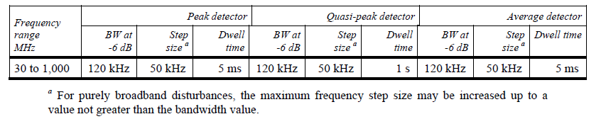
|
a0c0 |
| A8 | a For purely broadband disturbances, the maximum frequency step size may be increased up to a value not greater than the bandwidth value. | a0c0 |
| A8 | Note: For emissions generated by brush commutator motors without an electronic control unit, the maximum step size may be increased up to five times the band width. | a0c0 |
| A8 4.4. | Measurements | a0c0 |
| A8 | The Technical Service shall perform the test at the intervals specified in the CISPR 12 standard throughout the frequency range 30 to 1,000 MHz. | a0c0 |
| A8 |
Alternatively, if the manufacturer provides measurement to data for the whole frequency band from a test laboratory accredited to the applicable parts of ISO 17025 and recognized by the Type Approval Authority, the Technical Service may divide the frequency range in 14 frequency bands 30– 34, 34–45, 45–60, 60–80, 80–100, 100–130, 130–170, 170–225, 225–300, 300–400, 400–525, 525–700, 700–850 and 850–1,000 MHz and perform tests at the 14 frequencies giving the highest emission levels within each band to confirm that the ESA meets the requirements of this annex. In the event that the limit is exceeded during the test, investigations shall be made to ensure that this is due to the ESA and not to background radiation including broadband radiation from the ESA. |
a0c0 |
| A8 4.5. | Readings | a0c0 |
| A8 | The maximum of the readings relative to the limit (horizontal/vertical polarisation) in each of the 14 frequency bands shall be taken as the characteristic reading at the frequency at which the measurements were made. | a0c0 |
| A9 |
|
a0c0 |
| A9 |
|
a0c0 |
| A9 1. | General | a0c0 |
| A9 1.1. | The test method(s) described in this annex applies to ESAs. | a0c0 |
| A9 1.2. | Test methods | a0c0 |
| A9 | This method concerns both kinds of ESA: | a0c0 |
| A9 | (a) Other ESAs than involved in "REESS charging mode coupled to the power grid"; | a0c0 |
| A9 | (b) ESAs involved in "REESS charging mode coupled to the power grid". | a0c0 |
| A9 1.2.1. | ESAs may comply with the requirements of any combination of the following test methods at the manufacturer's discretion provided that these results in the full frequency range specified in paragraph 3.1. of this annex being covered: | a0c0 |
| A9 | (a) Absorber chamber test according to ISO 11452-2; | a0c0 |
| A9 | (b) TEM cell testing according to ISO 11452-3; | a0c0 |
| A9 | (c) Bulk current injection testing according to ISO 11452-4; | a0c0 |
| A9 | (d) Stripline testing according to ISO 11452-5; | a0c0 |
| A9 | (e) 800 mm stripline according to paragraph 4.5. of this annex. | a0c0 |
| A9 | ESAs in configuration "REESS charging mode coupled to the power grid" shall comply with the requirements of the combination of the Absorber chamber test according to ISO 11452-2 and Bulk current injection testing according to ISO 11452-4 at the manufacturer's discretion provided that these results in the full frequency range specified in paragraph 3.1. of this annex being covered. | a0c0 |
| A9 | (Frequency range and general test conditions shall be based on ISO 11452-1). | a0c0 |
| A9 2. | State of ESA during tests | a0c0 |
| A9 2.1. | The test conditions shall be according ISO 11452-1. | a0c0 |
| A9 2.2. | The ESA under test shall be switched on and shall be stimulated to be in normal operation condition. It shall be arranged as defined in this annex unless individual test methods dictate otherwise. | a0c0 |
| A9 | ESAs involved in "REESS charging mode coupled to the power grid" shall be in charging mode. | a0c0 |
| A9 | The state of charge (SOC) of the traction battery shall be kept between 20 per cent and 80 per cent of the maximum SOC during the whole frequency range measurement (this may lead to split the measurement in different sub-bands with the need to discharge the vehicle's traction battery before starting the next sub-bands). | a0c0 |
| A9 | If the test is not performed with a REESS the ESA should be tested at rated current. If the current consumption can be adjusted, then the current shall be set to at least 20 per cent of its nominal value. | a0c0 |
| A9 2.3. | Any extraneous equipment required to operate the ESA under test shall not be in place during the calibration phase. No extraneous equipment shall be closer than 1 m from the reference point during calibration. | a0c0 |
| A9 2.4. | To ensure reproducible measurement results are obtained when tests and measurements are repeated, the test signal generating equipment and its layout shall be to the same specification as that used during each appropriate calibration phase. | a0c0 |
| A9 2.5. | If the ESA under test consists of more than one unit, the interconnecting cables should ideally be the wiring harnesses as intended for use in the vehicle. If these are not available, the length between the electronic control unit and the AN shall be as defined in the standard. All cables in the wiring harness should be terminated as realistically as possible and preferably with real loads and actuators. | a0c0 |
| A9 3. | General test requirements | a0c0 |
| A9 3.1. | Frequency range, dwell times | a0c0 |
| A9 | Measurements shall be made in the 20 to 2,000 MHz frequency range with frequency steps according to ISO 11452-1. | a0c0 |
| A9 | The test signal modulation shall be: | a0c0 |
| A9 | (a) AM (amplitude modulation), with 1 kHz modulation and 80 per cent modulation depth in the 20 to 800 MHz frequency range, and | a0c0 |
| A9 |
(b) PM (pulse modulation), Ton 577 µs, period 4,600 µs in the 800 to 2,000 MHz frequency range, |
a0c0 |
| A9 | If not otherwise agreed between Technical Service and ESA manufacturer. | a0c0 |
| A9 | Frequency step size and dwell time shall be chosen according to ISO 11452-1. | a0c0 |
| A9 3.2. | The Technical Service shall perform the test at the intervals specified in | a0c0 |
| A9 | ISO 11452-1, throughout the frequency range 20 to 2,000 MHz. | a0c0 |
| A9 | Alternatively, if the manufacturer provides measurement to data for the whole frequency band from a test laboratory accredited to the applicable parts of ISO 17025, and recognized by the Type Approval Authority, the Technical Service may choose a reduced number of spot frequencies in the range, e.g. 27, 45, 65, 90, 120, 150, 190, 230, 280, 380, 450, 600, 750, 900, 1,300, and 1,800 MHz to confirm that the ESA meets the requirements of this annex. | a0c0 |
| A9 3.3. | If an ESA fails the tests defined in this annex, it shall be verified as having failed under the relevant test conditions and not as a result of the generation of uncontrolled fields. | a0c0 |
| A9 4. | Specific test requirements | a0c0 |
| A9 4.1. | Absorber chamber test | a0c0 |
| A9 4.1.1. | Test method | a0c0 |
| A9 | This test method allows the testing of vehicle electrical/electronic systems by exposing an ESA to electromagnetic radiation generated by an antenna. | a0c0 |
| A9 4.1.2. | Test methodology | a0c0 |
| A9 | The "substitution method" shall be used to establish the test field conditions according ISO 11452-2. | a0c0 |
| A9 | The test shall be performed with vertical polarization. | a0c0 |
| A9 4.1.2.1. | For ESAs in configuration "REESS charging mode coupled to the power grid" the test arrangement shall be according to Appendix 3 to this annex. | a0c0 |
| A9 4.1.2.1.1. | The shielding configuration shall be according to the vehicle series configuration. Generally all shielded HV parts shall be properly connected with low impedance to ground (e. g. AN, cables, connectors etc.). ESAs and loads shall be connected to ground. The external HV power supply shall be connected via feed-through-filtering. | a0c0 |
| A9 4.1.2.1.2. |
Unless otherwise specified the length of the LV harness and the HV harness parallel to the front edge of the ground plane shall be 1,500 mm (±75 mm). The total length of the test harness including the connector shall be 1,700 mm (+300/-0 mm). The distance between the LV harness and the HV harness shall be 100 mm (+100/-0 mm). |
a0c0 |
| A9 4.1.2.1.3. |
All of the harnesses shall be placed on a non-conductive, low relative permittivity material (εr ≤ 1,4), at 50 mm (±5 mm) above the ground plane. |
a0c0 |
| A9 4.1.2.1.4. | Shielded supply lines for HV+ and HV- line and three phase lines may be coaxial cables or in a common shield depending on the used plug system. The original HV-harness from the vehicle may be used optionally. | a0c0 |
| A9 4.1.2.1.5. | Unless otherwise specified, the ESA case shall be connected to the ground plane either directly or via defined impedance. | a0c0 |
| A9 4.1.2.1.6. | For onboard chargers, the AC/DC power lines shall be placed the furthest from the antenna (behind LV and HV harness). The distance between the AC/DC power lines and the closest harness (LV or HV) shall be 100 mm (+100/-0 mm). | a0c0 |
| A9 4.1.2.1.7. | Unless otherwise specified, the configuration with the LV harness closer to the antenna shall be tested. | a0c0 |
| A9 4.2. | TEM cell testing (see Appendix 2 to this annex) | a0c0 |
| A9 4.2.1. | Test method | a0c0 |
| A9 | The TEM (transverse electromagnetic mode) cell generates homogeneous fields between the internal conductor (septum) and housing (ground plane). | a0c0 |
| A9 4.2.2. | Test methodology | a0c0 |
| A9 | The test shall be performed according ISO 11452-3. | a0c0 |
| A9 | Depending on the ESA to be tested the Technical Service shall chose the method of maximum field coupling to the ESA or to the wiring harness inside the TEM-cell. | a0c0 |
| A9 4.3. | Bulk current injection testing | a0c0 |
| A9 4.3.1. | Test method | a0c0 |
| A9 | This is a method of carrying out immunity tests by inducing currents directly into a wiring harness using a current injection probe. | a0c0 |
| A9 4.3.2. | Test methodology | a0c0 |
| A9 | The test shall be performed according to ISO 11452-4 on a test bench. As an alternative the ESA may be tested while installed in the vehicle according to ISO 11451-4 with the following characteristics: | a0c0 |
| A9 | (a) The injection probe shall be positioned in 150 mm distance to the ESA to be tested; | a0c0 |
| A9 | (b) The reference method shall be used to calculate injected currents from forward power; | a0c0 |
| A9 | (c) The frequency range of the method is limited by the injection probe specification. | a0c0 |
| A9 4.3.2.1. | For ESAs in configuration "REESS charging mode coupled to the power grid", the test arrangement shall be according to Appendix 4 to this annex. | a0c0 |
| A9 4.3.2.1.1. | The shielding configuration shall be according to the vehicle series configuration. Generally all shielded HV parts shall be properly connected with low impedance to ground (e. g. AN, cables, connectors, etc.). ESAs and loads shall be connected to ground. The external HV power supply shall be connected via feed-through-filtering. | a0c0 |
| A9 4.3.2.1.2. | Unless otherwise specified the length of the LV harness and the HV harness shall be 1,700 mm (+300/-0 mm). The distance between the LV harness and the HV harness shall be 100 mm (+100/-0 mm). | a0c0 |
| A9 4.3.2.1.3. |
All of the harnesses shall be placed on a non-conductive, low relative permittivity material (εr≤1.4), at (50 ± 5) mm above the ground plane. |
a0c0 |
| A9 4.3.2.1.4. | Shielded supply lines for HV+ and HV- line and three phase lines may be coaxial cables or in a common shield depending on the used plug system. The original HV-harness from the vehicle may be used optionally. | a0c0 |
| A9 4.3.2.1.5. | Unless otherwise specified, the ESA case shall be connected to the ground plane either directly or via defined impedance. | a0c0 |
| A9 4.3.2.1.6. | Unless otherwise specified the test shall be performed with the injection probe placed around each of the following harnesses: | a0c0 |
| A9 | (a) Low voltage harness; | a0c0 |
| A9 | (b) High voltage harness; | a0c0 |
| A9 | (c) AC power lines if applicable; | a0c0 |
| A9 | (d) DC power lines if applicable. | a0c0 |
| A9 4.4. | Stripline testing | a0c0 |
| A9 4.4.1. | Test method | a0c0 |
| A9 | This test method consists of subjecting the wiring harness connecting the components in an ESA to specified field strengths. | a0c0 |
| A9 4.4.2. | Test methodology | a0c0 |
| A9 | The test shall be performed according to ISO 11452-5. | a0c0 |
| A9 4.5. | 800 mm stripling testing | a0c0 |
| A9 4.5.1. | Test method | a0c0 |
| A9 | The stripline consists of two parallel metallic plates separated by 800 mm. Equipment under test is positioned centrally between the plates and subjected to an electromagnetic field (see Appendix 1 to this annex). | a0c0 |
| A9 | This method can test complete electronic systems including sensors and actuators as well as the controller and wiring loom. It is suitable for apparatus whose largest dimension is less than one-third of the plate separation. | a0c0 |
| A9 4.5.2. | Test methodology | a0c0 |
| A9 4.5.2.1. | Positioning of stripline | a0c0 |
| A9 | The stripline shall be housed in a screened room (to prevent external emissions) and positioned 2 m away from walls and any metallic enclosure to prevent electromagnetic reflections. RF absorber material may be used to damp these reflections. The stripline shall be placed on non-conducting supports at least 0.4 m above the floor. | a0c0 |
| A9 4.5.2.2. | Calibration of the stripline | a0c0 |
| A9 | A field-measuring probe shall be positioned within the central one-third of the longitudinal, vertical and transverse dimensions of the space between the parallel plates with the system under test absent. | a0c0 |
| A9 | The associated measuring equipment shall be sited outside the screen room. At each desired test frequency, a level of power shall be fed into the stripline to produce the required field strength at the antenna. This level of forward power, or another parameter directly related to the forward power required to define the field, shall be used for type approval tests unless changes occur in the facilities or equipment, which necessitate this procedure being repeated. | a0c0 |
| A9 4.5.2.3. | Installation of the ESA under test | a0c0 |
| A9 | The main control unit shall be positioned within the central one third of the longitudinal, vertical and transverse dimensions of the space between the parallel plates. It shall be supported on a stand made from non-conducting material. | a0c0 |
| A9 4.5.2.4. | Main wiring loom and sensor/actuator cables | a0c0 |
| A9 | The main wiring loom and any sensor/actuator cables shall rise vertically from the control unit to the top ground plate (this helps to maximize coupling with the electromagnetic field). Then they shall follow the underside of the plate to one of its free edges where they shall loop over and follow the top of the ground plate as far as the connections to the stripline feed. The cables shall then be routed to the associated equipment, which shall be sited in an area outside the influence of the electromagnetic field, e.g. on the floor of the screened room 1 m longitudinally away from the stripline. | a0c0 |
| A9 |
|
a0c0 |
| A9 | Figure 1 | a0c0 |
| A9 |
800 mm Stripline testing |
a0c0 |
| A9 |

|
a0c0 |
| A9 | Figure 2 | a0c0 |
| A9 |
800 mm stripline dimensions |
a0c0 |
| A9 |
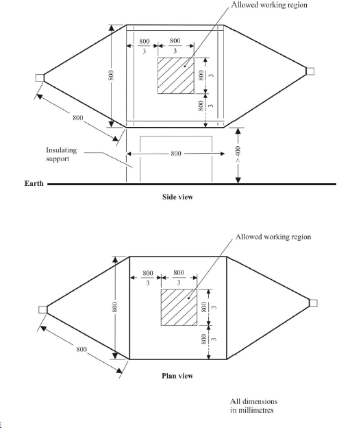
|
a0c0 |
| A9 |
|
a0c0 |
| A9 |
|
a0c0 |
| A9 | The following table shows the dimensions for constructing a cell with specified upper frequency limits: | a0c0 |
| A9 |

|
a0c0 |
| A9 |
|
a0c0 |
| A9 |
|
a0c0 |
| A9 | Test configuration for ESA's involved in "REESS charging mode coupled to the power grid". The test shall be performed according to ISO 11452-2. | a0c0 |
| A9 |

|
a0c0 |
| A9 |
|
a0c0 |
| A9 |
|
a0c0 |
| A9 | Test configuration for ESAs involved in "REESS charging mode coupled to the power grid". The test shall be performed according to ISO 11452-4. | a0c0 |
| A9 |

|
a0c0 |
| A10 |
|
a0c0 |
| A10 |
|
a0c0 |
| A10 1. | General | a0c0 |
| A10 | This test method shall ensure the immunity of ESAs to conducted transients on the vehicle power supply and limit conducted transients from ESAs to the vehicle power supply. | a0c0 |
| A10 2. | Immunity against transient disturbances conducted along 12/24 V supply lines. | a0c0 |
| A10 | Apply the test pulses 1, 2a, 2b, 3a, 3b and 4 according to the International Standard ISO 7637-2 to the supply lines as well as to other connections of ESAs which may be operationally connected to supply lines. | a0c0 |
| A10 3. | Emission of transient conducted disturbances generated by ESAs on 12/24 V supply lines | a0c0 |
| A10 | Measurement according to the International Standard ISO 7637-2 on supply lines as well as to other connections of ESAs which may be operationally connected to supply lines. | a0c0 |
| A11 |
|
a0c0 |
| A11 |
|
a0c0 |
| A11 1. | General | a0c0 |
| A11 1.1. | The test method described in this annex shall be applied to vehicles in configuration "REESS charging mode coupled to the power grid" | a0c0 |
| A11 1.2. | Test method | a0c0 |
| A11 | This test is intended to measure the level of harmonics generated by vehicle in configuration "REESS charging mode coupled to the power grid" through its AC power lines in order to ensure it is compatible with residential, commercial and light industrial environments. | a0c0 |
| A11 | If not otherwise stated in this annex the test shall be performed according to: | a0c0 |
| A11 | (a) IEC 61000-3-2 for input current in charging mode ≤ 16 A per phase for class A equipment; | a0c0 |
| A11 |
(b) IEC 61000-3-12 for input current in charging mode > 16 A and ≤ 75 A per phase. |
a0c0 |
| A11 2. | Vehicle state during tests | a0c0 |
| A11 2.1. | The vehicle shall be in configuration "REESS charging mode coupled to the power grid". | a0c0 |
| A11 |
The state of charge (SOC) of the traction battery shall be kept between 20 per cent and 80 per cent of the maximum SOC during the whole time duration of the measurement (this may lead to the measurement being split into different time slots with the need to discharge the vehicle's traction battery before starting the next time slot). If the current consumption can be adjusted, then the current shall be set to at least 80 per cent of its nominal value. |
a0c0 |
| A11 | The vehicle shall be immobilized, engine OFF. | a0c0 |
| A11 | And all other equipment which can be switched on permanently by the driver or passenger should be OFF. | a0c0 |
| A11 3. | Test arrangements | a0c0 |
| A11 3.1. | The observation time to be used for the measurements shall be as for quasi-stationary equipment as defined in IEC 61000-3-2, Table 4. | a0c0 |
| A11 3.2. | The test set-up for single phase vehicle in configuration "REESS charging mode coupled to the power grid" is shown in Figure 1 of Appendix 1 to this annex. | a0c0 |
| A11 3.3. | The test set-up for three-phase vehicle in configuration "REESS charging mode coupled to the power grid" is shown in Figure 2 of Appendix 1 to this annex. | a0c0 |
| A11 4. | Test requirements | a0c0 |
| A11 4.1. | The measurements of even and odd current harmonics shall be performed up to the 40th harmonic. | a0c0 |
| A11 4.2. |
The limits for single phase or three-phase "REESS charging mode coupled to the power grid" with input current ≤ 16 A per phase are given in Table 3 of paragraph 7.3.2.1. of this Regulation. |
a0c0 |
| A11 4.3. |
The limits for single phase "REESS charging mode coupled to the power grid" with input current > 16 A and ≤ 75 A per phase are given in Table 4 of paragraph 7.3.2.2. of this Regulation. |
a0c0 |
| A11 4.4. |
The limits for three-phase "REESS charging mode coupled to the power grid" with input current > 16 A and ≤ 75 A per phase are given in Table 5 of paragraph 7.3.2.2. of this Regulation. |
a0c0 |
| A11 4.5. | For three-phase "REESS charging mode coupled to the power grid" with input current > 16 A and ≤ 75 A per phase, when at least one of the three conditions a), b) or c) described in paragraph 5.2. of IEC 61000-3-12 is fulfilled, then the limits given in Table 6 of paragraph 7.3.2.2. of this Regulation can be applied. | a0c0 |
| A11 |
|
a0c0 |
| A11 | Figure 1 | a0c0 |
| A11 |
Vehicle in configuration "REESS charging mode coupled to the power grid" - Single phase charger test set-up |
a0c0 |
| A11 |

|
a0c0 |
| A11 | Figure 2 | a0c0 |
| A11 |
Vehicle in configuration "REESS charging mode coupled to the power grid" - Three-phase charger test set-up |
a0c0 |
| A11 |

|
a0c0 |
| A12 |
|
a0c0 |
| A12 |
|
a0c0 |
| A12 1. | General | a0c0 |
| A12 1.1. | The test method described in this annex shall be applied to vehicles in configuration "REESS charging mode coupled to the power grid" | a0c0 |
| A12 1.2. | Test method | a0c0 |
| A12 | This test is intended to measure the level of voltage changes, voltage fluctuations and flicker generated by vehicle in configuration "REESS charging mode coupled to the power grid" through its AC power lines in order to ensure it is compatible with residential, commercial and light industrial environments. | a0c0 |
| A12 | If not otherwise stated in this annex the test shall be performed according to: | a0c0 |
| A12 | (a) IEC 61000-3-3 for rated current in "REESS charging mode" ≤ 16 A per phase and not subjected to conditional connection; | a0c0 |
| A12 | (b) IEC 61000-3-11 for rated current in "REESS charging mode" > 16 A and ≤ 75 A per phase and subjected to conditional connection. | a0c0 |
| A12 2. | Vehicle state during tests | a0c0 |
| A12 2.1. | The vehicle shall be in configuration "REESS charging mode coupled to the power grid". | a0c0 |
| A12 |
The state of charge (SOC) of the traction battery shall be kept between 20 per cent and 80 per cent of the maximum SOC during the whole time duration of the measurement (this may lead to the measurement being split into different time slots with the need to discharge the vehicle's traction battery before starting the next time slot). If the current consumption can be adjusted, then the current shall be set to at least 80 per cent of its nominal value. |
a0c0 |
| A12 | The vehicle shall be immobilized, engine OFF. | a0c0 |
| A12 | And all other equipment which can be switched on permanently by the driver or passenger should be OFF. | a0c0 |
| A12 3. | Test arrangements | a0c0 |
| A12 3.1. | The tests for vehicle in configuration "REESS charging mode coupled to the power grid" with rated current ≤ 16 A per phase and not subjected to conditional connection shall be performed according to paragraph 4. of IEC 61000-3-3. | a0c0 |
| A12 3.2. | The tests for vehicle in configuration "REESS charging mode coupled to the power grid" with rated current > 16 A and ≤ 75 A per phase and subjected to conditional connection shall be performed according to paragraph 6. of IEC 61000-3-11. | a0c0 |
| A12 3.3. | The test set-up for vehicle in configuration "REESS charging mode coupled to the power grid" is shown in Figures 1a and 1b of Appendix 1 to this annex. | a0c0 |
| A12 4. | Test requirements | a0c0 |
| A12 4.1. | The parameters to be determined in the time-domain are "short duration flicker value", "long duration flicker value" and "voltage relative variation". | a0c0 |
| A12 4.2. | The limits for vehicle in configuration "REESS charging mode coupled to the power grid" with input current ≤ 16 A per phase and not subjected to conditional connection are given in paragraph 7.4.2.1. of this Regulation. | a0c0 |
| A12 4.3. | The limits for vehicle in configuration "REESS charging mode coupled to the power grid" with input current > 16 A and ≤ 75 A per phase and subjected to conditional connection are given in paragraph 7.4.2.2. of this Regulation. | a0c0 |
| A12 |
|
a0c0 |
| A12 | Figure 1a | a0c0 |
| A12 |
Vehicle in configuration "REESS charging mode coupled to the power grid" - Single phase test set-up |
a0c0 |
| A12 |
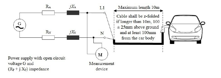
|
a0c0 |
| A12 | Figure 1b | a0c0 |
| A12 |
Vehicle in configuration "REESS charging mode coupled to the power grid" - Three phase test set-up |
a0c0 |
| A12 |
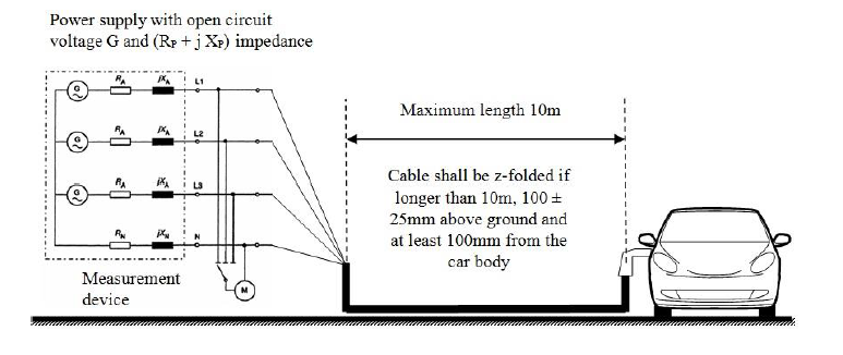
|
a0c0 |
| A13 |
|
a0c0 |
| A13 |
|
a0c0 |
| A13 1. | General | a0c0 |
| A13 1.1. | The test method described in this annex shall be applied to vehicles in configuration "REESS charging mode coupled to the power grid". | a0c0 |
| A13 1.2. | Test method | a0c0 |
| A13 | This test is intended to measure the level of radio frequency conducted disturbances generated by vehicle in configuration "REESS charging mode coupled to the power grid" through its AC or DC power lines in order to ensure it is compatible with residential, commercial and light industrial environments. | a0c0 |
| A13 | If not otherwise stated in this annex the test shall be performed according to CISPR 16-2-1. | a0c0 |
| A13 2. | Vehicle state during tests | a0c0 |
| A13 2.1. | The vehicle shall be in configuration "REESS charging mode coupled to the power grid". | a0c0 |
| A13 | The state of charge (SOC) of the traction battery shall be kept between 20 per cent and 80 per cent of the maximum SOC during the whole frequency range measurement (this may lead to split the measurement in different sub-bands with the need to discharge the vehicle's traction battery before starting the next sub-bands). If the current consumption can be adjusted, then the current shall be set to at least 80 per cent of its nominal value. | a0c0 |
| A13 | The vehicle shall be immobilized, engine OFF. | a0c0 |
| A13 | And all other equipment which can be switched on permanently by the driver or passenger should be OFF. | a0c0 |
| A13 3. | Test arrangements | a0c0 |
| A13 3.1. | The test shall be performed according to paragraph 7.4.1. of CISPR 16-2-1 as floor-standing equipment. | a0c0 |
| A13 3.2. | The artificial mains network to be used for the measurement on vehicle is defined in paragraph 4.3. of CISPR 16-1-2. | a0c0 |
| A13 | Artificial networks | a0c0 |
| A13 | The AN(s) shall be mounted directly on the ground plane. The cases of the AN(s) shall be bonded to the ground plane. | a0c0 |
| A13 | The measuring port of each AN shall be terminated with a 50 Ω load. | a0c0 |
| A13 | The AN shall be placed as defined in Figures 1a to 1d. of Appendix 1 to this annex. | a0c0 |
| A13 3.3. | The test set-up for the connection of the vehicle in configuration "REESS charging mode coupled to the power grid" is shown in Figure 1a to 1d of Appendix 1 to this annex. | a0c0 |
| A13 3.4. | The measurements shall be performed with a spectrum analyser or a scanning receiver. The parameters to be used are defined in Table 1 and Table 2. | a0c0 |
| A13 | Table 1 | a0c0 |
| A13 | Spectrum analyser parameters | a0c0 |
| A13 |
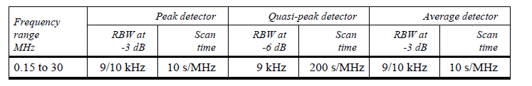
|
a0c0 |
| A13 | Note: If a spectrum analyser is used for peak measurements, the video bandwidth shall be at least three times the resolution bandwidth (RBW) | a0c0 |
| A13 | Table 2 | a0c0 |
| A13 | Scanning receiver parameters | a0c0 |
| A13 |

|
a0c0 |
| A13 | a For purely broadband disturbances, the maximum frequency step size may be increased up to a value not greater than the bandwidth value. | a0c0 |
| A13 4. | Test requirements | a0c0 |
| A13 4.1. | The limits apply throughout the frequency range 0.15 to 30 MHz for measurements performed in a semi anechoic chamber or an outdoor test site. | a0c0 |
| A13 4.2. | Measurements shall be performed with average and either quasi-peak or peak detectors. The limits are given in paragraph 7.5. of this Regulation. | a0c0 |
| A13 | Table 7 for AC lines and Table 8 for DC lines. If peak detectors are used a correction factor of 20 dB as defined in CISPR 12 shall be applied. | a0c0 |
| A13 |
|
a0c0 |
| A13 | Figure 1 | a0c0 |
| A13 | Vehicle in configuration "REESS charging mode coupled to the power grid" | a0c0 |
| A13 | Example of test setup for vehicle with plug located on vehicle side (AC powered without communication) | a0c0 |
| A13 | Figure 1a | a0c0 |
| A13 |
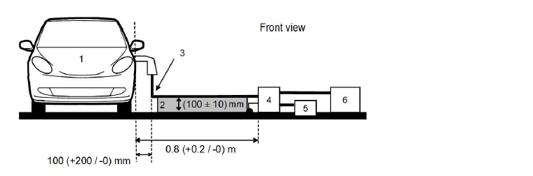
|
a0c0 |
| A13 | Figure1b | a0c0 |
| A13 |
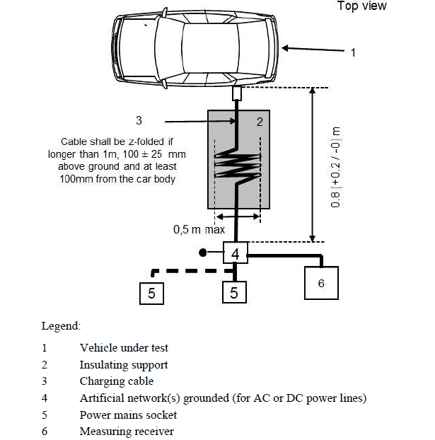
|
a0c0 |
| A13 | Vehicle in configuration "REESS charging mode coupled to the power grid" | a0c0 |
| A13 | Example of test setup for vehicle with plug located front / rear of vehicle (AC powered without communication) | a0c0 |
| A13 | Figure 1c | a0c0 |
| A13 |
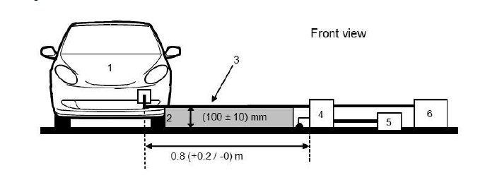
|
a0c0 |
| A13 | Figure 1d | a0c0 |
| A13 |
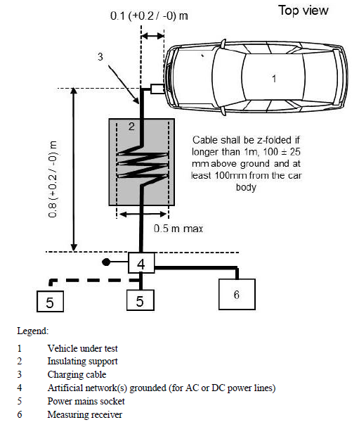
|
a0c0 |
| A14 |
|
a0c0 |
| A14 |
|
a0c0 |
| A14 1. | General | a0c0 |
| A14 1.1. | The test method described in this annex shall be applied to vehicles in configuration "REESS charging mode coupled to the power grid". | a0c0 |
| A14 1.2. | Test method | a0c0 |
| A14 | This test is intended to measure the level of radio frequency conducted disturbances generated by vehicle in configuration "REESS charging mode coupled to the power grid" through its network and telecommunication access in order to ensure it is compatible with residential, commercial and light industrial environments. | a0c0 |
| A14 | If not otherwise stated in this annex the test shall be performed according to CISPR 22. | a0c0 |
| A14 2. | Vehicle/ state during tests | a0c0 |
| A14 2.1. | The vehicle shall be in configuration "REESS charging mode coupled to the power grid". The state of charge (SOC) of the traction battery shall be kept between 20 per cent and 80 per cent of the maximum SOC during the whole frequency range measurement (this may lead to split the measurement in different sub-bands with the need to discharge the vehicle's traction battery before starting the next sub-bands). If the current consumption can be adjusted, then the current shall be set to at least 80 per cent of its nominal value. | a0c0 |
| A14 | The vehicle shall be immobilized, engine OFF. | a0c0 |
| A14 | And all other equipment which can be switched on permanently by the driver or passenger should be OFF. | a0c0 |
| A14 3. | Test arrangements | a0c0 |
| A14 3.1. | The test set-up shall be performed according to paragraph 5. of CISPR 22 for conducted emissions. | a0c0 |
| A14 3.2. | The impedance stabilisation to be used for the measurement on vehicle is defined in paragraph 9.6.2. of CISPR 22. | a0c0 |
| A14 | Impedance Stabilization | a0c0 |
| A14 | Communication lines shall be applied to the vehicle through IS(s). | a0c0 |
| A14 | The IS(s) shall be mounted directly on the ground plane. The case of the IS(s) shall be bonded to the ground plane. | a0c0 |
| A14 | The measuring port of each IS shall be terminated with a 50 Ω load. The IS shall be placed as defined in Figures 1a to 1d of Appendix 1 to this annex. | a0c0 |
| A14 3.3. | The test set-up for the connection of the vehicle in configuration "REESS charging mode coupled to the power grid" is shown in Figures 1a to 1d of Appendix 1 to this annex. | a0c0 |
| A14 | If it is impossible to guarantee the functionality of vehicle, due to introduction of IS, an alternate method described in CISPR 22 (according to Figures 2a to 2d of Appendix 1 to this annex) shall be applied. | a0c0 |
| A14 3.4. | The measurements shall be performed with a spectrum analyser or a scanning receiver. The parameters to be used are defined in Table 1 and Table 2. | a0c0 |
| A14 | Table 1 | a0c0 |
| A14 | Spectrum analyser parameters | a0c0 |
| A14 |
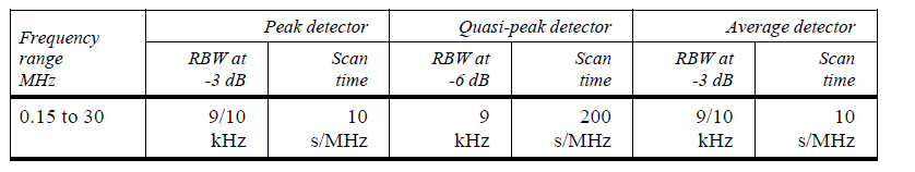
|
a0c0 |
| A14 | Note: If a spectrum analyser is used for peak measurements, the video bandwidth shall be at least three times the resolution bandwidth (RBW) | a0c0 |
| A14 | Table 2 | a0c0 |
| A14 | Scanning receiver parameters | a0c0 |
| A14 |
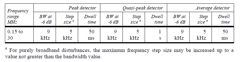
|
a0c0 |
| A14 | a For purely broadband disturbances, the maximum frequency step size may be increased up to a value not greater than the bandwidth value. | a0c0 |
| A14 4. | Test requirements | a0c0 |
| A14 4.1. | The limits apply throughout the frequency range 0.15 to 30 MHz for measurements performed in a semi anechoic chamber or an outdoor test site. | a0c0 |
| A14 4.2. | Measurements shall be performed with average and either quasi-peak or peak detectors. The limits are given in Table 9 of paragraph 7.6. If peak detectors are used a correction factor of 20 dB as defined in CISPR 12 shall be applied. | a0c0 |
| A14 |
|
a0c0 |
| A14 | Figure 1 | a0c0 |
| A14 | Vehicle in configuration "REESS charging mode coupled to the power grid" | a0c0 |
| A14 | Example of test setup for vehicle with plug located on vehicle side (AC or DC powered with communication) | a0c0 |
| A14 | Figure 1a | a0c0 |
| A14 |
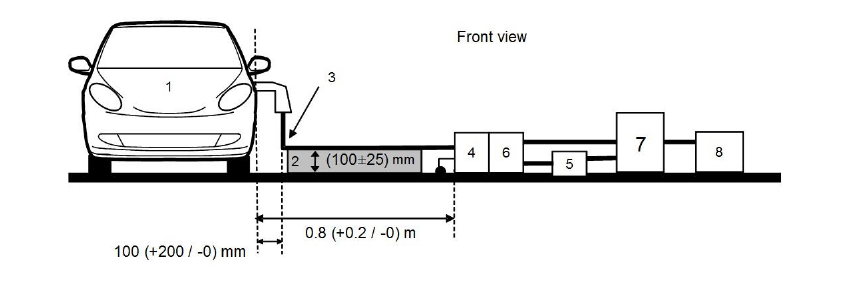
|
a0c0 |
| A14 | Figure 1b | a0c0 |
| A14 |

|
a0c0 |
| A14 | Vehicle in configuration "REESS charging mode coupled to the power grid" | a0c0 |
| A14 | Example of test set-up for vehicle with plug located front/rear of vehicle (AC or DC powered with communication) | a0c0 |
| A14 | Figure 1c | a0c0 |
| A14 |

|
a0c0 |
| A14 | Figure 1d | a0c0 |
| A14 |
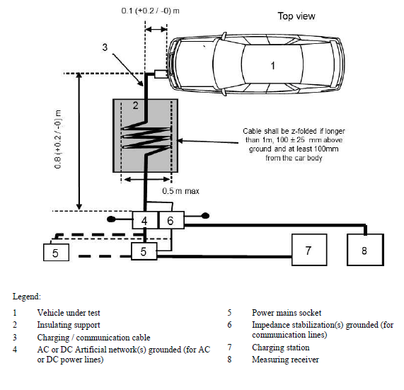
|
a0c0 |
| A14 | Figure 2 | a0c0 |
| A14 | Alternative measurement for vehicle in configuration "REESS charging mode coupled in the power grid" | a0c0 |
| A14 | Example of test setup for vehicle with plug located on vehicle side (AC or DC powered with communication) | a0c0 |
| A14 | Figure 2a | a0c0 |
| A14 |
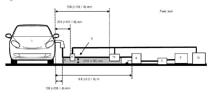
|
a0c0 |
| A14 | Figure 2b | a0c0 |
| A14 |

|
a0c0 |
| A14 | Alternative measurement for vehicle in configuration "REESS charging mode coupled in the power grid" | a0c0 |
| A14 | Example of test setup for vehicle with plug located front / rear of vehicle (AC or DC powered with communication) | a0c0 |
| A14 | Figure 2c | a0c0 |
| A14 |

|
a0c0 |
| A14 | Figure 2d | a0c0 |
| A14 |

|
a0c0 |
| A15 |
|
a0c0 |
| A15 |
|
a0c0 |
| A15 1. | General | a0c0 |
| A15 1.1. | The test method described in this annex shall only be applied to vehicles. This method concerns only the configuration of the vehicle with "REESS charging mode coupled to the power grid". | a0c0 |
| A15 1.2. | Test method | a0c0 |
| A15 | This test is intended to demonstrate the immunity of the vehicle electronic systems. The vehicle shall be subject to electrical fast transient/burst disturbances conducted along AC and DC power lines of the vehicle as described in this annex. The vehicle shall be monitored during the tests. | a0c0 |
| A15 | If not otherwise stated in this annex the test shall be performed according to IEC 61000-4-4. | a0c0 |
| A15 2. | Vehicle state during tests in configuration "REESS in charging mode coupled to the power grid" | a0c0 |
| A15 2.1. | The vehicle shall be in an unladen condition except for necessary test equipment. | a0c0 |
| A15 2.1.1. | The vehicle shall be immobilized, engine OFF and in charging mode. | a0c0 |
| A15 2.1.2. | Basic vehicle conditions | a0c0 |
| A15 | The paragraph defines minimum test conditions (as far as applicable) and failures criteria for vehicle immunity tests. Other vehicle systems, which can affect immunity related functions, shall be tested in a way to be agreed between manufacturer and Technical Service. | a0c0 |
| A15 |
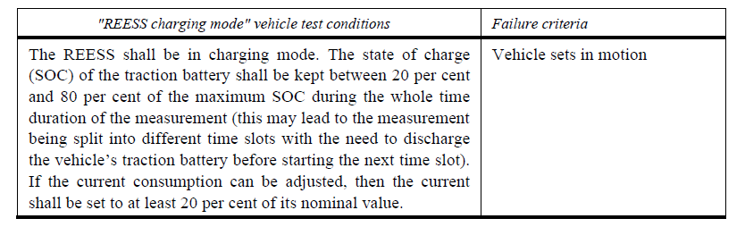
|
a0c0 |
| A15 2.1.3. | All other equipment which can be switched on permanently by the driver or passenger should be OFF. | a0c0 |
| A15 2.2. | Only non-perturbing equipment shall be used while monitoring the vehicle. The vehicle exterior and the passenger compartment shall be monitored to determine whether the requirements of this annex are met (e.g. by using (a) video camera(s), a microphone, etc.). | a0c0 |
| A15 3. | Test equipment | a0c0 |
| A15 3.1. | The test equipment is composed of a reference ground plane (a shielded room is not required), a transient/burst generator, Coupling/Decoupling Network (CDN) and capacitive coupling clamp. | a0c0 |
| A15 3.2. |
The transient/burst generator shall meet the condition defined in paragraph 6.1. of IEC 61000-4-4. |
a0c0 |
| A15 3.3. | The Coupling/Decoupling Network shall meet the condition defined in paragraph 6.2. of IEC 61000-4-4. When the Coupling/Decoupling Network cannot be used on AC or DC power lines, the capacitive coupling clamp defined in paragraph 6.3. of IEC 61000-4-4 can be used. | a0c0 |
| A15 4. | Test setup | a0c0 |
| A15 4.1. | The vehicle test setup is based on the laboratory type setup as described in paragraph 7.2. of IEC 61000-4-4. | a0c0 |
| A15 4.2. | The vehicle shall be placed directly on the ground plane. | a0c0 |
| A15 4.3. | The Technical Service shall perform the test as specified in paragraph 7.7.2.1. of this Regulation. | a0c0 |
| A15 | Alternatively, if the manufacturer provides measurement from a test laboratory accredited to the applicable parts of ISO 17025 and recognized by the Type Approval Authority, the Technical Service may choose not to perform the test to confirm that the vehicle meets the requirements of this annex. | a0c0 |
| A15 5. | Generation of required test level | a0c0 |
| A15 5.1. | Test methodology | a0c0 |
| A15 5.1.1. | The test method according to IEC 61000-4-4 shall be used to establish the test level requirements. | a0c0 |
| A15 5.1.2. | Test phase | a0c0 |
| A15 | The vehicle shall be positioned on the ground plane. The electrical fast transient/burst (EFT/B) shall be applied on the vehicle on the AC/DC power lines in common modes by using CDN as described in Figure 1 of Appendix 1 to this annex. | a0c0 |
| A15 | The test set-up shall be noted in the test report. | a0c0 |
| A15 |
|
a0c0 |
| A15 | Figure 1 | a0c0 |
| A15 | Vehicle in configuration "REESS charging mode" coupled to the power grid coupling on AC/DC power lines | a0c0 |
| A15 |

|
a0c0 |
| A16 |
|
a0c0 |
| A16 |
|
a0c0 |
| A16 1. | General | a0c0 |
| A16 1.1. | The test method described in this annex shall only be applied to vehicles. This method concerns only the configuration of the vehicle with "REESS charging mode coupled to the power grid". | a0c0 |
| A16 1.2. | Test method | a0c0 |
| A16 | This test is intended to demonstrate the immunity of the vehicle electronic systems. The vehicle shall be subject to surges conducted along AC and DC power lines of the vehicle as described in this annex. The vehicle shall be monitored during the tests. | a0c0 |
| A16 | If not otherwise stated in this annex the test shall be performed according to IEC 61000-4-5. | a0c0 |
| A16 2. | Vehicle state during tests in configuration "REESS in charging mode coupled to the power grid" | a0c0 |
| A16 2.1. | The vehicle shall be in an unladen condition except for necessary test equipment. | a0c0 |
| A16 2.1.1. | The vehicle shall be immobilized, engine OFF and in charging mode. | a0c0 |
| A16 2.1.2. | Basic vehicle conditions | a0c0 |
| A16 | The paragraph defines minimum test conditions (as far as applicable) and failures criteria for vehicle immunity tests. Other vehicle systems, which can affect immunity related functions, shall be tested in a way to be agreed between manufacturer and Technical Service. | a0c0 |
| A16 |
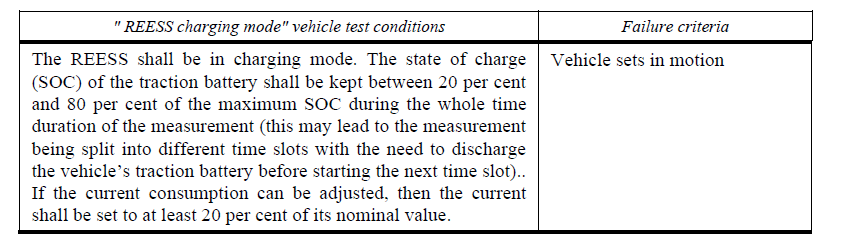
|
a0c0 |
| A16 2.1.3. | All other equipment which can be switched on permanently by the driver or passenger should be OFF. | a0c0 |
| A16 2.2. | Only non-perturbing equipment shall be used while monitoring the vehicle. The vehicle exterior and the passenger compartment shall be monitored to determine whether the requirements of this annex are met (e.g. by using (a) video camera(s), a microphone, etc.). | a0c0 |
| A16 3. | Test equipment | a0c0 |
| A16 3.1. | The test equipment is composed of a reference ground plane (a shielded room is not required), a surge generator and a Coupling/Decoupling Network (CDN). | a0c0 |
| A16 3.2. |
The surge generator shall meet the condition defined in paragraph 6.1. of IEC 61000-4-5. |
a0c0 |
| A16 3.3. | The Coupling/Decoupling Network shall meet the condition defined in paragraph 6.3. of IEC 61000-4-5. | a0c0 |
| A16 4. | Test setup | a0c0 |
| A16 4.1. |
The vehicle test setup is based on the setup described in paragraph 7.2. of IEC 61000-4-5. |
a0c0 |
| A16 4.2. | The vehicle shall be placed directly on the ground plane. | a0c0 |
| A16 4.3. | The Technical Service shall perform the test as specified in paragraph 7.8.2.1. of this Regulation. | a0c0 |
| A16 | Alternatively, if the manufacturer provides measurement from a test laboratory accredited to the applicable parts of ISO 17025 and recognized by the Type Approval Authority, the Technical Service may choose not to perform the test to confirm that the vehicle meets the requirements of this annex. | a0c0 |
| A16 5. | Generation of required test level | a0c0 |
| A16 5.1. | Test methodology | a0c0 |
| A16 5.1.1. | The test method according to IEC 61000-4-5 shall be used to establish the test level requirements. | a0c0 |
| A16 5.1.2. | Test phase | a0c0 |
| A16 | The vehicle shall be positioned on the ground plane. The electrical surge shall be applied on the vehicle on the AC/DC power lines between each line and earth and between lines by using CDN as described in Figures 1 to 4 of Appendix 1 to this annex, | a0c0 |
| A16 | The test setup shall be noted in the test report. | a0c0 |
| A16 |
|
a0c0 |
| A16 |
|
a0c0 |
| A16 | Figure 1 | a0c0 |
| A16 |
Vehicle in configuration "REESS charging mode coupled to the power grid" - Coupling between lines for DC or AC (single phase) power lines |
a0c0 |
| A16 |

|
a0c0 |
| A16 | Figure 2 | a0c0 |
| A16 |
Vehicle in configuration "REESS charging mode coupled to the power grid" - Coupling between each line and earth for DC or AC (single phase) power lines |
a0c0 |
| A16 |
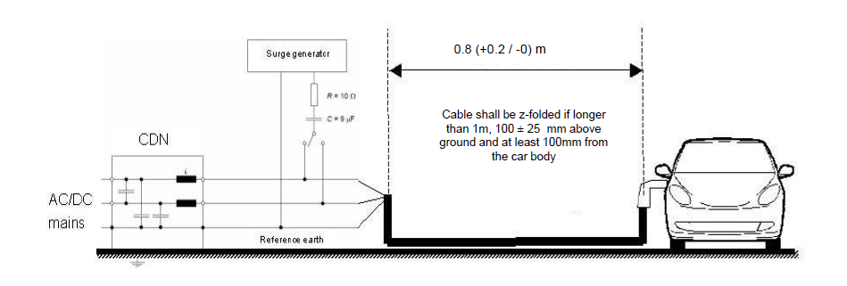
|
a0c0 |
| A16 | Figure 3 | a0c0 |
| A16 |
Vehicle in configuration "REESS charging mode coupled to the power grid" - Coupling between lines for AC (three phases) power lines |
a0c0 |
| A16 |
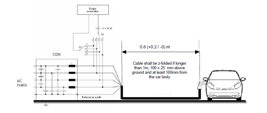
|
a0c0 |
| A16 | Figure 4 | a0c0 |
| A16 |
Vehicle in configuration "REESS charging mode coupled to the power grid" - Coupling between each line and earth for AC (three phases) power lines |
a0c0 |
| A16 |
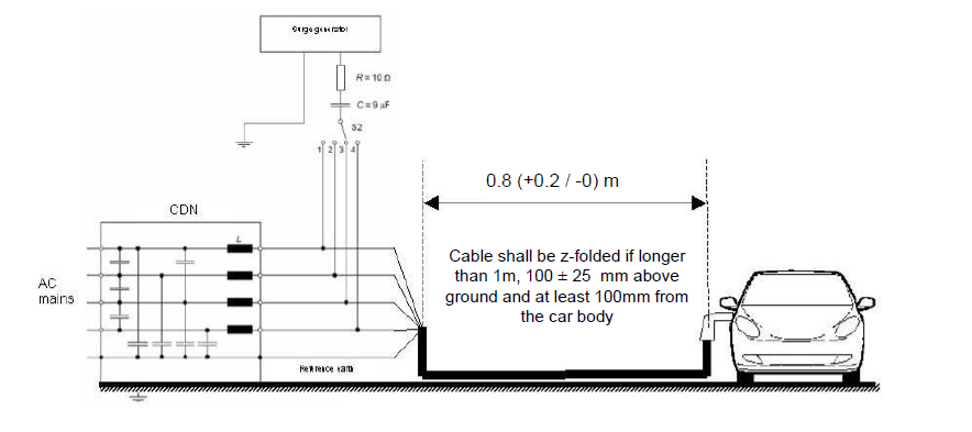
|
a0c0 |
| A17 |
|
a0c0 |
| A17 |
|
a0c0 |
| A17 1. | General | a0c0 |
| A17 1.1. | The test method described in this annex shall be applied to ESAs in configuration "REESS charging mode coupled to the power grid" | a0c0 |
| A17 1.2. | Test method | a0c0 |
| A17 | This test is intended to measure the level of harmonics generated by an ESA in configuration "REESS charging mode coupled to the power grid" through its AC power lines in order to ensure it is compatible with residential, commercial and light industrial environments. | a0c0 |
| A17 | If not otherwise stated in this annex the test shall be performed according to: | a0c0 |
| A17 | (a) IEC 61000-3-2 for input current in charging mode ≤ 16 A per phase for class A equipment; | a0c0 |
| A17 | (b) IEC 61000-3-12 for input current in charging mode > 16 A and ≤ 75 A per phase. | a0c0 |
| A17 2. | ESA state during tests | a0c0 |
| A17 2.1. | The ESA shall be in configuration "REESS charging mode coupled to the power grid". | a0c0 |
| A17 |
The state of charge (SOC) of the traction battery shall be kept between 20 per cent and 80 per cent of the maximum SOC during the whole time duration of the measurement (this may lead to the measurement being split into different time slots with the need to discharge the vehicle's traction battery before starting the next time slot). |
a0c0 |
| A17 | If the current consumption can be adjusted, then the current shall be set to at least 80 per cent of its nominal value. | a0c0 |
| A17 3. | Test arrangements | a0c0 |
| A17 3.1. | The observation time to be used for the measurements shall be as for quasi-stationary equipment as defined in Table 4 of IEC 61000-3-2. | a0c0 |
| A17 3.2. | The test set-up for single phase ESA in configuration "REESS charging mode coupled to the power grid" is shown in Figure 1 of Appendix 1 to this annex. | a0c0 |
| A17 3.3. | The test set-up for three-phase ESA in configuration "REESS charging mode coupled to the power grid" is shown in Figure 2 of Appendix 1 to this annex. | a0c0 |
| A17 4. | Test requirements | a0c0 |
| A17 4.1. | The measurements of even and odd current harmonics shall be performed up to the 40th harmonic. | a0c0 |
| A17 4.2. | The limits for single phase or three-phase ESAs in configuration "REESS charging mode coupled to the power grid" with input current ≤ 16 A per phase are given in Table 10 of paragraph 7.11.2.1. of this Regulation. | a0c0 |
| A17 4.3. | The limits for single phase ESAs in configuration "REESS charging mode coupled to the power grid" with input current > 16 A and ≤ 75 A per phase are given in Table 11 of paragraph 7.11.2.2. of this Regulation. | a0c0 |
| A17 4.4. | The limits for three-phase ESAs in configuration "REESS charging mode coupled to the power grid" with input current > 16 A and ≤ 75 A per phase are given in paragraph Table 12 of 7.11.2.2. of this Regulation. | a0c0 |
| A17 4.5. | For three-phase ESAs in configuration "REESS charging mode coupled to the power grid" with input current > 16 A and ≤ 75 A per phase, when at least one of the three conditions a), b) or c) described in paragraph 5.2. of | a0c0 |
| A17 |
IEC 61000-3-12 is fulfilled, then the limits given in Table 13 of paragraph 7.11.2.2. of this Regulation can be applied. |
a0c0 |
| A17 |
|
a0c0 |
| A17 | Figure 1 | a0c0 |
| A17 |
ESA in configuration "REESS charging mode coupled to the power grid" - Single phase test set-up |
a0c0 |
| A17 |
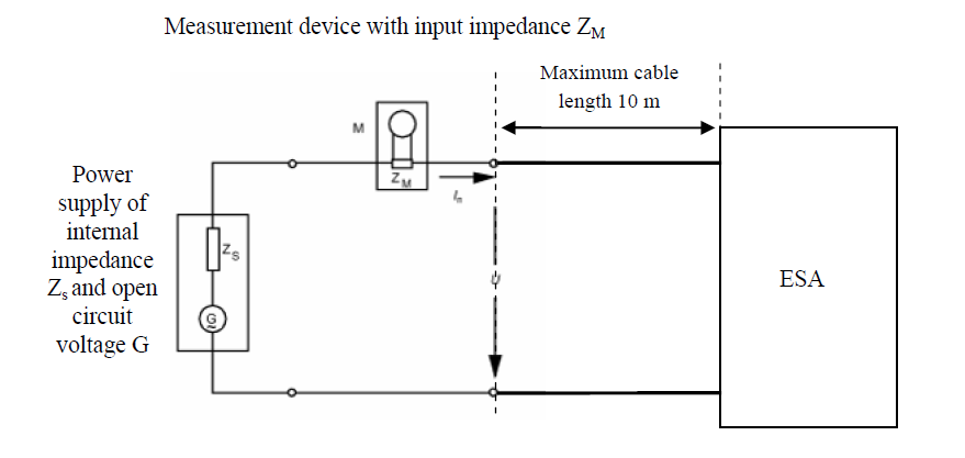
|
a0c0 |
| A17 | Figure 2 | a0c0 |
| A17 |
ESA in configuration "REESS charging mode coupled to the power grid" -Three-phase test set-up |
a0c0 |
| A17 |
|
a0c0 |
| A18 |
|
a0c0 |
| A18 |
|
a0c0 |
| A18 1. | General | a0c0 |
| A18 1.1. | The test method described in this annex shall be applied to ESAs in configuration "REESS charging mode coupled to the power grid" | a0c0 |
| A18 1.2. | Test method | a0c0 |
| A18 | This test is intended to measure the level of voltage changes, voltage fluctuations and flicker generated by ESA in configuration "REESS charging mode coupled to the power grid" through its AC power lines in order to ensure it is compatible with residential, commercial and light industrial environments. | a0c0 |
| A18 | If not otherwise stated in this annex the test shall be performed according to: | a0c0 |
| A18 |
(a) IEC 61000-3-3 for rated current in "REESS charging mode" ≤ 16 A per phase and not subjected to conditional connection; |
a0c0 |
| A18 | (b) IEC 61000-3-11 for rated current in "REESS charging mode" > 16 A and ≤ 75 A per phase and subjected to conditional connection | a0c0 |
| A18 2. | ESA state during tests | a0c0 |
| A18 2.1. | The ESA shall be in configuration "REESS charging mode coupled to the power grid" | a0c0 |
| A18 |
The state of charge (SOC) of the traction battery shall be kept between 20 per cent and 80 per cent of the maximum SOC during the whole time duration of the measurement (this may lead to the measurement being split into different time slots with the need to discharge the vehicle's traction battery before starting the next time slot). |
a0c0 |
| A18 | If the current consumption can be adjusted, then the current shall be set to at least 80 per cent of its nominal value. | a0c0 |
| A18 3. | Test Arrangements | a0c0 |
| A18 3.1. | The tests for ESA in configuration "REESS charging mode coupled to the power grid" with rated current ≤ 16 A per phase and not subjected to conditional connection shall be performed according to paragraph 4. of IEC 61000-3-3. | a0c0 |
| A18 3.2. | The tests for ESA in configuration "REESS charging mode coupled to the power grid" with rated current > 16 A and ≤ 75 A per phase and subjected to conditional connection shall be performed according to paragraph 6. of IEC 61000-3-11. | a0c0 |
| A18 3.3. | The test set-up for ESA in configuration "REESS charging mode coupled to the power grid" is shown in Figures 1a and 1b of Appendix 1 to this annex. | a0c0 |
| A18 4. | Test requirements | a0c0 |
| A18 4.1. | The parameters to be determined in the time-domain are "short duration flicker value", "long duration flicker value" and "voltage relative variation". | a0c0 |
| A18 4.2. | The limits for ESA in configuration "REESS charging mode coupled to the power grid" with input current ≤ 16 A per phase and not subjected to conditional connection are given in paragraph 7.12.2.1. of this Regulation. | a0c0 |
| A18 4.3. | The limits for ESA in configuration "REESS charging mode coupled to the power grid" with input current > 16 A and ≤ 75 A per phase and subjected to conditional connection are given in paragraph 7.12.2.2. of this Regulation. | a0c0 |
| A18 |
|
a0c0 |
| A18 | Figure 1a | a0c0 |
| A18 | ESA in configuration "REESS charging mode coupled to the power grid"- Single phase test set-up | a0c0 |
| A18 |
|
a0c0 |
| A18 | Figure 1b | a0c0 |
| A18 | ESA in configuration "REESS charging mode coupled to the power grid" - Three-phase test set-up | a0c0 |
| A18 |

|
a0c0 |
| A19 |
|
a0c0 |
| A19 |
|
a0c0 |
| A19 1. | General | a0c0 |
| A19 1.1. | The test method described in this annex shall be applied to ESAs in configuration "REESS charging mode coupled to the power grid". | a0c0 |
| A19 1.2. | Test method | a0c0 |
| A19 | This test is intended to measure the level of radio frequency conducted disturbances generated by ESA in configuration "REESS charging mode coupled to the power grid" through its AC or DC power lines in order to ensure it is compatible with residential, commercial and light industrial environments. | a0c0 |
| A19 | If not otherwise stated in this annex the test shall be performed according to CISPR 16-2-1. | a0c0 |
| A19 2. | ESA state during tests | a0c0 |
| A19 2.1. | The ESA shall be in configuration "REESS charging mode coupled to the power grid". | a0c0 |
| A19 | The state of charge (SOC) of the traction battery shall be kept between 20 per cent and 80 per cent of the maximum SOC during the whole frequency range measurement (this may lead to split the measurement in different sub-bands with the need to discharge the vehicle's traction battery before starting the next sub-bands). | a0c0 |
| A19 | If the test is not performed with a REESS the ESA should be tested at rated current. If the current consumption can be adjusted, then the current shall be set to at least 80 per cent of its nominal value. | a0c0 |
| A19 3. | Test arrangements | a0c0 |
| A19 3.1. | The test shall be performed according to paragraph 7.4.1. of CISPR 16-2-1 as table-standing equipment. | a0c0 |
| A19 3.2. | The artificial mains network to be used for the measurement on vehicle components is defined in paragraph 4.3. of CISPR 16-1-2. | a0c0 |
| A19 | Artificial networks | a0c0 |
| A19 | The AN(s) shall be mounted directly on the ground plane. The cases of the AN(s) shall be bonded to the ground plane. | a0c0 |
| A19 | The conducted emissions on AC and DC power lines are measured successively on each power line by connecting the measuring receiver on the measuring port of the related AN, the measuring port of the AN inserted in the other power lines being terminated with a 50 Ω load. | a0c0 |
| A19 | The AN shall be placed in front, aligned and on the same side of the vehicle power charging plug. | a0c0 |
| A19 3.3. | The test set-up for the connection of the ESAs in configuration "REESS charging mode coupled to the power grid" is shown in Figure 1 of Appendix 1 to this annex. | a0c0 |
| A19 3.4. | The measurements shall be performed with a spectrum analyser or a scanning receiver. The parameters to be used are defined in Table 1 and Table 2. | a0c0 |
| A19 | Table 1 | a0c0 |
| A19 | Spectrum analyser parameters | a0c0 |
| A19 |
|
a0c0 |
| A19 | Note: If a spectrum analyser is used for peak measurements, the video bandwidth shall be at least three times the resolution bandwidth (RBW) | a0c0 |
| A19 | Table 2 | a0c0 |
| A19 | Scanning receiver parameters | a0c0 |
| A19 |
|
a0c0 |
| A19 | a For purely broadband disturbances, the maximum frequency step size may be increased up to a value not greater than the bandwidth value. | a0c0 |
| A19 | Note: For emissions generated by brush commutator motors without an electronic control unit, the maximum step size may be increased up to five times the bandwidth. | a0c0 |
| A19 4. | Test Requirements | a0c0 |
| A19 4.1 | The limits apply throughout the frequency range 0.15 to 30 MHz for measurements performed in a semi anechoic chamber or an outdoor test site. | a0c0 |
| A19 4.2 | Measurements shall be performed with average and either quasi-peak or peak detectors. The limits are given in Table 14 of paragraph 7.13.2.1. of this Regulation for AC lines and in Table 15 of paragraph 7.13.2.2. of this Regulation for DC lines. If peak detectors are used a correction factor of 20 dB as defined in CISPR 12 shall be applied. | a0c0 |
| A19 |
|
a0c0 |
| A19 | Figure 1 | a0c0 |
| A19 | ESA in configuration "REESS charging mode coupled to the power grid" | a0c0 |
| A19 |
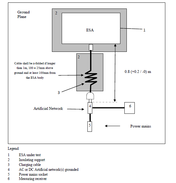
|
a0c0 |
| A20 |
|
a0c0 |
| A20 |
|
a0c0 |
| A20 1. | General | a0c0 |
| A20 1.1. | The test method described in this annex shall be applied to ESAs in configuration "REESS charging mode coupled to the power grid". | a0c0 |
| A20 1.2. | Test method | a0c0 |
| A20 | This test is intended to measure the level of radio frequency conducted disturbances generated by ESA in configuration "REESS charging mode coupled to the power grid" through its network and telecommunication access in order to ensure it is compatible with residential, commercial and light industrial environments. | a0c0 |
| A20 | If not otherwise stated in this annex the test shall be performed according to CISPR 22. | a0c0 |
| A20 2. | ESA state during tests | a0c0 |
| A20 2.1. | The ESA shall be in configuration "REESS charging mode coupled to the power grid". | a0c0 |
| A20 | The state of charge (SOC) of the traction battery shall be kept between 20 per cent and 80 per cent of the maximum SOC during the whole frequency range measurement (this may lead to split the measurement in different sub-bands with the need to discharge the vehicle's traction battery before starting the next sub-bands). | a0c0 |
| A20 | If the test is not performed with a REESS the ESA should be tested at rated current. If the current consumption can be adjusted, then the current shall be set to at least 80 per cent of its nominal value. | a0c0 |
| A20 3. | Test arrangements | a0c0 |
| A20 3.1. | The test set-up shall be performed according to paragraphs 8. and 9. of CISPR 22 for conducted emissions. | a0c0 |
| A20 3.2. | Impedance stabilization | a0c0 |
| A20 | Communication lines shall be applied to the ESA through the Impedance Stabilization(s)s (IS)(s). | a0c0 |
| A20 | IS to be connected in the network and communication cables is defined in paragraph 9.6.2. of CISPR 22. | a0c0 |
| A20 | The IS(s) shall be mounted directly on the ground plane. The case of the IS(s) shall be bonded to the ground plane. | a0c0 |
| A20 | The conducted emissions on network and telecommunication lines are measured successively on each line by connecting the measuring receiver on the measuring port of the related IS, the measuring port of the IS inserted in the other lines being terminated with a 50 Ω load. | a0c0 |
| A20 | The IS shall be placed in front, aligned and on the same side of the vehicle power charging plug. | a0c0 |
| A20 3.3. |
The test set-up for the connection of the ESA in configuration "REESS charging mode coupled to the power grid" is shown in Figure 1 of Appendix 1 to this annex. |
a0c0 |
| A20 3.4. | The measurements shall be performed with a spectrum analyser or a scanning receiver. The parameters to be used are defined in Table 1 and Table 2. | a0c0 |
| A20 | Table 1 | a0c0 |
| A20 | Spectrum analyser parameters | a0c0 |
| A20 |

|
a0c0 |
| A20 | Note: If a spectrum analyser is used for peak measurements, the video bandwidth shall be at least three times the resolution bandwidth (RBW). | a0c0 |
| A20 | Table 2 | a0c0 |
| A20 | Scanning receiver parameters | a0c0 |
| A20 |
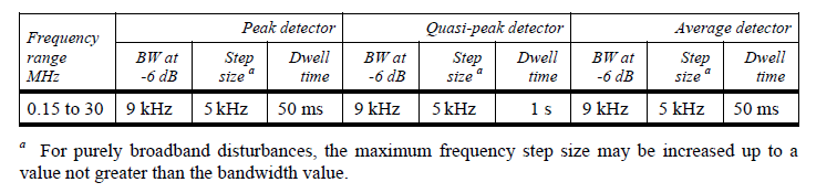
|
a0c0 |
| A20 | a For purely broadband disturbances, the maximum frequency step size may be increased up to a value not greater than the bandwidth value. | a0c0 |
| A20 4. | Test requirements | a0c0 |
| A20 4.1. | The limits apply throughout the frequency range 0.15 to 30 MHz for measurements performed in a semi anechoic chamber or an outdoor test site. | a0c0 |
| A20 4.2. | Measurements shall be performed with average and either quasi-peak or peak detectors. The limits are given in Table 16 of paragraph 7.14.2.1. of this Regulation. If peak detectors are used a correction factor of 20 dB as defined in CISPR 12 shall be applied. | a0c0 |
| A20 |
|
a0c0 |
| A20 | Figure 1 | a0c0 |
| A20 | ESA in configuration "REESS charging mode coupled to the power grid" | a0c0 |
| A20 |
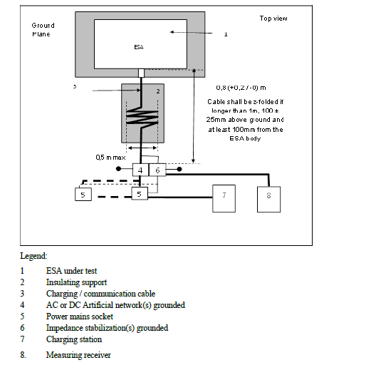
|
a0c0 |
| A21 |
|
a0c0 |
| A21 |
|
a0c0 |
| A21 1. | General | a0c0 |
| A21 1.1. | The test method described in this annex shall only be applied to ESAs. This method applies only to ESA in configuration "REESS charging mode coupled to the power grid". | a0c0 |
| A21 1.2. | Test method | a0c0 |
| A21 | This test is intended to demonstrate the immunity of the ESA. The ESA shall be subject to Electrical Fast Transient/Burst disturbances conducted along AC and DC power lines of the ESA as described in this annex. The ESA shall be monitored during the tests. | a0c0 |
| A21 | If not otherwise stated in this annex the test shall be performed according to IEC 61000-4-4. | a0c0 |
| A21 2. | ESA state during tests in configuration "REESS in charging mode coupled to the power grid" | a0c0 |
| A21 2.1. | Basic ESA conditions | a0c0 |
| A21 | The paragraph defines minimum test conditions (as far as applicable) and failures criteria for ESA immunity tests. | a0c0 |
| A21 |
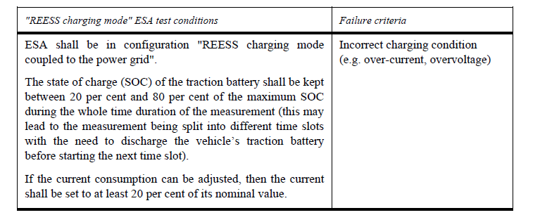
|
a0c0 |
| A21 2.2. | Only non-perturbing equipment shall be used while monitoring the ESA. The ESA shall be monitored to determine whether the requirements of this annex are met (e.g. by using (a) video camera(s), a microphone, etc.). | a0c0 |
| A21 3. | Test equipment | a0c0 |
| A21 3.1. | The test equipment is composed of a reference ground plane (a shielded room is not required), a transient / burst generator, CouplingDecoupling Network (CDN) and capacitive coupling clamp. | a0c0 |
| A21 3.2. |
The transient/burst generator shall meet the condition defined in paragraph 6.1. of IEC 61000-4-4. |
a0c0 |
| A21 3.3. | The Coupling/Decoupling Network shall meet the condition defined in paragraph 6.2. of IEC 61000-4-4. When the Coupling/Decoupling Network cannot be used on AC or DC power lines, the capacitive coupling clamp defined in paragraph 6.3. of IEC 61000-4-4 can be used. | a0c0 |
| A21 4. | Test set-up | a0c0 |
| A21 4.1. | The ESA test setup is based on the laboratory type set-up as described in paragraph 7.2. of IEC 61000-4-4. | a0c0 |
| A21 4.2. | The ESA shall be placed directly on the ground plane. | a0c0 |
| A21 4.3. |
The Technical Service shall perform the test as specified in paragraph 7.15.2.1. of this Regulation. |
a0c0 |
| A21 | Alternatively, if the manufacturer provides measurement from a test laboratory accredited to the applicable parts of ISO 17025 and recognized by the Type Approval Authority, the Technical Service may choose not to perform the test to confirm that the ESA meets the requirements of this annex. | a0c0 |
| A21 5. | Generation of required test level | a0c0 |
| A21 5.1. | Test methodology | a0c0 |
| A21 5.1.1. | The test method according to IEC 61000-4-4 shall be used to establish the test level requirements. | a0c0 |
| A21 5.1.2. | Test phase | a0c0 |
| A21 | The ESA shall be positioned on the ground plane. The Electrical Fast Transient/Burst (EFT/B) shall be applied on the ESA on the AC/DC power lines in common modes by using CDN as described in Figure 1 of Appendix 1 to this annex. | a0c0 |
| A21 | The test setup shall be noted in the test report. | a0c0 |
| A21 |
|
a0c0 |
| A21 | Figure 1 | a0c0 |
| A21 | ESA in configuration "REESS charging mode coupled to the power grid" | a0c0 |
| A21 |
|
a0c0 |
| A22 |
|
a0c0 |
| A22 |
|
a0c0 |
| A22 1. | General | a0c0 |
| A22 1.1. | The test method described in this annex shall only be applied to ESAs. This method applies only to ESAs in configuration "REESS charging mode coupled to the power grid". | a0c0 |
| A22 1.2. | Test method | a0c0 |
| A22 | This test is intended to demonstrate the immunity of the ESA. The ESA shall be subject to surges conducted along AC and DC power lines of the ESA as described in this annex. The ESA shall be monitored during the tests. | a0c0 |
| A22 | If not otherwise stated in this annex the test shall be performed according to IEC 61000-4-5. | a0c0 |
| A22 2. | ESA state during tests in configuration "REESS in charging mode coupled to the power grid" | a0c0 |
| A22 2.1. | The ESA shall be in charging mode. | a0c0 |
| A22 2.1.2. | Basic ESA conditions | a0c0 |
| A22 | The paragraph defines minimum test conditions (as far as applicable) and failures criteria for ESA immunity tests. | a0c0 |
| A22 |

|
a0c0 |
| A22 2.2. | Only non-perturbing equipment shall be used while monitoring the ESA. The ESA shall be monitored to determine whether the requirements of this annex are met (e.g. by using (a) video camera(s), a microphone, etc.). | a0c0 |
| A22 3. | Test equipment | a0c0 |
| A22 3.1. | The test equipment is composed of a reference ground plane (a shielded room is not required), a surge generator and a Coupling/Decoupling Network (CDN). | a0c0 |
| A22 3.2. | The surge generator shall meet the condition defined in paragraph 6.1. of IEC 61000-4-5. | a0c0 |
| A22 3.3. | The Coupling/Decoupling Network shall meet the condition defined in paragraph 6.3. of IEC 61000-4-5. | a0c0 |
| A22 4. | Test set-up | a0c0 |
| A22 4.1. |
The ESA test set-up is based on the set-up described in paragraph 7.2. of IEC 61000-4-5. |
a0c0 |
| A22 4.2. | The ESA shall be placed directly on the ground plane. | a0c0 |
| A22 4.3. | The Technical Service shall perform the test as specified in paragraph 7.16.2.1. of this Regulation. | a0c0 |
| A22 | Alternatively, if the manufacturer provides measurement from a test laboratory accredited to the applicable parts of ISO 17025 and recognized by the Type Approval Authority, the Technical Service may choose not to perform the test to confirm that the ESA meets the requirements of this annex. | a0c0 |
| A22 5. | Generation of required test level | a0c0 |
| A22 5.1. | Test methodology | a0c0 |
| A22 5.1.1. | The test method according to IEC 61000-4-5 shall be used to establish the test level requirements. | a0c0 |
| A22 5.1.2. | Test phase | a0c0 |
| A22 | The ESA shall be positioned on the ground plane. The electrical surge shall be applied on the ESA on the AC/DC power lines between each line and earth and between lines by using CDN as described in Figures 1 to 4 of Appendix 1 to this annex. | a0c0 |
| A22 | The test set-up shall be noted in the test report | a0c0 |
| A22 |
|
a0c0 |
| A22 |
|
a0c0 |
| A22 | Figure 1 | a0c0 |
| A22 | ESA in configuration "REESS charging mode coupled to the power grid" - Coupling between lines for DC or AC (single phase) power lines | a0c0 |
| A22 |
|
a0c0 |
| A22 | Figure 2 | a0c0 |
| A22 | ESA in configuration "REESS charging mode coupled to the power grid" - Coupling between each line and earth for DC or AC (single phase) power lines | a0c0 |
| A22 |

|
a0c0 |
| A22 | Figure 3 | a0c0 |
| A22 | ESA in configuration "REESS charging mode coupled to the power grid" - Coupling between lines for AC (three phases) power lines | a0c0 |
| A22 |
|
a0c0 |
| A22 | Figure 4 | a0c0 |
| A22 | ESA in configuration "REESS charging mode coupled to the power grid" - Coupling between each line and earth for AC (three phases) power lines | a0c0 |
| A22 |

|
a0c0 |