| ... | Regulation | a0c0 |
| ... | 1.Scope | a0c0 |
| ... | 2.Definition: General | a0c0 |
| ... | 3.Application for approval | a0c0 |
| ... | 4.Approval | a0c0 |
| ... | 5.Part I: Approval of a vehicle type with regard to its heating system | a0c0 |
| ... | 6.Part II: Approval of a heating system with regard to its operational safety | a0c0 |
| ... | 7.Modification and extension of approval of a vehicle or component type | a0c0 |
| ... | 8.Conformity of production | a0c0 |
| ... | 9.Penalties for non-conformity of production | a0c0 |
| ... | 10.Production definitely discontinued | a0c0 |
| ... | 11.Names and addresses of technical services conducting approval tests and administrative departments | a0c0 |
| ... | Annexes | a0c0 |
| ... | 1.Information documents and communication forms | a0c0 |
| ... | 2.Arrangements of approval marks | a0c0 |
| ... | 3.Requirements for waste heating systems - AIR | a0c0 |
| ... | 4.Test procedure for air quality | a0c0 |
| ... | 5.Test procedure for temperature | a0c0 |
| ... | 6.Test procedure for exhaust emission of combustion heaters | a0c0 |
| ... | 7.Additional requirements for combustion heaters and their installation | a0c0 |
| ... | 8.Safety requirements for LPG combustion heaters | a0c0 |
| ... | 9.Additional provisions applicable to certain vehicles as specified in the ADR | a0c0 |
| 1. |
|
a0c0 |
| 1.1. | This regulation applies to all vehicles in categories M, N and O 1/ in which a heating system is fitted. | a0c0 |
| ... | Type approvals are granted according to: | a0c0 |
| 1.2. | Part I - Approval of a vehicle type with regard to its heating system. | a0c0 |
| 1.3. | Part II - Approval of a heating system with regard to its operational safety. | a0c0 |
|
|
|
a0c0 |
| 2. |
|
a0c0 |
| ... | For the purposes of this Regulation: | a0c0 |
| 2.1. | "Vehicle" means a vehicle of category M, N or O 1/ in which a heating system is fitted. | a0c0 |
| 2.2. | "Manufacturer" means the person or body who is responsible to the approval authority for all aspects of the type approval process and for ensuring conformity of production. It is not essential that the person or body is directly involved in all stages of the construction of the vehicle or component which is the subject of the approval process. | a0c0 |
| 2.3. | "Interior" means the enclosed parts of a vehicle used for the accommodation of the vehicle occupants and/or the load. | a0c0 |
| 2.4. | "Heating system for the passenger compartment" means any type of device designed to increase the temperature of the passenger compartment. | a0c0 |
| 2.5. | "Heating system for the load area" means any type of device designed to increase the temperature of the load area. | a0c0 |
| 2.6. | "Load area" means the interior part of the vehicle used to accommodate the non-passenger load. | a0c0 |
| 2.7. | "Passenger compartment" means the interior part of the vehicle used to accommodate the driver and any passengers. | a0c0 |
| 2.8. | "Gaseous fuel" includes fuels that are gaseous at normal temperature and pressure (288,2 K and 101,33 kPa), such as liquefied petroleum gas (LPG) and compressed natural gas (CNG). | a0c0 |
| 2.9. | "Overheating" means the condition that exists when the air inlet for the heating air to the combustion heater is completely blocked. | a0c0 |
| 3. |
|
a0c0 |
| 3.1. | APPLICATION FOR APPROVAL OF A TYPE OF VEHICLE WITH REGARD TO ITS HEATING SYSTEM | a0c0 |
| 3.1.1. | The application for approval of a vehicle type with regard to its heating system shall be submitted by the manufacturer of the vehicle or by his duly accredited representative. | a0c0 |
| 3.1.2. | It shall be accompanied by the undermentioned documents in triplicate and by the following particulars: | a0c0 |
| 3.1.2.1. | a detailed description of the vehicle type with respect to its structure, dimensions, configuration and constituent materials; | a0c0 |
| 3.1.2.2. | drawings of the heating system and its general arrangement | a0c0 |
| 3.1.3. | A model for the information document is given in Annex 1, Part 1, Appendix 1. | a0c0 |
| 3.1.4. | A vehicle representative of the type to be approved must be submitted to the technical service responsible for conducting the type-approval tests. | a0c0 |
| 3.1.5. | If the vehicle to be approved is equipped with a heater with an ECE type approval, the type approval number and the maker's type designations of this type of heater shall be enclosed in the application for the vehicle type approval. | a0c0 |
| 3.1.6. | If the vehicle to be approved is equipped with a heater without ECE type approval, one sample representative of the type to be approved shall be submitted to the technical service. | a0c0 |
| 3.2. | APPLICATION FOR APPROVAL OF A TYPE OF HEATER | a0c0 |
| 3.2.1. | The application for approval of a type of heater as a component shall be submitted by the manufacturer of the heating system. | a0c0 |
| 3.2.2. | It shall be accompanied by the undermentioned documents in triplicate and by the following particulars: | a0c0 |
| 3.2.2.1. | a detailed description of the heating system type with respect to its structure, dimensions, configuration and constituent materials; | a0c0 |
| 3.2.2.2. | drawings of the heating system and its general arrangement | a0c0 |
| 3.2.3. | A model for the information document is given in Annex 1 Part 1, Appendix 2. | a0c0 |
| 3.2.4. | One sample heater representative of the type to be approved shall be submitted to the technical service. | a0c0 |
| 3.2.5. | The sample shall be clearly and indelibly marked with the applicant's trade name or mark and the type designation. | a0c0 |
| 4. |
|
a0c0 |
| 4.1. | If the type submitted for approval to this Regulation meets the requirements of the relevant part(s) of this Regulation, approval of that type shall be granted. | a0c0 |
| 4.2. | An approval number shall be assigned to each type approved. Its first two digits (at present 00, corresponding to the Regulation in its original form) shall indicate the series of amendments incorporating the most recent major technical amendments made to the Regulation at the time of issue of the approval. The same Contracting Party shall not assign the same number to another type of vehicle or heating system as defined in this Regulation. | a0c0 |
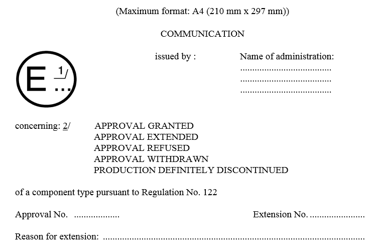
| 4.3. | Notice of approval or of extension of approval of a type pursuant to this Regulation shall be communicated to the Contracting Parties to the Agreement applying this Regulation, by means of one of the forms conforming to the models in Annex 1, Part 2, as appropriate, to this Regulation. | a0c0 |
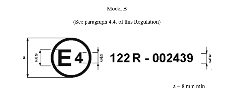
| 4.4. | There shall be affixed, conspicuously and in a readily accessible location specified on the approval form, to every vehicle conforming to a type approved under this Regulation and to every component supplied separately conforming to a type approved under this Regulation, a circle surrounding the letter "E" followed by the distinguishing number of the country which has granted type approval. 2/ | a0c0 |
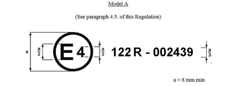
| 4.5. | In the case of a component type-approval, the number of this Regulation, followed by the letter "R", a dash and the approval number according to paragraph 4.2. | a0c0 |
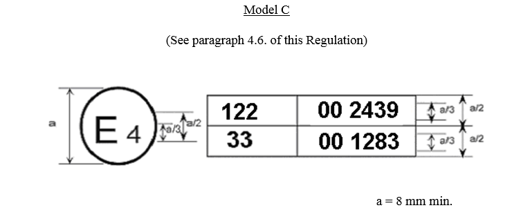
| 4.6. | If a type conforms to a type approved under one or more other Regulations annexed to the Agreement, in the country which has granted approval under this Regulation, the symbol prescribed in paragraph 4.2. needs not be repeated; in such a case, the Regulation(s) under which approval has been granted in the country which has granted approval under this Regulation shall be placed in vertical columns to the right of the symbol prescribed in paragraph 4.2. | a0c0 |
| 4.7. | The approval mark shall be clearly legible and be indelible. | a0c0 |
| 4.8. | In the case of a vehicle, the approval mark shall be placed close to or on the vehicle data plate affixed by the manufacturer. | a0c0 |
| 4.9. | Annex 2 to this Regulation gives examples of arrangements of approval marks. | a0c0 |
|
|
|
a0c0 |
| 5. |
|
a0c0 |
| 5.1. | Definition | a0c0 |
| ... | For the purpose of Part I of this Regulation, | a0c0 |
| 5.1.1. | "Vehicle type with regard to heating system" means vehicles which do not differ in essential respects such as the functioning principle(s) of the heating system. | a0c0 |
| 5.2. | Specifications | a0c0 |
| 5.2.1. | The passenger compartment of every vehicle shall be fitted with a heating system. If a heating system for the load area is provided in a vehicle, it shall comply with this Regulation. | a0c0 |
| 5.2.2. | The heating system of the vehicle to be type approved shall meet the technical requirements of Part II of this Regulation. | a0c0 |
| 5.3. |
Vehicle Installation Requirements for Combustion Heaters |
a2c0 |
| 5.3.1. | Scope | a0c0 |
| 5.3.1.1. |
Subject to paragraph 5.3.1.2., |
a2c0 |
| 5.3.1.2. | Vehicles of category O having liquid fuel heaters are deemed to comply with the requirements of paragraph 5.3. | a0c0 |
| 5.3.2. |
Positioning of |
a2c0 |
| 5.3.2.1. | Body sections and any other components in the vicinity of the heater must be protected from excessive heat and the possibility of fuel or oil contamination. | a0c0 |
| 5.3.2.2. |
The |
a2c0 |
| 5.3.2.3. | In the case of M2 and M3 vehicles, the combustion heater must not be positioned in the passenger compartment. However, an installation in an effectively sealed envelope which also complies with the conditions in paragraph 5.3.2.2. may be used. | a0c0 |
| 5.3.2.4. |
The label referred to in Annex 7, paragraph 1.4, or a duplicate, must be positioned so that it can be easily read when the |
a2c0 |
| 5.3.2.5. | Every reasonable precaution should be taken in positioning the heater to minimize the risk of injury and damage to personal property. | a0c0 |
| 5.3.3. |
Fuel supply |
a2c0 |
| 5.3.3.1. | The fuel filler must not be situated in the passenger compartment and must be provided with an effective cap to prevent fuel spillage. | a0c0 |
| 5.3.3.2. | In the case of liquid fuel heaters, where a supply separate from that of the vehicle is provided, the type of fuel and its filler point must be clearly labelled. | a0c0 |
| 5.3.3.3. | A notice, indicating that the heater must be shut down before refuelling, must be affixed to the fuelling point. In addition a suitable instruction must be included in the manufacturer's operating manual. | a0c0 |
| 5.3.4. |
Exhaust system |
a2c0 |
| 5.3.4.1. | The exhaust outlet must be located so as to prevent emissions from entering the vehicle through ventilators, heated air inlets or opening windows. | a0c0 |
| 5.3.5. |
Combustion air inlet |
a2c0 |
| 5.3.5.1. | The air for the combustion chamber of the heater must not be drawn from the passenger compartment of the vehicle. | a0c0 |
| 5.3.5.2. | The air inlet must be so positioned or guarded that blocking by rubbish or luggage is unlikely. | a0c0 |
| 5.3.6. | Heating air inlet | a0c0 |
| 5.3.6.1. | The heating air supply may be fresh or re-circulated air and must be drawn from a clean area not likely to be contaminated by exhaust fumes emitted either by the propulsion engine, the combustion heater or any other vehicle source. | a0c0 |
| 5.3.6.2. | The inlet duct must be protected by mesh or other suitable means. | a0c0 |
| 5.3.7. | Heating air outlet | a0c0 |
| 5.3.7.1. | Any ducting used to route the hot air through the vehicle must be so positioned or protected that no injury or damage could be caused if it were to be touched. | a0c0 |
| 5.3.7.2. | The air outlet must be so positioned or guarded that blocking by rubbish or luggage is unlikely. | a0c0 |
| 5.3.8. |
Automatic control of the |
a2c0 |
| 5.3.8.1. | The heating system must be switched off automatically and the supply of fuel must be stopped within five seconds when the vehicle's engine stops running. If a manual device is already activated, the heating system can stay in operation. | a0c0 |
| 6. |
|
a0c0 |
| 6.1. | Definitions | a0c0 |
| ... | For the purpose of Part II of this Regulation, | a0c0 |
| 6.1.1. | "Heating system" means any type of device which is designed to increase the temperature of the interior of a vehicle, including any load area. | a0c0 |
| 6.1.2. | "Combustion heater" means a device directly using liquid or gaseous fuel and not using the waste heat from the engine used for propulsion of the vehicle. | a0c0 |
| 6.1.3. |
"Type of |
a2c0 |
| ... |
- |
a2c0 |
| ... | - transfer medium (e.g. air or water), | a0c0 |
| ... | - vehicle location (e.g. passenger compartment or load area). | a0c0 |
| 6.1.4. | "Waste-heat heating system" means any type of device using the waste heat from the engine used for propulsion of the vehicle to increase the temperature of the interior of the vehicle, this may include water, oil or air as the transfer medium. | a0c0 |
|
|
|
a2c0 |
| 6.2. | Specifications: General | a0c0 |
| ... | The requirements for heating systems are that: | a0c0 |
| ... | - the heated air entering the passenger compartment shall be no more polluted than the air at the point of inlet to the vehicle, | a0c0 |
| ... | - the driver and passengers, during road use, will not be able to come into contact with parts of the vehicle or heated air liable to cause burns, | a0c0 |
| ... | - the exhaust emissions from combustion heaters are within acceptable limits. | a0c0 |
| ... | The test procedures for verification of each of these requirements are set out in Annexes 4, 5 and 6. | a0c0 |
| 6.2.1. | The following table indicates which annexes apply to each type of heating system within each vehicle category: | a0c0 |
| ... |

|
a6c0 |
| Note 1: | Heating systems which comply with the requirements of Annex 3 are exempt from these test requirements. | a0c0 |
| Note 2: |
|
a4c0 |
| 6.3. | Specifications: Combustion heaters | a0c0 |
| ... | Additional requirements for combustion heaters are laid down in Annex 7. | a0c0 |
| 7. |
|
a0c0 |
| 7.1. | Every modification of the type shall be notified to the administrative department which approved the type. That department may then either: | a0c0 |
| 7.1.1. | consider that the modifications made are unlikely to have an appreciable adverse effect and that, in any case, the vehicle or component still complies with the requirements; or | a0c0 |
| 7.1.2. | require a further test report from the technical service responsible for conducting the tests. | a0c0 |
| 7.2. | Confirmation or refusal of approval, specifying the modifications, shall be communicated by the procedure specified in paragraph 4.3. to the Contracting Parties to the Agreement which apply this Regulation. | a0c0 |
| 7.3. | The competent authority issuing the extension of approval shall assign a series number for such an extension and inform thereof the other Contracting Parties to the 1958 Agreement applying this Regulation by means of a communication form conforming to the model in Annex 1, Part 2, Appendix 1 or 2 as appropriate to this Regulation. | a0c0 |
| 8. |
|
a0c0 |
| ... | The conformity of production procedures shall comply with those set out in the Agreement, Appendix 2 (E/ECE/324-E/ECE/TRANS/505/Rev.2), with the following requirements: | a0c0 |
| 8.1. | Vehicles and components approved to this regulation shall be so manufactured as to conform to the type approved by meeting the requirements set forth in paragraphs 5. and 6. above. | a0c0 |
| 8.2. | The competent authority which has granted type-approval may at any time verify the conformity control methods applicable to each production facility. The normal frequency of these verifications shall be once per two years. | a0c0 |
| 9. |
|
a0c0 |
| 9.1. | The approval granted in respect of a vehicle type pursuant to this Regulation may be withdrawn if the requirements laid down in paragraphs 5. and 6. above are not complied with. | a0c0 |
| 9.2. | If a Contracting Party to the Agreement applying this Regulation withdraws an approval it has previously granted, it shall forthwith notify the other Contracting Parties applying this Regulation, by means of a communication form conforming to the model in Annex 1, Part 2, Appendix 1 or 2 to this Regulation. | a0c0 |
| 10. |
|
a0c0 |
| ... | If the holder of the approval completely ceases to manufacture a type of vehicle or component under this Regulation, he shall so inform the authority which granted the approval. Upon receiving the relevant communication, that authority shall inform thereof the other Parties to the 1958 Agreement applying this regulation by means of a communication form conforming to the model in Annex 1, Part 2, Appendix 1 or 2 to this Regulation. | a0c0 |
| 11. |
|
a0c0 |
| ... | The Contracting Parties to the Agreement which apply this Regulation shall communicate to the Secretariat of the United Nations the names and addresses of the technical services responsible for conducting approval tests and of the administrative departments which grant approval and to which forms certifying approval or extension or refusal or withdrawal of approval, issued in other countries, are to be sent. | a0c0 |
| A1 |
|
a0c0 |
| A1 | MODEL INFORMATION DOCUMENT | a0c0 |
| A1 | (for a vehicle type in accordance with paragraph 4.3. of the Regulation relating to the ECE Type Approval of a heating system and of a vehicle with regard to its heating system) | a0c0 |
| A1 | If the heating system or its component parts have electronic controls, information concerning their performance must be supplied | a0c0 |
| A1 0. | GENERAL | a0c0 |
| A1 0.1. | Make (trade name of manufacturer): | a0c0 |
| A1 0.2. | Type and general commercial description(s): | a0c0 |
| A1 0.3. | Means of identification of type, if marked on the vehicle: | a0c0 |
| A1 0.4. | Location of that marking: | a0c0 |
| A1 0.5. | Category of vehicle: 1/ | a0c0 |
| A1 0.6. | Name and address of manufacturer: | a0c0 |
| A1 0.7. | Address(es) of assembly plant(s): | a0c0 |
| A1 1. | GENERAL CONSTRUCTION CHARACTERISTICS OF THE VEHICLE | a0c0 |
| A1 1.1. | Photographs and/or drawings of a representative vehicle: | a0c0 |
| A1 2. | POWER PLANT | a0c0 |
| A1 2.1. |
Manufacturer's engine code: (as marked on the engine, or other means of identification) |
a0c0 |
| A1 2.2. | Working principle: positive ignition/compression ignition, four stroke/two stroke 2/ | a0c0 |
| A1 2.3. | Number and arrangement of cylinders: ____________________ | a0c0 |
| A1 2.4. |
Maximum net power: ..........kW at ............min-1 (manufacturer's declared value) |
a0c0 |
| A1 2.5. | Cooling system (liquid/air) 2/ | a0c0 |
| A1 2.6. | Nominal setting of the engine temperature control mechanism: | a0c0 |
| A1 2.7. | Pressure charger: Yes/No 2/ | a0c0 |
| A1 2.7.1. | Type(s) | a0c0 |
| A1 2.7.2. | Description of the system (e.g. maximum charge pressure: ___________kPa, wastegate if applicable) | a0c0 |
| A1 3. | BODYWORK | a0c0 |
| A1 3.1. | A brief description of the vehicle with regard to the heating system if the heating system uses the heat of the engine cooling fluid | a0c0 |
| A1 3.2. | A brief description of the vehicle type with regard to the heating system if the cooling air or the exhaust gases of the engine are used as the heat source, including: | a0c0 |
|
A1 |
Layout of the heating system showing its position in the vehicle: | a0c1 |
|
A1 |
Layout drawing of the heat exchanger for heating systems using the exhaust gases for heating or of the parts where the heat exchange takes place (for heating systems using the engine cooling air for heating): | a0c1 |
|
A1 |
Sectional drawing of the heat exchanger or the parts respectively where the heat exchange takes place, indicating the thickness of the wall, materials used and the characteristics of the surface: | a0c1 |
|
A1 |
Specifications shall be given for further important components of the heating system, such as e.g. the heater fan, with regard to their method of construction and technical data | a0c1 |
|
A1 |
A brief description of the vehicle type with regard to the combustion heating system and the automatic control: | a0c1 |
|
A1 |
layout drawing of the combustion heater, the air inlet system, the exhaust system, the fuel tank, the fuel supply system (including the valves) and the electrical connections showing their positions in the vehicle. | a0c1 |
|
A1 |
Maximum electrical consumption:_________________________kW | a0c1 |
|
A1 |
|
a0c0 |
|
A1 |
|
a0c0 |
| A1 |
|
a0c0 |
| A1 | MODEL INFORMATION DOCUMENT | a0c0 |
| A1 | (for a heating system type in accordance with paragraph 4.3. of the Regulation relating to the ECE Type approval of heating system with regard to its operational safety) | a0c0 |
| A1 | If the heating system or its component parts have electronic controls, information concerning their performance must be supplied | a0c0 |
| A1 1. | GENERAL | a0c0 |
| A1 1.1. | Make (trade name of manufacturer): | a0c0 |
| A1 1.2. | Type and general commercial description(s): | a0c0 |
| A1 1.3. | Name and address of manufacturer: | a0c0 |
| A1 1.4. | In the case of components, location and method of affixing of the ECE approval mark: | a0c0 |
| A1 1.5. | Address(es) of assembly plant(s): | a0c0 |
| A1 2. | COMBUSTION HEATER (IF ANY) | a0c0 |
| A1 2.1. | Make (trade name of manufacturer): ........ | a0c0 |
| A1 2.2. | Type and general commercial description(s): | a0c0 |
| A1 2.3. | Means of identification of type, if marked on the heating system: | a0c0 |
| A1 2.4. | Location of that marking: | a0c0 |
| A1 2.5. | Name and address of manufacturer: | a0c0 |
| A1 2.6. | Address(es) of assembly plant(s): | a0c0 |
| A1 2.7. | Test pressure (in the case of a combustion heater fuelled by liquefied petroleum gas or similar, the pressure applied at the gas inlet connector of the heater): | a0c0 |
| A1 2.8. | Detailed description, layout drawings and mounting description of the combustion heater and all its components: | a0c0 |
| A1 |
|
a0c0 |
| A1 |

|
a0c0 |
| A1 | SECTION I | a0c0 |
| A1 | GENERAL | a0c0 |
| A1 1.1. | Make (trade name of manufacturer): | a0c0 |
| A1 1.2. | Type: | a0c0 |
| A1 1.3. | Means of identification of type, if marked on the vehicle/component/ separate technical unit 2/ b/: | a0c0 |
| A1 1.3.1. | Location of that marking: | a0c0 |
| A1 1.4. | Category of vehicle c/: | a0c0 |
| A1 1.5. | Name and address of manufacturer: | a0c0 |
| A1 1.6. | Location of the ECE approval mark: | a0c0 |
| A1 1.7. | Address(es) of assembly plant(s): | a0c0 |
| A1 | SECTION II | a0c0 |
| A1 1. | Additional information (where applicable) | a0c0 |
| A1 2. | Technical service responsible for carrying out the tests: | a0c0 |
| A1 3. | Date of test report: | a0c0 |
| A1 4. | Number of test report: | a0c0 |
| A1 5. | Remarks (if any): | a0c0 |
| A1 6. | Place: | a0c0 |
| A1 7. | Date: | a0c0 |
| A1 8. | Signature: | a0c0 |
| A1 9. | The index to the information package lodged with the approval authority, which may be obtained on request, is attached. | a0c0 |
| A1 10. | The vehicle is approved according to the requirements of Annex 9 (ADR): Yes/No 2/. | a0c0 |
|
A1 |
|
a0c0 |
|
A1 |
|
a0c0 |
|
A1 |
|
a0c0 |
|
A1 |
|
a0c0 |
| A1 |
|
a0c0 |
| A1 |
|
a0c0 |
| A1 | SECTION I | a0c0 |
| A1 | GENERAL | a0c0 |
| A1 1.1. | Make (trade name of manufacturer): | a0c0 |
| A1 1.2. | Type: | a0c0 |
| A1 1.3. | Means of identification of type, if marked on the device b/: ... | a0c0 |
| A1 1.3.1. | Location of that marking: | a0c0 |
| A1 1.4. | Name and address of manufacturer: | a0c0 |
| A1 1.5. | Location of the ECE approval mark: | a0c0 |
| A1 1.6. | Address(es) of assembly plant(s): | a0c0 |
| A1 | SECTION II | a0c0 |
| A1 | Additional information (where applicable) | a0c0 |
| A1 1. | Technical service responsible for carrying out the tests: | a0c0 |
| A1 2. | Date of test report: | a0c0 |
| A1 3. | Number of test report: | a0c0 |
| A1 4. | Remarks (if any): | a0c0 |
| A1 5. | Place: | a0c0 |
| A1 6. | Date: | a0c0 |
| A1 7. | Signature: | a0c0 |
| A1 8. | The index to the information package lodged with the approval authority, which may be obtained on request, is attached. | a0c0 |
|
A1 |
|
a0c0 |
|
A1 |
|
a0c0 |
|
A1 |
|
a0c0 |
| A2 |
|
a0c0 |
| A2 |
|
a0c0 |
| A2 | The above approval mark affixed to a heating system shows that the component type concerned has, with regard to its constructional features, been approved in the Netherlands (E 4) pursuant to Regulation No. 122 under approval number 002439. The approval number indicates that the approval was granted according to the requirements of Regulation No. 122 in its original form. | a0c0 |
| A2 |
|
a0c0 |
| A2 | The above approval mark affixed to a vehicle shows that the vehicle type concerned has, with regard to its heating system(s), been approved in the Netherlands (E 4) for Class III, pursuant to Regulation No. 122. The number 00 indicates that the approval was granted according to the requirements of Regulation No. 122 in its original form. | a0c0 |
| A2 |
|
a0c0 |
| A2 | The above approval mark affixed to a vehicle shows that the vehicle type concerned has been approved in the Netherlands (E 4) pursuant to Regulations Nos. 122 and 33.*/ The numbers 00 indicate that, at the dates when the respective approvals were given, both Regulations were in their original forms. | a0c0 |
|
A2 |
|
a0c0 |
| A3 |
|
a0c0 |
| A3 1. | The requirements set out in paragraph 6.2. of this Regulation are considered satisfied in respect of heating systems which include a heat exchanger, the primary circuit of which is passed over by exhaust gases or polluted air, provided that the following conditions are satisfied: | a0c0 |
| A3 2. | the walls of the primary circuit of the heat exchanger must be leak tight at any pressure up to and including 2 bar; | a0c0 |
| A3 3. | the walls of the primary circuit of the heat exchanger must not include any detachable component; | a0c0 |
| A3 4. | the wall of the heat exchanger where the exchange of heat takes place must be at least 2 mm thick if made of non-alloy steels; | a0c0 |
| A3 4.1. | in cases where other materials are used (including composite or coated materials), the thickness of the wall must be such as to ensure that the heat exchanger has the same service life as in the case referred to in paragraph 4.; | a0c0 |
| A3 4.2. | if the wall of the heat exchanger where the exchange of heat takes place is enamelled, the wall where such enamel has been applied must be at least 1 mm thick and this enamel must be durable, leak tight and not porous; | a0c0 |
| A3 5. | the pipe conducting the exhaust gases must include a corrosion test zone at least 30 mm long, this zone being situated directly downstream of the heat exchanger, uncovered and easily accessible; | a0c0 |
| A3 5.1. | the wall of this corrosion test zone must not be thicker than the pipes for the exhaust gases situated inside the heat exchanger and the materials and surface properties of this section must be comparable with those of these pipes; | a0c0 |
| A3 5.2. | if the heat exchanger forms a single unit with the vehicle exhaust silencer, the external wall of the latter must be regarded as the zone complying with point 5.1 where any corrosion should occur. | a0c0 |
| A3 6. |
In the case of waste heat heating systems using the cooling air of the engine for heating purposes, the conditions of paragraph |
a0c1 |
| A3 6.1. | the cooling air which is used for heating purposes comes into contact only with surfaces of the engine which do not include any detachable part, and | a0c0 |
| A3 6.2. | the connections between the walls of this cooling air circuit and the surfaces used for the transfer of heat are gastight and oil-resistant. | a0c0 |
| A3 | These conditions are considered satisfied if, for example: | a0c0 |
| A3 | - a sheath around each sparking plug draws off any gas leaks outside the heating air circuit; | a0c0 |
| A3 | - the joint between the cylinder head and the exhaust manifold is situated outside the heating air circuit; | a0c0 |
| A3 | - there is double leak protection between the cylinder head and the cylinder and any leaks from the first joint are drawn off outside the heating air circuit, or the leak protection between the cylinder head and the cylinder still holds when the cylinder head nuts are cold-tightened at one-third of the nominal torque prescribed by the manufacturer, or | a0c0 |
| A3 | - the area where the cylinder head is joined to the cylinder is situated outside the heating air circuit. | a0c0 |
| A4 |
|
a0c0 |
| A4 1. | In the case of vehicle type-approval the following test shall be carried out: | a0c0 |
| A4 1.1. | Operate the heater for one hour at maximum output in conditions of still air (wind speed ≤ 2 m/s), with all windows closed and, in the case of a combustion heater, the propulsion engine switched off. If, however, having selected the maximum output the heater switches off automatically in less than an hour, the measurements may be made before switch-off. | a0c0 |
| A4 1.2. | The proportion of CO in the ambient air shall be measured by taking samples from: | a0c0 |
| A4 1.2.1. | a point outside the vehicle as close as possible to the heating air inlet, and | a0c0 |
| A4 1.2.2. | a point inside the vehicle less than 1 m from the heated air outlet. | a0c0 |
| A4 1.3. | Readings shall be taken for a representative time of 10 minutes. | a0c0 |
| A4 1.4. | The reading from position described in paragraph 1.2.2. shall be less than 20 ppm CO higher than from position described in paragraph 1.2.1. | a0c0 |
| A4 2. | In the case of type-approval of heaters as components the following test shall be carried out after the tests of Annexes 5, 6 and paragraph 1.3. of Annex 7. | a0c0 |
| A4 2.1. | The primary circuit of the heat exchanger shall be subjected to a leakage test to ensure that polluted air cannot enter the heated air intended for the passenger compartment. | a0c0 |
| A4 2.2. | This requirement shall be considered to be fulfilled if, at a gauge pressure of 0,5 hPa, the leakage rate from the heat exchanger is less than or equal to 30 dm3/h. | a0c0 |
| A5 |
|
a0c0 |
| A5 1. | Operate the heater for one hour at maximum output in conditions of still air (wind speed ≤ 2 m/s), with all windows closed. If, however, having selected the maximum output the heater switches off automatically in less than an hour, the measurements may be made earlier. If the heated air is drawn from outside the vehicle the test shall be carried out at an ambient temperature of not less than 15°C. | a0c0 |
| A5 2. | The surface temperature of any part of the heating system likely to come into contact with any driver of the vehicle during normal road use shall be measured with a contact thermometer. No such part or parts shall exceed a temperature of 70°C for uncoated metal or 80°C for other materials. | a0c0 |
| A5 2.1. | In the case of part or parts of the heating system behind the driver's seat, and in the case of overheating, the temperature shall not exceed 110°C. | a0c0 |
| A5 2.2. | In the case of vehicles of categories M1 and N, no part of the system likely to come into contact with seated passengers during normal road use of the vehicle, with the exception of the outlet grille, shall exceed a temperature of 110°C. | a0c0 |
| A5 2.3. | In the case of vehicles of categories M2 and M3, no part of the system likely to come into contact with passengers during normal road use of the vehicle shall exceed a temperature of 70°C for uncoated metal or 80°C for other materials. | a0c0 |
| A5 3. |
In the case of exposed parts of the heating system outside the passenger compartment, and in the case of overheating, the temperature shall not exceed 110°C. The temperature of the heated air entering the passenger compartment shall not exceed 150°C to be measured at the centre of the outlet. |
a0c0 |
| A6 |
|
a0c0 |
| A6 1. | Operate heater for one hour at maximum output in conditions of still air (wind speed ≤ 2 m/s) and an ambient temperature of 20 ± 10 °C. If, however, having selected the maximum output the heater switches off automatically in less than an hour, the measurements may be made before switch-off. | a0c0 |
| A6 2. | The dry and undiluted exhaust emissions, measured using an appropriate meter, shall not exceed the values indicated in the following table: | a0c0 |
| A6 3. | The test shall be repeated in conditions equivalent to a vehicle speed of 100 km/h (or maximum design speed of the vehicle in cases where the maximum speed is less than 100 km/h). Under these conditions the CO value must not exceed 0.2 % vol. If the test has been carried out on the heater as a component, then it need not be repeated in the case of the vehicle type in which the heater is installed. | a0c0 |
|
A6 |
|
a0c0 |
| A7 |
|
a0c1 |
| A7 1. | Operating and maintenance instructions shall be supplied with every heater and, in the case of heaters intended for the after-market, installation instructions shall also be supplied. | a0c0 |
| A7 2. | Safety equipment shall be installed (either as part of the combustion heater or as part of the vehicle) to control the operation of every combustion heater in an emergency. It shall be designed such that, if no flame is obtained at start-up or if the flame goes out during operation, the ignition and switching times for the supply of fuel are not exceeded by four minutes in the case of liquid fuel heaters or, in the case of gaseous fuel heaters, one minute if the flame supervision device is thermoelectric or 10 seconds if it is automatic. | a0c0 |
| A7 3. | The combustion chamber and the heat exchanger of heaters using water as a transfer medium shall be capable of withstanding a pressure of twice the normal operating pressure or 2 bar (gauge), whichever is greater. The test pressure shall be noted in the information document. | a0c0 |
| A7 4. | The heater must have a manufacturer's label showing the manufacturer's name, the model number and type together with its rated output in kilowatts. The fuel type must also be stated and, where relevant, the operating voltage and gas pressure. | a0c0 |
| A7 5. | Delayed shut-off of combustion air blowers | a0c0 |
| A7 5.1. | If a combustion air blower is fitted a delayed shut-off must be provided even in the event of overheating and in the event of interruption of the fuel supply. | a0c0 |
| A7 5.2. | Other measures to prevent damage due to deflagration and exhaust corrosion can be applied if the manufacturer provides evidence to the satisfaction of the approval authority of their equivalent effect. | a0c0 |
| A7 6. | Requirements for electrical supply | a0c0 |
| A7 6.1. | All technical requirements affected by the voltage must be within the voltage range of ± 16 per cent of the rated figure. However, if under voltage and/or over voltage protection is provided, the requirements shall be met at rated voltage and in the immediate vicinity of the cut-off points. | a0c0 |
| A7 7. | Warning light | a0c0 |
| A7 7.1. | A clearly visible tell-tale in the operator's field of view shall inform when the combustion heater is switched on or off. | a0c0 |
| A8 |
|
a0c0 |
| A8 1. |
LPG heating systems for road use in motor vehicles |
a3c0 |
| A8 1.1. |
If an LPG heating system in a motor vehicle |
a3c0 |
| A8 1.1.1. | The LPG combustion heater shall comply with the requirements of the harmonized standard EN 624:2000 (Specifications for dedicated LPG appliances. Room sealed LPG space heating equipment for installation in vehicles and boats). | a0c0 |
| A8 1.1.2. |
In cases of a permanently installed LPG container all components of the system that are in contact with LPG in the liquid phase (all components from the filling unit to the vaporiser/pressure regulator) and the associated liquid phase installation shall comply with the technical requirements of Regulation No. 67, Parts I and II and Annexes 3 to 10, 13 and 15 to 17. |
a3c0 |
| A8 1.1.3. |
The gaseous phase installation of the LPG heating system in a vehicle shall comply with the requirements of the harmonized standard EN 1949: |
a3c0 |
| A8 1.1.4. |
The LPG supply system shall be so designed that the LPG is supplied with the required pressure and in the correct phase for the installed LPG combustion heater. It is permitted to withdraw LPG from the permanently installed LPG container |
a3c0 |
| A8 1.1.5. |
The liquid outlet of the permanently installed LPG container to supply LPG to the heater shall be provided with a remotely controlled service valve with excess flow valve as required in paragraph 17.6.1.1. of Regulation No. 67. The remotely controlled service valve with excess flow valve shall be controlled such that it is automatically closed within five seconds of the vehicle engine stopping, irrespective of the position of the ignition switch. If within these five seconds the on-switch of the heater or LPG supply system is activated, the heating system may stay in operation. The heating can always be restarted. |
a3c0 |
| A8 1.1.6. | If the LPG is supplied in the gaseous phase from the permanently installed LPG container or separate portable LPG cylinder(s), appropriate provisions shall be taken to ensure that: | a0c0 |
| A8 1.1.6.1. | no liquid LPG can enter the pressure regulator or LPG combustion heater. A separator may be used, and | a0c0 |
| A8 1.1.6.2. |
No uncontrolled release due to an accidental disconnection can occur. Means shall be provided to stop the flow of LPG by installing a device directly after or in a cylinder or container mounted regulator. If the regulator is mounted remote from the cylinder or container, a device shall be installed directly before the hose or pipe from the cylinder or container |
a3c0 |
|
A8 |
|
a0c0 |
| A8 1.1.7. | If the LPG is supplied in liquid phase, the vaporiser and pressure-regulator unit shall be heated as appropriate by a suitable heat source. | a0c0 |
| A8 1.1.8. | In motor vehicles that use LPG in their propulsion system, the LPG combustion heater may be connected to the same permanently installed LPG container that supplies LPG to the engine, provided that the safety requirements of the propulsion system are met. If a separate LPG container is used for heating, this container shall be provided with its own filling unit. | a0c0 |
| A8 2. | LPG heating systems for stationary use only in motor vehicles and their trailers | a3c0 |
| A8 2.1. | The LPG-combustion heater and its supply system of an LPG heating system that is intended to be used only when the vehicle is not in motion, shall comply with the following requirements: | a0c0 |
| A8 2.1.1. | Permanent labels shall be attached on the compartment where the portable LPG cylinders are stored and in close proximity to the control device for the heating system, giving instructions that the LPG heater shall not be in operation and that the valve of the portable LPG cylinder shall be closed when the vehicle is in motion. | a0c0 |
| A8 2.1.2. | The LPG combustion heater shall comply with the requirements of paragraph 1.1.1. above. | a0c0 |
| A8 2.1.3. | The gaseous phase installation of the LPG heating system shall comply with the requirements of paragraph 1.1.3. above. | a0c0 |
| A9 |
|
a0c0 |
| A9 1. | Scope | a0c0 |
| A9 | This annex applies to certain vehicles for which the European Agreement concerning the International Carriage of Dangerous Goods (ADR) contains specific requirements concerning combustion heaters and their installation. | a0c0 |
| A9 2. | Definitions | a0c0 |
| A9 |
For the purpose of this Annex, the vehicle designations EX/II, EX/III, AT, FL, OX |
a1c0 |
| A9 3. | Technical Provisions | a0c0 |
| A9 3.1. |
General (EX/II, EX/III, AT, FL, |
a1c1 |
| A9 3.1.1. 1/ | The combustion heaters and their exhaust gas routing shall be designed, located, protected or covered so as to prevent any unacceptable risk of heating or ignition of the load. This requirement shall be considered as fulfilled if the fuel tank and the exhaust system of the appliance conform to the following provisions: | a0c0 |
| A9 | -Any fuel tanks for supplying the appliance shall meet the following requirements: | a0c0 |
| A9 | (a) In the event of any leakage, the fuel shall drain to the ground without coming into contact with hot parts of the vehicle or the load; | a0c0 |
| A9 | (b) Fuel tanks containing petrol shall be equipped with an effective flame trap at the filler opening or with a closure enabling the opening to be kept hermetically sealed. | a0c0 |
| A9 | - The exhaust system as well as the exhaust pipes shall be so directed or protected to avoid any danger to the load through heating or ignition. Parts of the exhaust system situated directly below the fuel tank (diesel) shall have a clearance of at least 100 mm or be protected by a thermal shield. | a0c0 |
| A9 3.1.2. | The combustion heater shall be switched on manually. Programming devices shall be prohibited. | a0c0 |
| A9 3.2. |
EX/II, EX/III and |
a1c0 |
| A9 | Combustion heaters using gaseous fuels are not permitted. | a0c0 |
| A9 3.3. | FL vehicles | a0c0 |
|
A9 |
The combustion heaters shall be put out of operation by at least the following methods: | a0c1 |
| A9 | (a) Intentional manual switching off from the driver's cab; | a0c0 |
| A9 | (b) Stopping of the vehicle engine; in this case the heating device may be restarted manually by the driver; | a0c0 |
| A9 | (c) Start up of a feed pump on the motor vehicle for the dangerous goods carried. | a0c0 |
| A9 3.3.2. | After running is permitted after the combustion heaters have been put out of operation. For the methods of paragraph 3.3.1. (b) and (c) the supply of combustion air shall be interrupted by suitable measures after an after-running cycle of not more than 40 seconds. Only heaters for which proof has been furnished that the heat exchanger is resistant to the reduced after-running cycle of 40 seconds for the time of their normal use shall be used. | a0c0 |
|
A9 |
|
a0c0 |