|
|
|
a5c0 |
| ... |
|
a0c0 |
| ... | Regulation | a0c0 |
| ... | 0. Scope | a0c0 |
| ... | 1. Definitions | a0c0 |
| ... | 2. Application for approval | a0c0 |
| ... | 3. Markings | a0c0 |
| ... | 4. Approval | a0c0 |
| ... | 5. General specifications | a0c0 |
| ... | 6. Intensity of light emitted | a0c0 |
| ... | 7. Test procedure | a0c0 |
| ... | 8. Colour of light emitted | a0c0 |
| ... | 9. Modifications of a type of direction indicator for motor vehicles and their trailers and extension of approval | a0c0 |
| ... | 10. Conformity of production | a0c0 |
| ... | 11. Penalties for non-conformity of production | a0c0 |
| ... | 12. Production definitely discontinued | a0c0 |
| ... | 13. Names and addresses of Technical Services responsible for conducting approval tests, and of Type Approval Authorities | a0c0 |
| ... | 14. Transitional provisions | a0c0 |
| ... | Annexes | a0c0 |
| ... | 1. Categories of direction indicators: Minimum angles required for light distribution in space of these categories of direction indicators | a0c0 |
| ... | 2. Communication | a0c0 |
| ... | 3. Examples of arrangements of the approval marks | a0c0 |
| ... | 4. Photometric measurements | a0c0 |
| ... | 5. Minimum requirements for conformity of production control procedures | a0c0 |
| ... | 6. Minimum requirements for sampling by an inspector | a0c0 |
| 0. |
|
a0c0 |
| ... |
This Regulation applies to direction indicators for vehicles of categories L, M, N, O, and T.[1] |
a0c0 |
|
|
|
a0c0 |
| 1. |
|
a0c0 |
| ... | For the purposes of this Regulation, | a0c0 |
| 1.1. | "Direction indicator" means a device mounted on a motor vehicle or trailer which, when operated by the driver, signals the latter's intention to change the direction in which the vehicle is proceeding. The present Regulation applies solely to fixed-position flashing light devices whose flashing is obtained by the intermittent supply of electric current to the lamp. | a0c0 |
| 1.2. | The definitions given in Regulation No. 48 and its series of amendments in force at the time of application for type approval shall apply to this Regulation. | a0c0 |
| 1.3. | "Direction indicators of different types" means lamps which differ in such essential respects as: | a2c0 |
| ... | (a) The trade name or mark: | a2c0 |
| ... |
|
a4c0 |
| ... |
|
a4c0 |
| ... | (b) The characteristics of the optical system (levels of intensity, light distribution angles, category of light source, light source module, etc.); | a0c0 |
| ... | (c) The category of direction indicator lamps; | a0c0 |
| ... | (d) The variable intensity control, if any. | a0c0 |
| ... | (e) The sequential activation of light sources, if any. | a0c0 |
| ... |
|
a3c0 |
| ... | A change of the colour of the light source or the colour of any filter does not constitute a change of type. | a0c0 |
| 1.4. |
References made in this Regulation to standard (étalon) filament lamp(s) and to Regulation No. 37 shall refer to Regulation No. 37 and its series of amendments in force at the time of application for type approval. |
a0c0 |
| ... |
References made in this Regulation to standard (étalon) LED light source(s) and to Regulation No. 128 shall refer to Regulation No. 128 and its series of amendments in force at the time of application for type approval. |
a0c0 |
| 2. |
|
a0c0 |
| 2.1. |
The application for approval of a type of direction indicator shall be submitted by the holder of the trade name or mark or by his duly accredited representative. It shall specify to which category or to which of the categories 1, 1a, 1b, 2a, 2b, 5 or 6 according to Annex 1, the direction indicator belongs and, if it belongs to category 2, whether it has steady luminous intensity (category 2a) or whether it has variable luminous intensity (category 2b) and if the direction indicator may also be used in an assembly of two lamps of the same category. At the choice of the applicant, it will also |
a0c0 |
| 2.2. | For each type of direction indicator the application shall be accompanied by the following: | a0c0 |
| 2.2.1. | Drawings, in triplicate, sufficiently detailed to permit identification of the type and category and showing geometrically the following: | a0c0 |
| ... |
(a)In what position(s) the direction indicator may be mounted on the vehicle; the axis of observation to be taken as the axis of reference in the tests (horizontal angle H = 0°, vertical angle V = 0°); and the point to be taken as the centre of reference in the said tests. |
a0c0 |
| ... | (b)The geometrical conditions of installation of the device(s) that meet(s) the requirements of paragraph 6. below. | a0c0 |
| ... | (c)In the case of an interdependent lamp system, the interdependent lamp or the combination of interdependent lamps that fulfill the requirements of paragraph 5.7, paragraph 6.1. below and of Annex 4 to this Regulation. | a0c0 |
| ... | (d)The drawings shall show the position intended for the approval number and the additional symbols in relation to the circle of the approval mark. | a0c0 |
| 2.2.2. | A brief technical description stating in particular, with the exception of lamps with non-replaceable light sources: | a0c0 |
| ... |
(a) The category or categories of filament lamp(s) prescribed; this filament lamp category shall be one of those contained in Regulation No. 37 and its series of amendments in force at the time of application for type approval; and/or |
a0c0 |
| ... |
(b) The category or categories of LED light source(s) prescribed; this LED light source category shall be one of those contained in Regulation No. 128 and its series of amendments in force at the time of application for type approval; and/or |
a0c0 |
| ... | (c) The light source module specific identification code. | a0c0 |
| 2.2.3. | For a direction indicator of category 2b, a concise description of the variable intensity control, an arrangement diagram and a specification of the characteristics of the system ensuring the two levels of intensity; | a0c0 |
| 2.2.4. | For a direction indicator lamp of categories 1, 1a, 1b, 2a and 2b, information regarding activation of the signals according to paragraphs 5.6. and 6.2.2. below. | a0c0 |
| 2.2.5. | Two samples; if the approval is applied for devices which are not identical but are symmetrical and suitable for mounting one on the left and one on the right side of the vehicle, the two samples submitted may be identical and be suitable for mounting only on the right or only on the left side of the vehicle. | a0c0 |
| ... | For a direction indicator of category 2b, the application shall also be accompanied by variable intensity control or a generator providing the same signal(s). | a0c0 |
|
|
|
a2c0 |
|
|
|
a2c0 |
|
|
|
a2c0 |
| 3. |
|
a0c0 |
| ... | Devices submitted for approval shall: | a0c0 |
| 3.1. | Bear the trade name or mark of the applicant; this marking shall be clearly legible and indelible; | a0c0 |
| 3.2. | With the exception of lamps with non-replaceable light sources, bear a clearly legible and indelible marking indicating: | a0c0 |
| ... | (a) The category or categories of light source(s) prescribed; and/or | a0c0 |
| ... | (b) The light source module specific identification code | a0c0 |
| 3.3. | Comprise a space of sufficient size for the approval marking and the additional symbols prescribed in paragraph 4.2. below; this space shall be shown in the drawings mentioned in paragraph 2.2.1. above; | a0c0 |
| 3.4. |
In the case of lamps with an electronic light source control gear or a variable intensity control and/or non-replaceable light sources and/or light source module(s), bear the marking of the rated voltage or range of voltage |
a2c0 |
| 3.5. | In the case of lamps with light source module(s), the light source module(s) shall bear: | a0c0 |
| 3.5.1. | The trade name or mark of the applicant; this marking shall be clearly legible and indelible; | a0c0 |
| 3.5.2. |
The specific identification code of the module; this marking shall be clearly legible and indelible. This specific identification code shall comprise the starting letters "MD" for "MODULE" followed by the approval marking without the circle as prescribed in paragraph 4.2.1.1. below and, in the case several non identical light source modules are used, followed by additional symbols or characters; this specific identification code shall be shown in the drawings mentioned in paragraph 2.2.1. above. |
a0c0 |
| ... | The approval marking does not have to be the same as the one on the lamp in which the module is used, but both markings shall be from the same applicant. | a0c0 |
| 3.5.3. |
The marking of the rated voltage or range of voltage |
a2c0 |
| 3.6. | An electronic light source control gear or a variable intensity control being part of the lamp but not included into the lamp body shall bear the name of the manufacturer and its identification number. | a0c0 |
| 4. |
|
a0c0 |
| 4.1. | General | a0c0 |
| 4.1.1. | If the two devices submitted for approval in pursuance of paragraph 2.2.4., above, meet the requirements of this Regulation, approval shall be granted. All the devices of an interdependent lamp system shall be submitted for type approval by the same applicant. | a0c0 |
| 4.1.2. |
Where grouped, combined or reciprocally incorporated lamps have been found to comply with the requirements of several Regulations annexed to the 1958 Agreement, a single international approval mark may be applied provided that such lamps are not grouped, combined or reciprocally incorporated with a lamp or lamps not satisfying any one of these Regulations. |
a0c0 |
| 4.1.3. | An approval number shall be assigned to each type approved. Its first two digits (at present 01, corresponding to the 01 series of amendments which entered into force on 27 June 1987) shall indicate the series of amendments incorporating the most recent major technical amendments made to the Regulation at the time of issue of the approval. The same Contracting Party shall not assign the same number to another type of device covered by this Regulation. Direction indicators of different categories may be marked with a single approval number when they form one assembly. | a0c0 |
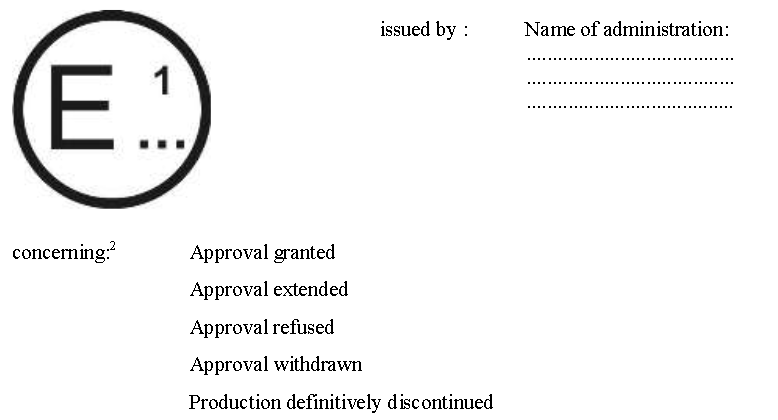
| 4.1.4. | Notice of approval or of extension or refusal or withdrawal of approval or production definitely discontinued of a type of device pursuant to this Regulation shall be communicated to the Parties to the 1958 Agreement which apply this Regulation, by means of a form conforming to the model in Annex 2 to this Regulation. | a0c0 |
| 4.1.5. | Every device conforming to a type approved under this Regulation shall bear in the space referred to in paragraph 3.3. above, and in addition to the markings prescribed in paragraphs 3.1. and 3.2. or 3.4. above respectively, an approval mark as described in paragraphs 4.2. and 4.3. below. | a0c0 |
| 4.2. | Composition of the approval mark | a0c0 |
| ... | The approval mark shall consist of: | a0c0 |
| 4.2.1. | An international approval marking, comprising: | a0c0 |
| 4.2.1.1. | A circle surrounding the letter "E" followed by the distinguishing number of the country which has granted approval; [2] | a0c0 |
|
|
|
a0c0 |
| 4.2.1.2. | The approval number prescribed in paragraph 4.1.3. above. | a0c0 |
| 4.2.2. | The following additional symbol (or symbols): | a0c0 |
| 4.2.2.1. | One or more of the numbers: 1, 1a, 1b, 2a, 2b, 5 or 6, according to whether the device belongs to one or more categories 1, 1a, 1b, 2a, 2b, 5 or 6 for which approval is sought in accordance with paragraph 2.1. above; | a0c0 |
| 4.2.2.2. | On devices which cannot be mounted on either side of the vehicle indiscriminately, a horizontal arrow showing in which position the device is to be mounted (the arrow shall be directed outwards from the vehicle in the case of devices of categories 1, 1a, 1b, 2a and 2b and towards the front of the vehicle in the case of devices of categories 3, 4, 5 and 6). In addition, for devices of category 6 an indication "R" or "L" shall in this case be shown on the device, indicating the right or left side of the vehicle. | a0c0 |
| 4.2.2.3. | To the right side of the symbol mentioned in paragraph 4.2.2.1. above; it shall be marked on each device: | a0c0 |
| ... | (a) The additional letter "D", on devices which may be used as part of an assembly of two lamps. | a0c0 |
| ... | (b) The additional letter "Y", on devices which may be used as part of an interdependent lamps system. | a0c0 |
| 4.2.2.4. | On devices with reduced light distribution in conformity to paragraph 2.1.3. of Annex 4 to this Regulation a vertical arrow starting from a horizontal segment and directed downwards. | a0c0 |
| 4.2.2.5. | The two digits of the approval number which indicate the series of amendments in force at the time of issue of the approval and, if necessary, the required arrow may be marked close to the above additional symbols; | a0c0 |
| 4.2.2.6. | The marks and symbols referred to in paragraphs 4.2.1. and 4.2.2. above shall be clearly legible and be indelible even when the device is fitted in the vehicle. | a0c0 |
| 4.3. | Arrangement of the approval mark | a0c0 |
| 4.3.1. | Independent lamps | a0c0 |
| ... | Annex 3, Figure 1, to this Regulation gives an example of arrangement of the approval mark with the above-mentioned additional symbols. | a0c0 |
| ... | If different types of lamps complying with the requirements of several Regulations, use the same outer lens having the same or different colour, a single international approval mark may be affixed, consisting of a circle surrounding the letter "E" followed by the distinguishing number of the country which has granted the approval, and an approval number. This approval mark may be located anywhere on the lamp, provided that: | a0c0 |
| 4.3.1.1. | It is visible after their installation. | a0c0 |
| 4.3.1.2. | The identification symbol for each lamp appropriate to each Regulation under which approval has been granted, together with the corresponding series of amendments incorporating the most recent major technical amendments to the Regulation at the time of issue of the approval and if necessary, the required arrow shall be marked. | a0c0 |
| 4.3.1.3. | The size of the components of a single approval mark shall not be less than the minimum size required for the smallest of the individual marks under which approval has been granted. | a0c0 |
| 4.3.1.4. |
The main body of the lamp shall include the space described in paragraph 3.3. above and shall bear the approval mark of the actual function(s). |
a0c0 |
| 4.3.1.5. | Figure 4 in Annex 3 to this Regulation gives examples of an approval mark with the above-mentioned additional symbols. | a0c0 |
| 4.3.2. | Grouped, combined or reciprocally incorporated lamps | a0c0 |
| 4.3.2.1. | Where grouped, combined or reciprocally incorporated lamps have been found to comply with the requirements of several Regulations, a single international approval mark may be applied consisting of a circle surrounding the letter "E" followed by the distinguishing number of the country which has granted the approval, and an approval number. This approval mark may be located anywhere on the grouped, combined or reciprocally incorporated lamps, provided that: | a0c0 |
| 4.3.2.1.1. | It is visible after the installation of the lamps; | a0c0 |
| 4.3.2.1.2. | No part of the grouped, combined or reciprocally incorporated lamps that transmits light can be removed without at the same time removing the approval mark. | a0c0 |
| 4.3.2.2. | An identification symbol for each lamp appropriate to each Regulation under which approval has been granted, together with the corresponding series of amendments incorporating the most recent major technical amendments to the Regulation at the time of issue of the approval and, if necessary, the required arrow shall be marked: | a0c0 |
| 4.3.2.2.1. | Either on the appropriate light-emitting surface; | a0c0 |
| 4.3.2.2.2. | Or in a group, in such a way that each lamp of the grouped, combined or reciprocally incorporated lamps may be clearly identified. | a0c0 |
| 4.3.2.3. | The size of the components of a single approval mark shall not be less than the minimum size required for the smallest of the individual marks by the Regulation under which approval has been granted. | a0c0 |
| 4.3.2.4. | An approval number shall be assigned to each type approved. The same Contracting Party may not assign the same number to another type of grouped, combined or reciprocally incorporated lamps covered by this Regulation. | a0c0 |
| 4.3.2.5. | Annex 3, Figure 2, to this Regulation gives examples of the arrangement of the approval marks for grouped, combined or reciprocally incorporated lamps with all the above-mentioned additional symbols. | a0c0 |
| 4.3.3. | Lamps reciprocally incorporated with other lamps, of which the lens may also be used for other types of headlamps. | a0c0 |
| ... | The provisions laid down in paragraph 4.3.2. above are applicable. | a0c0 |
| 4.3.3.1. | In addition, where the same lens is used, the latter may bear the different approval marks relating to the different types of headlamps or units of lamps, provided that the main body of the headlamp, even if it cannot be separated from the lens, also comprises the space described in paragraph 3.3. above and bears the approval marks of the actual functions. | a0c0 |
| ... | If different types of headlamps comprise the same main body, the latter may bear the different approval marks. | a0c0 |
| 4.3.3.2. | Annex 3, Figure 3, to this Regulation gives examples of approval marks for lamps reciprocally incorporated with a headlamp. | a0c0 |
| 4.4. | The approval marking shall be clearly legible and indelible. It may be placed on an inner or outer part (transparent or not) of the device which cannot be separated from the transparent part of the device emitting the light. In any case the marking shall be visible when the device is fitted on the vehicle or when a movable part such as the hood or boot lid or a door is opened. | a0c0 |
| 5. |
|
a0c0 |
| ... |
The requirements pertinent to each lamp and to the category/ies of vehicle on which the lamp is intended to be installed shall be applied, where its verification at the moment of lamp type approval is feasible. |
a2c0 |
| 5.1. | Each device supplied shall conform to the specifications set forth in paragraphs 6. and 8. below. | a0c0 |
| 5.2. | The devices shall be so designed and constructed that under normal conditions of use and notwithstanding the vibrations to which they may be subjected in such use, their satisfactory operation remains assured and they retain the characteristics prescribed by this Regulation. | a0c0 |
| 5.3. | In the case of light source modules, it shall be checked that: | a0c0 |
| 5.3.1. | The design of the light source module(s) shall be such as: | a0c0 |
| ... | (a) That each light source module can only be fitted in no other position than the designated and correct one and can only be removed with the use of tool(s); | a0c0 |
| ... | (b) If there are more than one light source module used in the housing for a device, light source modules having different characteristics can not be interchanged within the same lamp housing. | a0c0 |
| 5.3.2. | The light source module(s) shall be tamperproof. | a0c0 |
| 5.3.3. | A light source module shall be so designed that regardless of the use of tool(s), it shall not be mechanically interchangeable with any replaceable approved light source. | a0c0 |
| 5.4. |
In case of failure of the variable intensity control of a direction indicator of category 2b emitting more than the maximum value of category 2a, requirements of steady luminous intensity of category 2a shall be fulfilled automatically. |
a0c0 |
| 5.5. | In the case of replaceable light source(s): | a0c0 |
| 5.5.1. |
|
a3c0 |
| 5.5.2. | The design of the device shall be such that light source cannot be fixed in any other position but the correct one. | a0c0 |
| 5.5.3. |
The light source holder shall conform to the characteristics given in IEC Publication 60061. The holder data sheet relevant to the category of light source used, applies. |
a0c0 |
|
|
|
a2c0 |
| 5.6. | For direction indicator lamps of categories 1, 1a, 1b, 2a or 2b the flash may be produced by sequential activation of their light sources if the following conditions are met: | a0c0 |
| ... | (a) Each light source, after its activation, shall remain lit until the end of the ON cycle; | a0c0 |
| ... |
(b) The sequence of activation of the light sources shall |
a3c0 |
| ... |
(c) |
a3c0 |
| ... | (d) The variation shall finish no more than 200 ms after the beginning of the ON cycle; | a0c0 |
| ... |
(e) The orthogonal projection of the |
a3c0 |
| ... | Compliance to the conditions mentioned above shall be verified in flashing mode. | a0c0 |
| 5.7. | An interdependent lamp system shall meet the requirements when all its interdependent lamps are operated together. | a0c0 |
| ... | However, if the interdependent lamp system providing the rear direction indicator function is partly mounted on the fixed component and partly mounted on a movable component, the interdependent lamp(s) specified by the Applicant shall meet the geometric visibility, colorimetric and photometric requirement, at all fixed positions of the movable component(s). This does not apply to interdependent direction indicator lamp(s) intended for fitting on vehicle(s) where, to fulfil or complete the geometric visibility angle, additional lamps are activated when the movable component is in any fixed open position, provided that these additional lamps satisfy all the position, photometric and colorimetric requirements applicable to the direction indicator lamps installed on the movable component. | a0c0 |
| 6. |
|
a0c0 |
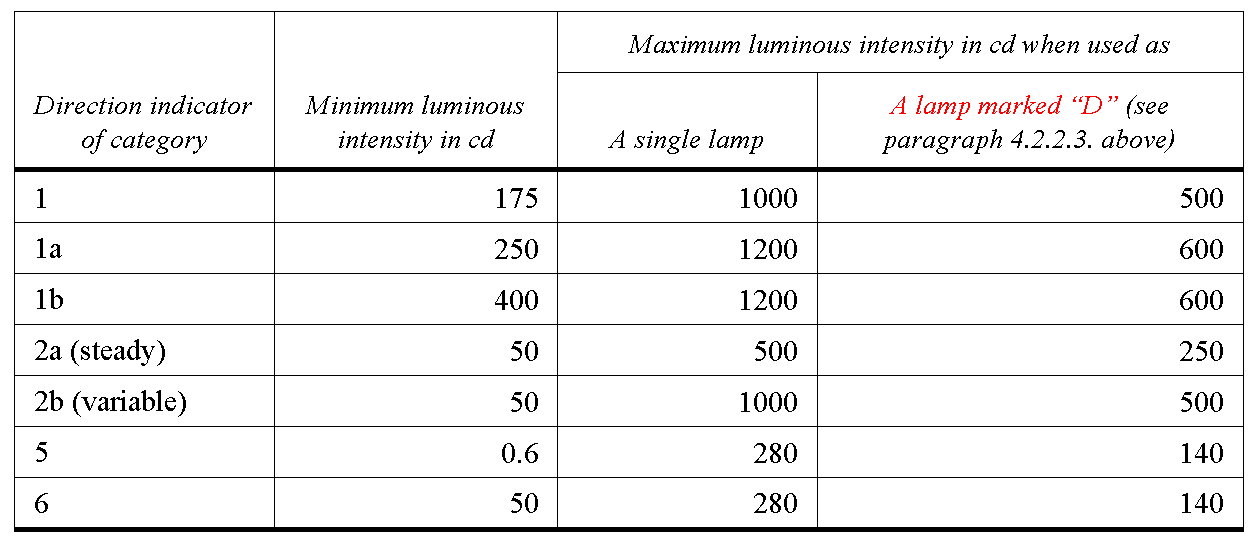
| 6.1. | The light emitted by each of the two devices supplied shall be in the case of direction indicators of categories 1, 1a, 1b, 2a, 2b, in the reference axes, in the case of direction indicators of categories 5 or 6 in direction A according to Annex 1 of not less than the minimum intensity and of not more than the maximum intensity specified below: | a2c0 |
| ... |
|
a2c0 |
| 6.1.1. | For an assembly of two or more direction indicator lamps the total intensity shall not exceed the maximum value. | a0c0 |
| 6.1.2. | When an assembly of two lamps marked "D" having the same function is deemed to be a single lamp, it shall comply with the requirements for: | a0c0 |
| ... | (a) Maximum intensity if all lamps together are lit; | a0c0 |
| ... | (b) Minimum intensity if one lamp has failed. | a0c0 |
| 6.2. | In case of failure of a single lamp, or of an interdependent lamp system of the categories 1, 1a, 1b, 2a and 2b, containing more than one light source the following provisions shall apply: | a0c0 |
| 6.2.1. | A group of light sources, wired so that the failure of any one of them causes all of them to stop emitting light, shall be considered to be one light source. | a0c0 |
| 6.2.2. |
A signal for activation of the tell-tale prescribed in paragraph 6.5.8. of Regulation No. 48 shall be produced if: |
a0c0 |
| ... | (a)Any one light source has failed, or | a0c0 |
| ... |
(b)In the case of a lamp designed for only two |
a1c0 |
| ... |
(c)As a consequence of a failure of one or more light sources, the intensity in one of the following directions as indicated in Annex 4 to this Regulation is less than the minimum intensity required: |
a0c0 |
| ... |
(i)H=0°, V=0° |
a0c0 |
| ... |
(ii)H=20° to the outside of the vehicle, V= +5° |
a0c0 |
| ... |
(iii)H=10° to the inside of the vehicle, V= 0°. |
a0c0 |
| 6.3. | Outside the reference axis, within the angular fields specified in the arrangement diagrams in Annex 1 to this Regulation, the intensity of the light emitted by each of the two devices supplied shall: | a0c0 |
| 6.3.1. | In each direction corresponding to the points in the relevant table of luminous-intensity distribution reproduced in Annex 4 to this Regulation, be not less than the minimum specified in paragraph 6.1. above multiplied by the percentage specified in the said table for the direction in question; | a0c0 |
| 6.3.1.1. | In divergence from paragraphs 6.3. and 6.3.1. above, for categories 5 direction indicators, to the rear, a minimum value of 0.6 cd is required throughout the fields specified in Annex 1; | a0c0 |
| 6.3.2. | In no direction within the area from which the indicator lamp is visible, exceed the maximum specified in paragraph 6.1. above; | a0c0 |
| 6.3.3. | Moreover, | a0c0 |
| 6.3.3.1. | Throughout the fields defined in the diagrams in Annex 1, the intensity of the light emitted shall be not less than 0.7 cd for devices of category 1b, not less than 0.3 cd for devices of categories 1, 1a, 2a and for those of category 2b by day; it shall not be less than 0.07 cd for devices of category 2b by night; | a0c0 |
| 6.3.3.2. | The provisions of paragraph 2.2. of Annex 4 to this Regulation on local variations of intensity shall be observed. | a0c0 |
| 6.4. | In general the intensities shall be measured with the light source(s) continuously alight. | a0c0 |
| ... | However, depending on the construction of the device, for example, the use of light-emitting diodes (LED), or the need to take precautions to avoid overheating, it is allowed to measure the lamps in flashing mode. | a0c0 |
| ... |
This shall be achieved by switching with a frequency of f = 1.5 ± 0.5Hz with the pulse width greater than 0.3s, measured at 95 per cent peak light intensity. |
a0c0 |
| ... | In the case of replaceable filament lamps, the filament lamps shall be operated at reference luminous flux during on time. | a0c0 |
| ... |
In the case of LED light sources all measurements shall be made at 6.75 V, 13.5 V or 28.0 V; the luminous flux value produced during on time shall be corrected. The correction factor is the ratio between the objective luminous flux and the value of the luminous flux during on time found at the voltage applied. |
a0c0 |
| ... | In all other cases the voltage as required in paragraph 7.1.1. below shall be switched with a rise time and fall time shorter than 0.01 s; no overshoot is allowed. | a0c0 |
| ... | In the case of measurements taken in flashing mode the reported luminous intensity shall be represented by the maximum intensity. | a0c0 |
| 6.5. |
In the case of devices of category 2b the time that elapses between energizing the light source(s) and the light output measured on the reference axis to reach 90 per cent of the value measured in accordance with paragraph 6.3. above shall be measured for the extreme levels of luminous intensity produced by the direction indicator. The time measured to obtain the lowest luminous intensity shall not exceed the time measured to obtain the highest luminous intensity. |
a0c0 |
| 6.6. | The variable intensity control shall not generate signals which cause luminous intensities: | a0c0 |
| 6.6.1. | Outside the range specified in paragraph 6.1. above and | a0c0 |
| 6.6.2. | Exceeding the category 2a maximum specified in paragraph 6.1. above: | a0c0 |
| ... | (a) For systems depending only on daytime and night time conditions: under night time conditions; | a0c0 |
| ... | (b) For other systems: under reference conditions as demonstrated by the manufacturer. [1] | a0c0 |
|
|
Good visibility (meteorological optical range MOR > 2,000m defined according to WMO, Guide to Meteorological Instruments and Methods of Observation, Sixth Edition, ISBN: 92-63-16008-2, pp 1.9.1/1.9.11, Geneva 1996 ) and clean lens. |
a0c0 |
| 6.7. | Annex 4, referred to in paragraph 6.3.1. above, gives particulars of the measurement methods to be used. | a0c0 |
| 7. |
|
a0c0 |
| 7.1. | All measurements, photometric and colorimetric, shall be made: | a0c0 |
| 7.1.1. | In the case of a lamp with replaceable light source, if not supplied by an electronic light source control gear or a variable intensity control, with an uncoloured or coloured standard light source of the category prescribed for the device; supplied with the voltage: | a0c0 |
| ... | (a) In the case of filament lamp(s), it is necessary to produce the reference luminous flux required for that category of filament lamp; | a0c0 |
| ... |
(b) In the case of LED light source(s) of 6.75 V, 13.5 V or 28.0 V; the luminous flux value produced shall be corrected. The correction factor is the ratio between the objective luminous flux and the mean value of the luminous flux found at the voltage applied. |
a0c0 |
| 7.1.2. | In the case of a lamp equipped with non-replaceable light sources (filament lamps and other), at 6.75 V, 13.5 V or 28.0 V respectively. | a0c0 |
| 7.1.3. |
In the case of a system that uses an electronic light source control gear or a variable intensity control, being part of the lamp[2] applying at the input terminals of the lamp the voltage declared by the manufacturer or, if not indicated, 6.75V, 13.5V or 28.0V respectively. |
a0c0 |
|
|
|
a0c0 |
| 7.1.4. | In the case of a system that uses an electronic light source control gear or a variable intensity control, not being part of the lamp with the voltage declared by the manufacturer applied to the input terminals of the lamp. | a0c0 |
| 7.2. |
However in the case of a direction indicator of category 2b operated by a variable intensity control to obtain variable luminous intensity, photometric measurements shall be performed according to the applicant's description. |
a0c0 |
| 7.3. | The test laboratory shall require from the manufacturer the light source control gear or a variable intensity control needed to supply the light source and the applicable functions. | a0c0 |
| 7.4. |
The voltage to be applied to the lamp shall be noted in the communication form in Annex 2 of this Regulation. |
a0c0 |
| 7.5. | The limits of the apparent surface in the direction of the reference axis of a direction indicator shall be determined. However, in the case of category 5 and 6 direction indicators, the limits of the light emitting surface shall be determined. | a0c0 |
| 8. |
|
a0c0 |
| ... | The colour of the light emitted inside the field of the light distribution grid defined in paragraph 2. of Annex 4 shall be amber. Outside this field, no sharp variation of colour shall be observed. To check these colorimetric characteristics, the test procedure described in paragraph 7. of this Regulation shall be applied. These requirements shall also apply within the range of variable luminous intensity produced by direction indicators of category 2b. | a0c0 |
| ... | However, for lamps equipped with non-replaceable light sources (filament lamps and other), the colorimetric characteristics should be verified with the light sources present in the lamp, in accordance with relevant subparagraphs of paragraph 7.1. of this Regulation. | a0c0 |
| 9. |
|
a0c0 |
| 9.1. | Every modification of a type of direction indicator shall be notified to the Type Approval Authority which approved the type. The Type Approval Authority may then either: | a0c0 |
| 9.1.1. | Consider that the modifications made are unlikely to have an appreciable adverse effect and that in any case the device still complies with the requirements; or | a0c0 |
| 9.1.2. | Require a further test report from the Technical Service responsible for conducting the tests. | a0c0 |
| 9.2. | Confirmation or refusal of approval, specifying the alterations, shall be communicated by the procedure specified in paragraph 4.1.4. above to the Parties to the Agreement applying this Regulation. | a0c0 |
| 9.3. |
The Type Approval Authority issuing the extension of approval shall assign a series number for such an extension and inform thereof the other Parties to the 1958 Agreement applying this Regulation by means of a communication form conforming to the model in Annex 2 to this Regulation. |
a0c0 |
| 10. |
|
a0c0 |
| ... | The conformity of production procedures shall comply with those set out in the Agreement, Appendix 2 (E/ECE/324-E/ECE/TRANS/505/Rev.2), with the following requirements: | a0c0 |
| 10.1. |
The compliance with the requirements set forth in paragraphs 6. and 8. above shall be verified as follows: |
a2c0 |
|
|
The minimum requirements for conformity of production control procedures set forth in Annex 5 to this Regulation shall be complied with. | a2c0 |
|
|
The minimum requirements for sampling by an inspector set forth in Annex 6 to this Regulation shall be complied with. |
a2c0 |
|
|
|
a2c0 |
|
|
The Type Approval Authority which has granted type approval may at any time verify the conformity control methods applied in each production facility. The normal frequency of these verifications shall be once every two years. | a2c0 |
| 11. |
|
a0c0 |
| 11.1. | The approval granted in respect of a device pursuant to this Regulation may be withdrawn if the foregoing requirements are not met. | a0c0 |
| 11.2. | If a Contracting Party to the Agreement which applies this Regulation withdraws an approval it has previously granted, it shall forthwith so notify the other Contracting Parties applying this Regulation, by means of a communication form conforming to the model in Annex 2 to this Regulation. | a0c0 |
| 12. |
|
a0c0 |
| ... | If the holder of the approval completely ceases to manufacture a device approved in accordance with this Regulation, he shall so inform the Type Approval Authority which granted the approval. Upon receiving the relevant communication, that Authority shall inform thereof the other Parties to the 1958 Agreement applying this Regulation by means of a communication form conforming to the model in Annex 2 to this Regulation. | a0c0 |
| 13. |
|
a0c0 |
| ... | The Contracting Parties to the 1958 Agreement which apply this Regulation shall communicate to the United Nations Secretariat the names and addresses of the Technical Services responsible for conducting approval tests and of the | a0c0 |
| 14. |
|
a0c0 |
|
|
|
a5c0 |
|
|
|
a5c0 |
|
|
|
a5c0 |
|
|
|
a5c0 |
|
|
|
a5c0 |
|
|
|
a5c0 |
|
|
|
a5c0 |
|
|
|
a5c0 |
|
|
|
a5c0 |
|
|
|
a5c0 |
|
|
|
a5c0 |
|
|
|
a5c0 |
|
|
|
a5c0 |
|
|
|
a5c0 |
|
|
|
a5c0 |
|
|
|
a5c0 |
|
|
|
a5c0 |
|
|
|
a5c0 |
|
|
|
a5c0 |
|
|
|
a5c0 |
|
|
|
a5c0 |
| A1 |
|
a0c0 |
| A1 |
|
a0c0 |
|
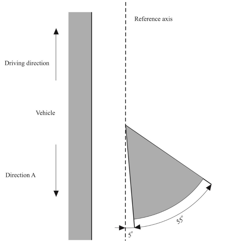
A1 |
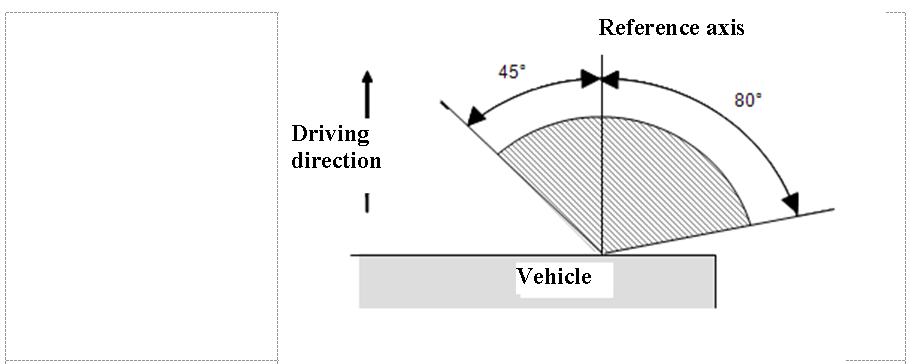
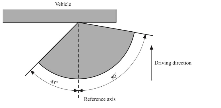
The angles shown in these arrangements are correct for devices to be mounted on the right side of the vehicle. The arrows in these diagrams point towards the front of the vehicle. |
a0c0 |
| A1 |
In all cases, the minimum vertical angles of light distribution in space of direction indicator lamps are 15° above and 15° below the horizontal except: |
a0c0 |
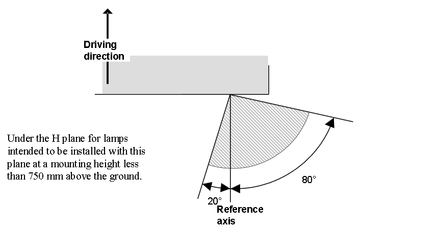
| A1 |
(a) Direction indicator lamps intended to be installed with the H plane of the lamp at a mounting height of less than 750 mm above the ground, for which they are 15° above and 5° below the horizontal; |
a0c0 |
| A1 |
(b) Optional direction indicator lamps intended to be installed with the H plane of the lamp at a mounting height of more than 2100 mm above the ground, for which they are 5° above and 15° below the horizontal; |
a0c0 |
| A1 |
(c) Direction indicator lamps of Category 6, for which they are 30° above and 5° below the horizontal. |
a0c0 |
| A1 | Minimum horizontal visibility angles | a0c0 |
| A1 | Direction indicators for the front of the vehicle | a0c0 |
| A1 | Category 1: For use at a distance not less than 40 mm from the dipped-beam headlamp and/or the front fog lamp; | a0c0 |
| A1 | Category 1a: For use at a distance greater than 20 mm but less than 40 mm from the dipped-beam headlamp and/or the front fog lamp; | a0c0 |
| A1 | Category 1b: For use at a distance less than or equal to 20 mm from the dipped-beam headlamp and/or the front fog lamp. | a0c0 |
| A1 |
|
a2c0 |
| A1 |

|
a2c0 |
| A1 | Categories 2a and 2b: Direction indicators for the rear of the vehicle | a0c0 |
| A1 | Category 2a: Rear direction indicator lamps with steady luminous intensity | a0c0 |
| A1 | Category 2b: Rear direction indicator lamps with variable luminous intensity | a0c0 |
| A1 |
|
a0c0 |
| A1 |
|
a0c0 |
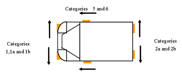
| A1 | Categories 5 and 6: Supplementary side direction indicators for use on a vehicle also equipped with categories 1, 1a or 1b and 2a or 2b direction indicators | a0c0 |
| A1 |
|
a0c0 |
| A2 |
|
a0c0 |
| A2 |
|
a0c0 |
| A2 | (Maximum format: A4 (210 x 297 mm)) | a0c0 |
| A2 |
|
a0c0 |
| A2 | of a type of direction indicator pursuant to Regulation No. 6 | a0c0 |
| A2 | Approval No........... Extension No........... | a0c0 |
| A2 1. | Trade name or mark of the device | a0c0 |
| A2 2. | Manufacturer's name for the type of device: | a0c0 |
| A2 3. | Manufacturer's name and address: | a0c0 |
| A2 4. | If applicable, name and address of the manufacturer's representative: | a0c0 |
| A2 5. | Submitted for approval on: | a0c0 |
| A2 6. | Technical Service responsible for conducting approval tests: | a0c0 |
| A2 7. | Date of test report issued by that Service: | a0c0 |
| A2 8. | Number of test report issued by that Service: | a0c0 |
| A2 9. | Concise description: | a0c0 |
| A2 | Category: 1, 1a, 1b, 2a, 2b, 5, 6[2] | a0c0 |
| A2 | Number, category: | a0c0 |
| A2 | Function(s) produced by an interdependent lamp forming part of an interdependent lamps system: | a0c0 |
| A2 | Voltage and wattage: | a0c0 |
| A2 | Light source module specific identification code: | a0c0 |
| A2 |
Only for limited mounting height of equal to or less than 750 mm above the ground: yes/no[2] |
a0c0 |
| A2 | Geometrical conditions of installation and relating variations, if any: | a0c0 |
| A2 | Application of an electronic light source control gear/variable intensity control: | a0c0 |
| A2 | (a) Being part of the lamp: yes/no[2] | a0c0 |
| A2 | (b) Being not part of the lamp: yes/no[2] | a0c0 |
| A2 | Input voltage(s) supplied by an electronic light source control gear/variable intensity control: | a0c0 |
| A2 | Electronic light source control gear/variable intensity control manufacturer and identification number (when the light source control gear is part of the lamp but is not included into the lamp body): | a0c0 |
| A2 | Variable luminous intensity: yes/no[2] | a0c0 |
| A2 | Sequential activation of light sources (see paragraph 5.6. of this Regulation): yes/no[2] | a0c0 |
| A2 10. | Position of the approval mark: | a0c0 |
| A2 11. | Reason(s) for extension (if applicable): | a0c0 |
| A2 12. | Approval granted/extended/refused/withdrawn:[2] | a0c0 |
| A2 13. | Place: | a0c0 |
| A2 14. | Date: | a0c0 |
| A2 15. | Signature: | a0c0 |
| A2 16. | The list of documents deposited with the Type Approval Authority which has granted approval is annexed to this communication and may be obtained on request | a0c0 |
|
A2 |
|
a0c0 |
| A3 |
|
a0c0 |
| A3 |
|
a0c0 |
| A3 |
|
a0c0 |
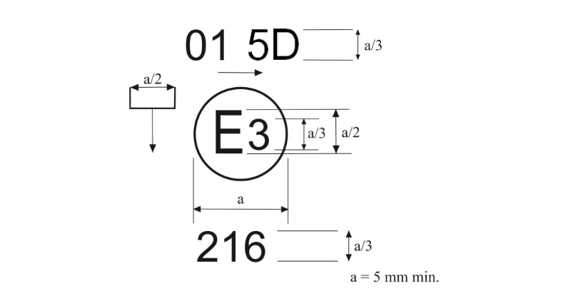
| A3 | The device bearing the approval marking shown above is a category-5 device (side direction indicator) approved in Italy (E 3) under No. 216, which may also be used in an assembly of two lamps. The horizontal arrow shows in what position this device, which cannot be mounted on either side of the vehicle indiscriminately, is to be mounted. The arrow points towards the front of the vehicle. The vertical arrow starting from a horizontal segment and directed downwards indicates a permissible mounting height of equal to or less than 750 mm from the ground for this device. | a0c0 |
| A3 | The number mentioned close to the symbol "5D" indicates that the approval was granted according to the requirements of Regulation No. 6 as amended by the 01 series of amendments. | a0c0 |
| A3 | The direction in which the arrows on the approval mark point, according to the category of the device, is shown below: | a0c0 |
| A3 |
|
a0c0 |
| A3 | Note:The approval number and the additional symbols shall be placed close to the circle and either above or below the letter "E", or to the right or left of that letter. The digits of the approval number shall be on the same side of the letter "E" and face the same direction. The use of Roman numerals as approval numbers should be avoided so as to prevent any confusion with other symbols. | a0c0 |
| A3 |
|
a0c0 |
| A3 | Figure 2 | a0c0 |
| A3 | The vertical and horizontal lines schematize the shape of the light-signaling device. These are not part of the approval mark. | a0c0 |
| A3 |

|
a0c0 |
| A3 | Note: The three examples of approval marks shown above (models A, B and C) represent three possible variables for the marking of a lighting device when two or more lamps are part of the same assembly of grouped, combined or reciprocally incorporated lamps. | a0c0 |
| A3 |
They indicate that the device was approved in the Netherlands (E 4) under number 3333 and comprise: |
a0c0 |
| A3 |
A rear direction indicator lamp with variable luminous intensity (category 2b) approved in accordance with the 01 series of amendments to Regulation No. 6; |
a0c0 |
| A3 |
A red rear position (side) lamp with variable luminous intensity (R2) approved in accordance with the 02 series of amendments to Regulation No. 7; |
a0c0 |
| A3 |
A rear fog lamp with variable luminous intensity (F2) approved in accordance with Regulation No.38 in its original version; |
a0c0 |
| A3 |
A reversing lamp (AR) approved in accordance with Regulation No. 23 in its original version; |
a0c0 |
| A3 |
A stop-lamp with variable luminous intensity (S2) approved in accordance with the 02 series of amendments to Regulation No. 7. |
a0c0 |
| A3 |
|
a0c0 |
| A3 | Note: The three examples shown above correspond to a lighting device bearing an approval mark relating to: | a0c0 |
| A3 |
A front position lamp approved in accordance with the 01 series of amendments to Regulation No. 7; |
a0c0 |
| A3 | A headlamp with a passing beam designed for right-hand and left-hand traffic and a driving beam with a maximum intensity comprised between 86,250 and 101,250 candelas, approved in accordance with the 02 series of amendments to Regulation No. 20; | a0c0 |
| A3 |
A front fog lamp approved in accordance with the 02 series of amendments to Regulation No. 19; |
a0c0 |
| A3 | A front direction indicator lamp of category 1a approved in accordance with the 01 series of amendments to Regulation No. 6. | a0c0 |
| A3 |
|
a0c0 |
| A3 | Figure 3 | a0c0 |
| A3 |

|
a0c0 |
| A3 | The above example corresponds to the marking of a lens intended to be used in different types of headlamps, namely: | a0c0 |
| A3 |
Either: A headlamp with a passing beam designed for right-hand and left-hand traffic and a driving beam with a maximum intensity comprised between 86,250 and 101,250 candelas, approved in Germany (E 1) in accordance with the requirements of Regulation No. 8 as amended by the 04 series of amendments; which is reciprocally incorporated with a front direction indicator approved in accordance with the 01 series of amendments to Regulation No. 6; |
a0c0 |
| A3 | Or: A headlamp with a passing beam designed for right-hand and left-hand traffic and a driving beam, approved in Germany (E 1) in accordance with the requirements of Regulation No. 1 as amended by the 01 series of amendments, which is reciprocally incorporated with the same front direction indicator as above; | a0c0 |
| A3 | Or even: Either of the above-mentioned headlamps approved as a single lamp. | a0c0 |
| A3 | The main body of the headlamp shall bear the only valid approval number, for instance: | a0c0 |
| A3 |
|
a0c0 |
| A3 |
|
a0c0 |
| A3 | Figure 4 | a0c0 |
| A3 |

|
a0c0 |
| A3 |
The above example corresponds to the marking of a lens intended to be used in different types of lamps. The approval marks indicate that the device was approved in Spain (E9) under approval number 1432 and comprises: |
a0c0 |
| A3 |
A rear fog lamp (F) approved in accordance with Regulation No. 38 in its original version; |
a0c0 |
| A3 |
A rear direction indicator lamp of category 2a approved in accordance with the 01 series of amendments to Regulation No. 6; |
a0c0 |
| A3 |
A reversing lamp (AR) approved in accordance with Regulation No. 23 in its original version; |
a0c0 |
| A3 |
A red rear position (side) lamp (R) approved in accordance with the 02 series of amendments to Regulation No. 7; |
a0c0 |
| A3 |
A stop-lamp with one level of illumination (S1) approved in accordance with the 02 series of amendments to Regulation No. 7. |
a0c0 |
| A3 | Light source modules | a0c0 |
| A3 | MD E3 17325 | a0c0 |
| A3 | The light source module bearing the identification code shown above has been approved together with a lamp approved in Italy (E3) under approval number 17325. | a0c0 |
| A3 |
|
a0c0 |
| A3 |

|
a0c0 |
| A3 | Marking of an interdependent lamp comprising part of an interdependent lamp system providing: | a0c0 |
| A3 | A rear direction indicator lamp (category 2a) approved in accordance with the 01 series of amendments to Regulation No. 6. This is also marked Y as it is an interdependent lamp forming part of an interdependent lamp system, | a0c0 |
| A3 | A rear fog lamp with variable luminous intensity (F2) approved in accordance with Regulation No. 38 in its original version. | a0c0 |
| A3 |

|
a0c0 |
| A3 | Marking of an interdependent lamp comprising | a0c0 |
| A3 | part of an interdependent lamp system providing: | a0c0 |
| A3 | A rear direction indicator lamp (category 2a) approved in accordance with the 01 series of amendments to Regulation No. 6. This is also marked Y as it is an interdependent lamp forming part of an interdependent lamp system, | a0c0 |
| A3 |
A red rear position (side) lamp (R1) approved in accordance with the 02 series of amendments to Regulation No. 7, |
a0c0 |
| A3 | A stop lamp (S1) approved in accordance with Regulation No. 7 in its original version. | a0c0 |
| A4 |
|
a0c0 |
| A4 |
|
a0c0 |
| A4 1. | Measurement methods | a0c0 |
| A4 1.1. | During photometric measurements, stray reflections shall be avoided by appropriate masking. | a0c0 |
| A4 1.2. | In case the results of measurements should be challenged, measurements shall be carried out in such a way as to meet the following requirements: | a0c0 |
| A4 1.2.1. | The distance of measurement shall be such that the law of the inverse of the square of the distance is applicable; | a0c0 |
| A4 1.2.2. |
The measuring equipment shall be such that the angular aperture of the receiver viewed from the reference centre of the light is comprised between 10' and 1 degree; |
a0c0 |
| A4 1.2.3. | The intensity requirement for a particular direction of observation shall be deemed to be satisfied if that requirement is met in a direction deviating by not more than one-quarter of a degree from the direction of observation. | a0c0 |
| A4 1.3. | In the case where the device may be installed on the vehicle in more than one or in a field of different positions the photometric measurements shall be repeated for each position or for the extreme positions of the field of the reference axis specified by the manufacturer. | a0c0 |
| A4 2. | Table of standard light distribution in space for direction indicator lamps of categories 1, 1a, 1b, 2a, 2b. | a0c0 |
| A4 |
|
a0c0 |
| A4 | For direction indicators of category 6 | a0c0 |
| A4 |
|
a0c0 |
| A4 2.1. |
The direction H = 0° and V = 0° corresponds to the reference axis. (On the vehicle, it is horizontal, parallel to the median longitudinal plane of the vehicle and oriented in the required direction of visibility.) It passes through the centre of reference. The values shown in the tables give, for the various directions of measurement, the minimum intensities as a percentage of the minimum intensities required in the table in paragraph 6.1. of this Regulation: |
a0c0 |
| A4 2.1.1. |
In the direction H = 0° and V = 0° for categories 1, 1a, 1b, 2a, 2b and in the case of category 5 in the angular area in the direction A as prescribed in Annex 1; |
a0c0 |
| A4 2.1.2. |
In the direction H = 5° and V = 0° for category 6. |
a0c0 |
| A4 2.1.3. |
However, in the case where a device is intended to be installed with its H plane at a mounting height less than 750 mm above the ground, the photometric intensity is verified only up to an angle of 5° downwards. |
a0c0 |
| A4 2.2. | Within the field of light distribution of paragraph 2. above, schematically shown as a grid, the light pattern should be substantially uniform, i.e. in so far as the light intensity in each direction of a part of the field formed by the grid lines shall meet at least the lowest minimum value being shown on the grid lines surrounding the questioned direction as a percentage. | a0c0 |
| A4 3. | Photometric measurement of lamps | a0c0 |
| A4 | The photometric performance shall be checked: | a0c0 |
| A4 3.1. | For non-replaceable light sources (filament lamps and other): | a0c0 |
| A4 |
With the light sources present in the lamp, in accordance with the relevant sub-paragraph of paragraph 7.1. of this Regulation. |
a0c0 |
| A4 3.2. | For replaceable light source(s): | a0c0 |
| A4 |
When equipped with light source(s) at 6.75V, 13.5V or 28.0V, the luminous intensity values produced shall be corrected. For filament lamps the correction factor is the ratio between the reference luminous flux and the mean value of the luminous flux found at the voltage applied (6.75V, 13.5V or 28.0V). |
a0c0 |
| A4 |
For LED light sources the correction factor is the ratio between the objective luminous flux and the mean value of the luminous flux found at the voltage applied (6.75V, 13.5V or 28.0V). |
a0c0 |
| A4 |
The actual luminous fluxes of light source used shall not deviate more than 5 per cent from the mean value. Alternatively and in case of filament lamps only, a standard filament lamp may be used in turn, in each of the individual positions, operated at its reference flux, the individual measurements in each position being added together. |
a0c0 |
| A4 3.3. | For any direction indicator lamp except those equipped with filament lamp(s), the luminous intensities measured after one minute and after 30 minutes of operation in flashing mode (f = 1.5 Hz, duty factor 50 per cent), shall comply with the minimum and maximum requirements. The luminous intensity distribution after one minute of operation can be calculated by applying at each test point the ratio of luminous intensity measured in HV after one minute and after 30 minutes of operation as above described. | a0c0 |
| A5 |
|
a0c0 |
| A5 |
|
a0c0 |
| A5 1. | General | a0c0 |
| A5 1.1. | The conformity requirements shall be considered satisfied from a mechanical and geometric standpoint, if the differences do not exceed inevitable manufacturing deviations within the requirements of this Regulation. | a0c0 |
| A5 1.2. |
With respect to photometric performances, the conformity of mass-produced lamps shall not be contested if, when testing |
a2c0 |
| A5 1.2.1. |
No measured value deviates unfavourably by more than 20 per cent from the values prescribed in this Regulation In the case of a direction indicator of category 5 and for the minimum values required throughout the fields specified in Annex 1 the respective maximum deviations of the measured values shall correspond to the values shown in the table below: |
a2c0 |
| A5 1.2.1. |

|
a2c0 |
| A5 1.2.2. |
In the case of a direction indicator equipped with a replaceable light source, if results of the test described above do not meet the requirements, tests shall be repeated using another standard |
a2c0 |
| A5 1.3. |
|
a2c0 |
|
A5 |
|
a2c0 |
|
A5 |
|
a2c0 |
|
A5 |
|
a2c0 |
| A5 2. | Minimum requirements for verification of conformity by the manufacturer | a0c0 |
| A5 | For each type of direction indicator the holder of the approval mark shall carry out at least the following tests, at appropriate intervals. The tests shall be carried out in accordance with the provisions of this Regulation. | a0c0 |
| A5 | If any sampling shows non-conformity with regard to the type of test concerned, further samples shall be taken and tested. The manufacturer shall take steps to ensure the conformity of the production concerned. | a0c0 |
| A5 2.1. | Nature of tests | a0c0 |
| A5 | Tests of conformity in this Regulation shall cover the photometric and colorimetric characteristics. | a0c0 |
| A5 2.2. | Methods used in tests | a0c0 |
| A5 2.2.1. | Tests shall generally be carried out in accordance with the methods set out in this Regulation. | a0c0 |
| A5 2.2.2. | In any test of conformity carried out by the manufacturer, equivalent methods may be used with the consent of the Type Approval Authority responsible for approval tests. The manufacturer is responsible for proving that the applied methods are equivalent to those laid down in this Regulation. | a0c0 |
| A5 2.2.3. | The application of paragraphs 2.2.1. and 2.2.2. above requires regular calibration of test apparatus and its correlation with measurements made by a Type Approval Authority. | a0c0 |
| A5 2.2.4. | In all cases the reference methods shall be those of this Regulation, particularly for the purpose of administrative verification and sampling. | a0c0 |
| A5 2.3. | Nature of sampling | a0c0 |
| A5 | Samples of direction indicators shall be selected at random from the production of a uniform batch. A uniform batch means a set of direction indicators of the same type, defined according to the production methods of the manufacturer. | a0c0 |
| A5 | The assessment shall in general cover series production from individual factories. However, a manufacturer may group together records concerning the same type from several factories, provided these operate under the same quality system and quality management. | a0c0 |
| A5 2.4. | Measured and recorded photometric characteristics | a0c0 |
| A5 |
The sampled lamp shall be subjected to photometric measurements for the minimum values at the points listed in Annex 4, and the required chromaticity coordinates. |
a0c0 |
| A5 2.5. | Criteria governing acceptability | a0c0 |
| A5 | The manufacturer is responsible for carrying out a statistical study of the test results and for defining, in agreement with the Type Approval Authority, criteria governing the acceptability of his products in order to meet the specifications laid down for verification of conformity of products in paragraph 10.1. of this Regulation. | a0c0 |
| A5 | The criteria governing the acceptability shall be such that, with a confidence level of 95 per cent, the minimum probability of passing a spot check in accordance with Annex 6 (first sampling) would be 0.95. | a0c0 |
| A6 |
|
a0c0 |
| A6 |
|
a0c0 |
| A6 1. | General | a0c0 |
| A6 1.1. | The conformity requirements shall be considered satisfied from a mechanical and a geometric standpoint, in accordance with the requirements of this Regulation, if any, if the differences do not exceed inevitable manufacturing deviations. | a0c0 |
| A6 1.2. |
With respect to photometric performance, the conformity of mass-produced lamps shall not be contested if, when testing |
a2c0 |
| A6 1.2.1. |
|
a2c0 |
| A6 1.2.2. | If, in the case of a direction indicator equipped with a replaceable light source and if results of the test described above do not meet the requirements, tests on direction indicators shall be repeated using another standard light source.. | a0c0 |
| A6 1.2.3. | Direction indicators with apparent defects are disregarded. | a0c0 |
| A6 1.3. | The chromaticity coordinates shall be complied when tested under conditions of paragraph 7. of this Regulation. | a0c0 |
| A6 2. |
First sampling In the first sampling four direction indicators are selected at random. The first sample of two is marked A, the second sample of two is marked B. |
a2c0 |
| A6 2.1. |
In the case, that the deviation of both lamps of sample A is not more than 0 per cent, the measurement can be closed. |
a2c0 |
| A6 2.1.1. |
|
a2c0 |
| A6 2.1.1.1. |
|
a2c0 |
| A6 2.1.1.2. |
|
a2c0 |
| A6 2.1.2. |
|
a2c0 |
| A6 2.2. |
The manufacturer shall be requested to bring his production in line with the requirements (alignment) and a repeated sampling according to paragraph 3. below shall be carried out within two months' time after the notification. The samples A and B shall be retained by the Technical Service until the entire Conformity of Production process is finished. |
a2c0 |
| A6 2.2.1. |
|
a2c0 |
| A6 2.2.1.1. |
|
a2c0 |
| A6 2.2.1.2. |
|
a2c0 |
| A6 2.2.2. |
|
a2c0 |
| A6 2.3. |
|
a2c0 |
| A6 2.3.1. |
|
a2c0 |
| A6 2.3.2. |
|
a2c0 |
| A6 2.3.3. |
|
a2c0 |
| A6 3. |
A sample of four lamps is selected at random from stock manufactured after alignment. The first sample of two is marked C, the second sample of two is marked D. |
a2c0 |
| A6 3.1. |
In the case, that the deviation of both lamps of sample C is not more than 0 per cent, the measurement can be closed. |
a2c0 |
| A6 3.1.1. |
|
a2c0 |
| A6 3.1.1.1. |
|
a2c0 |
| A6 3.1.1.2. |
|
a2c0 |
| A6 3.1.2. |
|
a2c0 |
| A6 3.2. |
|
a2c0 |
| A6 3.2.1. |
The manufacturer shall be requested again to bring his production in line with the requirements (alignment). A second repeated sampling according to paragraph 4. below shall be carried out within two months' time after the notification. The samples C and D shall be retained by the Technical Service until the entire Conformity of Production process is finished. |
a2c0 |
| A6 3.2.1.1. |
|
a2c0 |
| A6 3.2.1.2. |
|
a2c0 |
|
A6 |
In this case the approval shall be withdrawn and paragraph 5. below shall be applied. |
a2c0 |
| A6 3.3. |
|
a2c0 |
| A6 3.3.1. |
|
a2c0 |
| A6 3.3.2. |
|
a2c0 |
| A6 3.3.3. |
|
a2c0 |
|
A6 |
A sample of four lamps is selected at random from stock manufactured after alignment. The first sample of two is marked E, the second sample of two is marked F. |
a2c0 |
|
A6 |
In the case, that the deviation of both lamps of sample E is not more than 0 per cent the measurement can be closed. |
a2c0 |
|
A6 |
In this case the approval shall be withdrawn and paragraph 5. below shall be applied. |
a2c0 |
| A6 |
|
a2c0 |