| ... | Regulation | a0c0 |
| ... | 1.Field of application and scope | a0c0 |
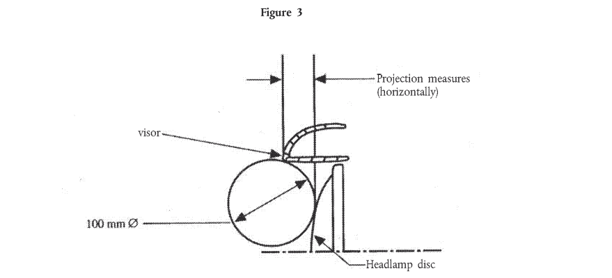
| ... | 2.Definitions | a0c0 |
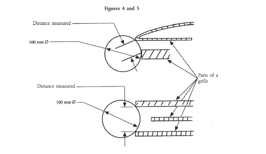
| ... | 3.Application for approval | a0c0 |
| ... | 4.Approvals | a0c0 |
| ... | 5.General Specifications | a0c0 |
| ... | 6.Specific requirements | a0c0 |
| ... | 7.Modifications of vehicle type | a0c0 |
| ... | 8.Conformity of production | a0c0 |
| ... | 9.Penalties for non-conformity of production | a0c0 |
| ... | 10.Production definitely discontinued | a0c0 |
| ... | 11.Names and addresses of technical services responsible for conducting approval tests, and of administrative departments | a0c0 |
| ... | Annexes | a0c0 |
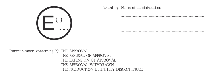
| ... | 1. Communication concerning the approval (or refusal or withdrawal of approval or production definitely discontinued) of a vehicle type with regard to its external projections, pursuant to Regulation No 61 | a0c0 |
| ... | 2. Arrangements of approval marks | a0c0 |
| ... | 3. Procedure for determining the "H" point and the actual seat-back angle and for verifying their relationship to the "R" point and the design seat-back angle | a0c0 |
| ... | Appendix | a0c0 |
| ... | 4. Measurement of projections and distances | a0c0 |
| 1. |
|
a0c0 |
| 1.1. |
This Regulation applies to the external projections of goods vehicles of categories N1, N2 and N3 [1] limited to the "external surface" as defined below. |
a3c0 |
| ... | It does not apply to the exterior rear-view mirrors, including their support, or to the accessories such as aerials and luggage racks. | a0c0 |
| 1.2. | The purpose of this Regulation is to reduce the risk or the severity of injuries sustained by a person coming into contact with the external surface of the vehicle in the event of an impact. | a0c0 |
|
|
|
a3c0 |
| 2. |
|
a0c0 |
| ... | For the purposes of this Regulation: | a0c0 |
| 2.1. | "External surface" means that part of the vehicle forward of the cab rear panel as defined in paragraph 2.5 below, with the exception of the rear panel itself, and includes such items as the front wings, front bumpers and front wheels; | a0c0 |
| 2.2. | "Vehicle approval" means the approval of a vehicle type with regard to its external projections; | a0c0 |
| 2.3. | "Vehicle type" means motor vehicles which do not differ in such essential respects as the "external surface"; | a0c0 |
| 2.4. | "Cab" means that part of the bodywork which constitutes the driver and passenger compartment, including the doors; | a0c0 |
| 2.5. |
"Cab rear panel" means the rearmost part of the external surface of the driver and passenger compartment. Where it is not possible to determine the position of the rear cab panel, for the purposes of this Regulation it would be deemed to be the vertical transversal plane situated 50 cm to the rear of the "R" point of the driver seat, with the seat, if adjustable, located at its rearmost driving position (see Annex 3). However, the manufacturer may, with the agreement of the technical services, request an alternative distance if 50 cm can be shown as being inappropriate for a particular vehicle |
a1c0 |
| 2.6. | "Reference plane" means a horizontal plane passing through the centre of the front wheels or a horizontal plane situated at the height of 50 cm above the ground, whichever is lower; | a0c0 |
| 2.7. | "Floor line" means a line determined as follows: | a0c0 |
| ... | When a vertical-axis cone of undetermined height having its side at an angle of 15deg to the vertical is moved about the external surface of the loaded vehicle so as to remain in contact with the external surface of the body at its lowest point, the floor line is the geometrical trace of the points of contact. In determining the floor line, no account shall be taken of the exhaust pipes or wheels, or of functional mechanical features attached to the under-body such as jacking points, suspension mountings or attachments for use in towing or in case of breakdown. In the spaces at the outside of wheel arches an imaginary surface extending the adjacent external surfaces without change of position shall be assumed. The front bumpers shall be taken into account in determining the floor line. Depending on the type of vehicle, the trace of the floor line may be at either the outer edge of the bumper profile or at the body panel below the bumper. Where there are two or more points of contact at the same time, the lowest point of contact shall be used to determine the floor line, | a0c0 |
| 2.8. | "Radius of curvature" means the radius of the arc of a circle which comes closest to the rounded form of the component under consideration. | a0c0 |
| 2.9. | "Bumper" means the front, lower, outer structure of a vehicle. It includes all structures that are intended to give protection to a vehicle when involved in a low speed frontal collision and also any attachments to this structure. | a2c0 |
| 2.10. | "Bumper cover" means the non-rigid outer surface of a bumper, generally extending across the full width of the front of a vehicle. | a2c0 |
|
|
|
a1c0 |
| 3. |
|
a0c0 |
| 3.1. | The application for approval of a vehicle type with regard to external projections shall be submitted by the vehicle manufacturer or by his duly accredited representative. | a0c0 |
| 3.2. | It shall be accompanied by the under mentioned documents in triplicate: | a0c0 |
| 3.2.1. | photographs of the front and side parts of the vehicle, | a0c0 |
| 3.2.2. | such drawings of the "external surface" which in the opinion of the technical service responsible for conducting the tests are required in order to demonstrate compliance with the provisions of paragraphs 5 and 6 below. | a0c0 |
| 3.3. | The applicant shall submit to the technical service responsible for conducting the approval test: | a0c0 |
| 3.3.1. | either a vehicle representative of the type to be approved or the part(s) of the vehicle deemed essential to carry out the checks and tests required in this Regulation, | a0c0 |
| 3.3.2. | certain parts and samples of the materials used, if so required by the technical service. | a0c0 |
| 4. |
|
a0c0 |
| 4.1. |
If the vehicle submitted for approval pursuant to this Regulation meets the requirements of paragraphs 5. and 6. below, approval of that vehicle type shall be granted. |
a2c0 |
| 4.2. | An approval number shall be assigned to each type approved. Its first two digits (at present 00 for the Regulation in its original form) shall indicate the series of amendments incorporating the most recent major technical amendments made to the Regulation at the time of issue of the approval. The same Contracting Party shall not assign the same number to the same vehicle type having a different external structure or to another vehicle type. | a0c0 |
| 4.3. |
Notice of approval or of refusal |
a2c0 |
| 4.4. | There shall be affixed, conspicuously and in a readily accessible place specified on the approval form, to every vehicle conforming to a vehicle type approved under this Regulation an international approval mark consisting of: | a0c0 |
| 4.4.1. |
a circle surrounding the letter "E" followed by the distinguishing number of the country which has granted approval |
a1c0 |
| 4.4.2. | the number of this Regulation, followed by the letter "R", a dash and the approval number to the right of the circle prescribed in paragraph 4.4.1. | a0c0 |
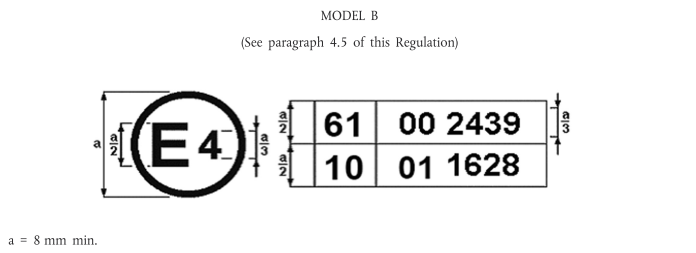
| 4.5. | If the vehicle conforms to a vehicle type approved, under one or more other Regulations annexed to the Agreement, in the country which has granted approval under this Regulation, the symbol prescribed in paragraph 4.4.l need not be repeated, in such a case, the Regulation and approval numbers and the additional symbols of all the Regulations under which approval has been granted in the country which has granted approval under this Regulation shall be placed in vertical columns to the right of the symbol prescribed in paragraph 4.4.1. | a0c0 |
| 4.6. | The approval mark and the additional symbol shall be clearly legible and be indelible. | a0c0 |
| 4.7. | The approval mark shall be placed close to or on the vehicle data plate affixed by the manufacturer. | a0c0 |
| 4.8. | Annex 2 to this Regulation gives examples of arrangements of approval marks. | a0c0 |
|
|
|
a1c0 |
| 5. |
|
a0c0 |
| 5.1. | The provisions of this Regulation shall not apply to those parts of the "external surface" of the vehicle which, with the vehicle in the unladen condition, with doors, windows, access lids, etc., in the closed position are either: | a0c0 |
| 5.1.1. | outside a zone having as its upper limit a horizontal plane situated 2,00 m above the ground and as its lower limit either the reference plane defined in paragraph 2.6 or the floor line defined in paragraph 2.7 as selected by the manufacturer, or | a0c0 |
| 5.1.2. | located so that, in static condition, they cannot be contacted by a sphere 100 mm in diameter. | a0c0 |
| 5.1.3. | Where the reference plane is the lower limit of the zone, account shall be taken only of the parts of the vehicle falling between two vertical planes, one touching the external surface of the vehicle and the other parallel to it at a distance of 80 mm towards the interior of the vehicle. | a0c0 |
| 5.2. | The "external surface" of the vehicle shall not exhibit, directed outwards, any port likely to catch on pedestrians, cyclists or motor cyclists. | a0c0 |
| 5.3. | Any components specified in paragraph 6 below, shall not exhibit, directed outwards, any pointed or sharp parts or any projections of such shape, dimensions, direction or hardness as to be likely to increase the risk or seriousness of bodily injury to a person hit by the external surface or brushing against it in the event of a collision. | a0c0 |
| 5.4. | Projecting parts of the outer surface having a hardness of not more than 60 Shore A, may have a radius of curvature lower than the values prescribed under paragraph 6 below. | a0c0 |
| 6. |
|
a0c0 |
| 6.1. | Ornaments, commercial symbols, letters and numbers of commercial markings | a0c0 |
| 6.1.1. | Ornaments, commercial symbols, letters and numbers of commercial markings shall not have any radius of curvature of less than 2,5 mm. This requirement does not apply to those parts if they do not protrude more than 5 mm from the surrounding surface; however, in this case their edges directed outwards shall be blunted. | a0c0 |
| 6.1.2. | Ornaments, commercial symbols, letters and numbers of commercial markings, which project more than 10 mm from the surrounding surface shall retract, become detached or bend over under a force of 10 daN exerted at their most salient point in any direction in a plane approximately parallel to the surface on which they are mounted. To apply 10 daN force a flat-ended ram of not more than 50 mm diameter shall be used. Where this is not possible, an equivalent method shall be used. After the ornaments are retracted, detached or bent over, the remaining portion shall not project more than 10 mm and shall not have any pointed, sharp or cutting edges. | a0c0 |
| 6.2. | Headlamp visors and rims | a0c0 |
| 6.2.1. | Projecting visors and rims shall be permitted on headlamps provided that their projection as measured in relation to the external transparent surface of the headlamp does net exceed 30 mm and their radius of curvature is at least 2,5 mm throughout. | a0c0 |
| 6.2.2. | Retracting headlamps shall meet the requirements of paragraph 6.2.1 above in both operative and retracted positions. | a0c0 |
| 6.2.3. | The provisions of paragraph 6.2.1 above shall not apply to headlamps recessed in the body, or where the headlamp is overhung by the body, provided the bodywork conforms to the requirements of paragraph 5.2 above. | a0c0 |
| 6.3. | Grilles | a0c0 |
| ... | Parts of grilles shall exhibit a radius of curvature of: | a0c0 |
| ... | - not less than 2,5 mm if the distance between adjacent parts is more than 40 mm, | a0c0 |
| ... | - not less than 1 mm if the distance is between 25 mm and 40 mm, | a0c0 |
| ... | - not less than 0,5 mm if the distance is less than 25 mm. | a0c0 |
| 6.4. | Windscreen and headlamp cleaning devices | a0c0 |
| 6.4.1. | The above-mentioned devices shall be such that the wiper shafts have a protective covering with a radius of curvature of not less than 2,5 mm and a surface area of not less than 150 mm 2 measured in the projection of a section not further than 6,5 mm from the most protruding point. | a0c0 |
| 6.4.2. | Nozzles for windscreen washer and headlamp cleaning devices shall have a radius of curvature of not less than 2,5 mm. Those protruding less than 5 mm shall have blunted outward facing edges. | a0c0 |
| 6.5. | Protective devices (bumpers) | a0c0 |
| 6.5.1. | The ends of front protective devices shall be turned in towards the external surface of the body. | a0c0 |
| 6.5.2. |
The component of the front protective devices shall be so designed that all rigid surfaces facing outwards have a radius of curvature of not less than 5 mm. |
a2c0 |
| 6.5.3. | Equipment such as towing hitches and winches shall not protrude beyond the foremost surface of the bumper. However, winches may protrude beyond the foremost surface of the bumper provided they are covered when not in use by a suitable protective covering having a radius of curvature of not less than 2,5 mm. | a0c0 |
| 6.5.4. | The requirements of paragraph 6.5.2 shall not apply to parts of the bumper or parts mounted on or inset in the bumper which project less than 5 mm. The edges of devices projecting less than 5 mm shall be blunted. With respect to devices mounted on the bumpers and referred to in other paragraphs of this Regulation, the particular requirements contained in this Regulation shall remain applicable. | a0c0 |
| 6.6. | Handles, hinges, pushbuttons of doors, luggage compartments bonnets, vents, access flaps and grab handles | a0c0 |
| 6.6.1. | The above parts shall not protrude more than: 30 mm in the case of pushbuttons, 70 mm in the case of grab handles and bonnet-fasteners, and 50 mm in all other cases. They shall have radii of curvature of not less than 2,5 mm. | a0c0 |
| 6.6.2. | If lateral door handles rotate to operate, they shall meet one or other of the following requirements: | a0c0 |
| 6.6.2.1. | In the case of handles which rotate parallel to the plane of the door the open end of handles must be directed towards the rear. The end of such handles shall be turned back towards the plane of the door and fitted into a protective surround or be recessed; | a0c0 |
| 6.6.2.2. | Handles which pivot outwards in any direction which are not parallel to the plane of the door shall, when in the closed position, be enclosed in a protective surround or be recessed. The open end shall face either rearwards or downwards. | a0c0 |
| ... | Nevertheless, handles which do not comply with this last condition may be accepted if: | a0c0 |
| ... | - they have an independent return mechanism, | a0c0 |
| ... | - should the return mechanisms fail, they cannot project more than 15 mm, | a0c0 |
| ... | - they, in such opened position, have a radius of curvature not less than 2,5 mm (this requirement does not apply if in maximum opened position the projection is less than 5 mm, in which case the angles of the parts fa | a0c0 |
| 6.7. | Running boards and steps | a0c0 |
| ... | The edges of running boards and steps shall be rounded. | a0c0 |
| 6.8. | Lateral air and rain deflectors and window anti-smear air deflectors | a0c0 |
| ... | Edges capable of being directed outwards shall have a radius of curvature of not less than 1 mm. | a0c0 |
| 6.9. | Sheet metal edges | a0c0 |
| ... | Sheet metal edges are permitted provided that the edge is folded back towards the body so that it cannot be touched by a sphere of 100 mm diameter or is provided with a protective covering having a radius of curvature of not less than 2,5 mm. | a0c0 |
| 6.10. | Wheel nuts, hub caps and protective devices | a0c0 |
| 6.10.1. | The wheel nuts, hub caps and protective devices shall not exhibit any fin-shaped projections. | a0c0 |
| 6.10.2. | When the vehicle is travelling in a straight line, no part of the wheels, other than the tyres, situated above the horizontal plane, passing through their axis of rotation, shall project beyond the vertical projection in a horizontal plane, of the body panel edge above the wheel. However, if functional requirements so warrant, the protective devices which cover wheel nuts and hubs may project beyond the vertical projection of the body panel edge above the wheel, on condition that radius of curvature of the surface of the projection part is not less than 5 mm and that the projection beyond the vertical projection of the body panel edge above the wheel in no case exceeds 30 mm. | a0c0 |
| 6.10.3. | Protective device(s) conforming to paragraph 6.10.2 above shall be fitted if bolts or nuts protrude beyond the projection of the outside surface of the tyre (the part of the tyre situated above the horizontal plane passing through the axis of rotation of the wheel). | a0c0 |
| 6.11. | Jacking points and exhaust pipe(s) | a0c0 |
| 6.11.1. | The jacking points (if any) and exhaust pipe or pipes shall not project more than 10 mm beyond the vertical projection of the floor line or the vertical projection of the intersection of the reference plane with the external surface of the vehicle. | a0c0 |
| 6.11.2. | Notwithstanding the above requirement, an exhaust pipe may project more than 10 mm provided that its edges are rounded at the end to a radius of curvature of not less than 2,5 mm.. | a0c0 |
| 7. |
|
a0c0 |
| 7.1. |
(a) Decide, in consultation with the manufacturer, that a new type-approval is to be granted, or (b) Apply the procedure contained in paragraph 7.1.1. (Revision) and, if applicable, the procedure contained in paragraph 7.1.2. (Extension). |
a2c0 |
| 7.1.1. |
When particulars recorded in the information folder have changed and the Type Approval Authority considers that the modifications made are unlikely to have an appreciable adverse effect and that in any case the vehicle still complies with the requirements, the modification shall be designated a "Revision". In such a case, the Type Approval Authority shall issue the revised pages of the information folder as necessary, marking each revised page to show clearly the nature of the modification and the date of re-issue. A consolidated updated version of the information folder, accompanied by a detailed description of the modification, shall be deemed to meet this requirement. |
a2c0 |
| 7.1.2. |
The modification shall be designated an "Extension" if, in addition to the change of the particulars recorded in the information folder, (a) Further inspections or tests are required, or (b) Any information on the communication document (with the exception of its attachments) has changed, or (c) Approval to a later series of amendments is requested after its entry into force. |
a2c0 |
| 7.2. |
Confirmation or refusal of approval, specifying the alterations shall be communicated by the procedure specified in paragraph 4.3. above to the Parties to the Agreement which apply this Regulation. |
a2c0 |
| 8. |
|
a0c0 |
| 8.1. | Every vehicle bearing an approval mark as prescribed under this Regulation shall conform, with regard to external projections, to the vehicle type approved. | a0c0 |
| 8.2. | In order to verify conformity as prescribed in paragraph 8.1 above a sufficient number of random checks shall be made oh serially manufactured vehicles bearing the approval mark required by this Regulation. | a0c0 |
| 9. |
|
a0c0 |
| 9.1. | The approval granted in respect of a vehicle type pursuant to this Regulation may be withdrawn if the requirements laid down in paragraph 6 above are not complied with or if the vehicle has failed to pass the test prescribed in Annex 3. | a0c0 |
| 9.2. |
If a Party to the Agreement applying this Regulation withdraws an approval it has previously granted, it shall forthwith so notify the other Contracting Parties applying this Regulation, by means of |
a2c0 |
| 10. |
|
a0c0 |
| ... |
If the holder of the approval completely ceases to manufacture a type of vehicle approved in accordance with this Regulation, he shall so inform the Type Approval Authority which granted the approval. Upon receiving the relevant communication, that authority shall inform thereof the other Parties to the Agreement applying this Regulation by means of |
a2c0 |
| 11. |
|
a0c0 |
| ... | The Parties to the Agreement which apply this Regulation shall communicate to the United Nations Secretariat the names and addresses of the technical services responsible for conducting approval tests and of the administrative departments which grant approval and to which forms certifying approval or refusal or withdrawal of approval, issued in other countries, are to be sent. | a0c0 |
| A1 |
|
a0c0 |
| A1 |
|
a0c0 |
| A1 |
|
a0c0 |
| A1 | of a vehicle type with regard to its external projections, pursuant to Regulation No. 61 | a0c0 |
| A1 | Approval No......................... | a0c0 |
| A1 1. | Trade name or mark of the motor vehicle: | a0c0 |
| A1 2. | Vehicle type: | a0c0 |
| A1 3. | Manufacturer's name and address: | a0c0 |
| A1 4. | Name and address of manufacturer's representative (if applicable): | a0c0 |
| A1 5. | Vehicle submitted for approval on: | a0c0 |
| A1 6. | Technical service responsible for conducting approval tests: | a0c0 |
| A1 7. | Date of report issued by that service: | a0c0 |
| A1 8. | Number of report issued by that service: | a0c0 |
| A1 9. |
Approval: |
a2c0 |
| A1 10. | Position of the approval mark on the vehicle: | a0c0 |
| A1 11. | Position of cab rear panel with reference to "R" point of the driver's seat where applicable (see paragraph 2.5): | a0c0 |
| A1 12. | Lower limit of the zone specified in paragraph 5.1.1: | a0c0 |
| A1 | Reference plane/floor line [2] | a0c0 |
| A1 13. | Place: | a0c0 |
| A1 14. | Date: | a0c0 |
| A1 15. | Signature: | a0c0 |
| A1 16. | Photographs of the front, rear and side parts of the cab forward of the rear panel, bearing the approval number shown above, are annexed to this communication. | a0c0 |
|
A1 |
|
a0c0 |
|
A1 |
|
a0c0 |
| A2 |
|
a0c0 |
| A2 |
|
a0c0 |
| A2 |

|
a0c0 |
| A2 | The above approval mark affixed to a commercial vehicle shows that the vehicle type concerned has, with regard to external projections, been approved in the Netherlands (E 4) pursuant to Regulation No 61 under approval number 002439. The approval number indicates that the approval was granted in accordance with the requirements of Regulation No 61 in its original form. | a0c0 |
| A2 |
|
a0c0 |
| A2 | The above approval mark affixed to a commercial vehicle shows that the vehicle type concerned has been approved in the Netherlands (E 4) pursuant to Regulations No 61 and No 10 [*]. The approval numbers indicate that, at the dates when the respective approvals were given, Regulation No 61 had not been modified and Regulation No 10 already included the 01 series of amendments. | a0c0 |
|
A2 |
|
a0c0 |
| A3 |
|
a0c0 |
| A3 |
|
a0c0 |
| A3 1. | DEFINITIONS | a0c0 |
| A3 1.1. | The "H" point, which indicates the position of a seated occupant in the passenger compartment, is the trace, in a longitudinal vertical plane, of the theoretical axis of rotation between the legs and the torso of a human body represented by the manikin described in paragraph 3 below. | a0c0 |
| A3 1.2. | The "R" point or "seating reference point" is the reference point specified by the manufacturer which: | a0c0 |
| A3 1.2.1. | has coordinates determined in relation to the vehicle structure; | a0c0 |
| A3 1.2.2. | corresponds to the theoretical position of the point of torso/legs rotation ("H" point) for the lowest and most rearward normal driving position or position of use given to each seat provided by the vehicle manufacturer. | a0c0 |
| A3 1.3. | "Seat-back angle" means the inclination of the seat back in relation to the vertical. | a0c0 |
| A3 1.4. | "Actual seat-back angle" means the angle formed by the vertical through the "H" point with the torso reference line of the human body represented by the manikin described in paragraph 3 below. | a0c0 |
| A3 1.5. | "Design seat-back angle" means the angle prescribed by the manufacturer which: | a0c0 |
| A3 1.5.1. | determines the seat-back angle for the lowest and most rearward normal driving position or position of use given to each seat by the vehicle manufacturer; | a0c0 |
| A3 1.5.2. | is formed at the "R" point by the vertical and the torso reference line; | a0c0 |
| A3 1.5.3. | corresponds theoretically to the actual seat-back angle. | a0c0 |
| A3 2. | DETERMINATION OF "H" POINTS AND ACTUAL SEAT-BACK ANGLES | a0c0 |
| A3 2.1. | An "H" point and an "actual seat-back angle" shall be determined for each seat provided by the manufacturer. If the seats in the same row can be regarded as similar (bench seat, identical seats, etc.) only one "H" point and one "actual seat-back angle" shall be determined for each row of seats, the manikin described in paragraph 3 below being seated in a place regarded as representative for the row. This place shall be: | a0c0 |
| A3 2.1.1. | in the case of the front row, the driver's seat; | a0c0 |
| A3 2.1.2. | in the case of the rear row or rows, an outer seat. | a0c0 |
| A3 2.2. | When an "H" point and an "actual seat-back angle" are being determined, the seat considered shall be placed in the lowest and most rearward normal driving position or position of use provided for it by the manufacturer. The seat back shall, if its inclination is adjustable, be locked as specified by the manufacturer or, in the absence of any specification, to an actual seat-back angle as near as possible to 25 deg from the vertical. | a0c0 |
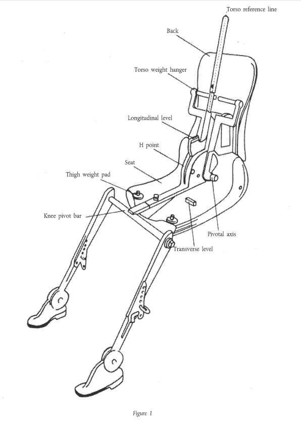
| A3 3. | DESCRIPTION OF THE MANIKIN | a0c0 |
| A3 3.1. | A three-dimensional manikin of a mass and contour corresponding to these of an adult male of average height shall be used. Such a manikin is depicted in figures 1 and 2 below. | a0c0 |
| A3 3.2. | The manikin shall comprise: | a0c0 |
| A3 3.2.1. | Two components, one simulating the back and the other the seat of the body, pivoting on an axis representing the axis of rotation between the torso and the thigh; the trace of this axis on the side of the manikin is the manikin's "H" point; | a0c0 |
| A3 3.2.2. | Two components simulating the legs and pivotally attached to the component simulating the seat; and | a0c0 |
| A3 3.2.3. | Two components simulating the feet and connected to the legs by pivotal joints simulating ankles. | a0c0 |
| A3 3.2.4. | In addition, the component simulating the seat of the body shall be provided with a level enabling its transverse orientation to be verified. | a0c0 |
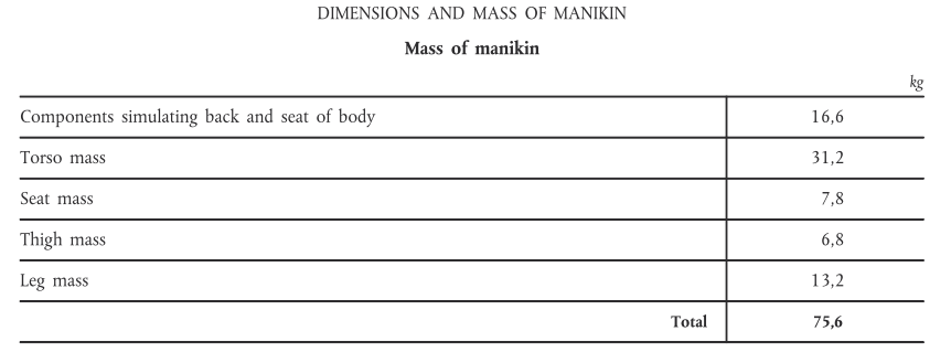
| A3 3.3. | Body-segment mass shall be attached at appropriate points representing the corresponding centres of gravity so as to bring the total mass of the manikin up to about 75,6 kg. Details of the various masses are given in the table in figure 2 of the Appendix to this Annex. | a0c0 |
| A3 3.4. | The torso reference line of the manikin is taken into account by a straight line passing through the joint between the leg and the pelvis and the theoretical joint between the neck and the thorax (see figure 1 of the Appendix to this Annex). | a0c0 |
| A3 4. | SETTING UP THE MANIKIN | a0c0 |
| A3 | The three-dimensional manikin shall be set up in the following manner: | a0c0 |
| A3 4.1. | The vehicle shall be placed on a horizontal plane and the seats adjusted as prescribed in paragraph 2.2 above; | a0c0 |
| A3 4.2. | The seat to be tested shall be covered with a piece of cloth to facilitate the correct setting-up of the manikin; | a0c0 |
| A3 4.3. | The manikin shall be placed on the seat concerned, its pivotal axis being perpendicular to the longitudinal plane of symmetry of the vehicle; | a0c0 |
| A3 4.4. | The feet of the manikin shall be placed as follows: | a0c0 |
| A3 4.4.1. | In the front seats, in such a way that the level verifying the transverse orientation of the seat of the manikin is brought to the horizontal; | a0c0 |
| A3 4.4.2. | In the rear seats, so far as possible in such a way as to be in contact with the front seats. If the feet then rest on parts of the floor which are at different levels, the foot which first comes into contact with the front seat shall serve as a reference point and the other foot shall be so arranged that the level enabling the transverse orientation of the seat of the manikin to be verified is brought to the horizontal; | a0c0 |
| A3 4.4.3. | If the "H" point is being determined at a centre seat, the feet shall be placed one on each side of the tunnel; | a0c0 |
| A3 4.5. | The masses shall be placed on the thighs, the level verifying the transverse orientation of the seat of the manikin shall be brought to the horizontal, and the weights shall be placed on the component representing the seat of the manikin; | a0c0 |
| A3 4.6. | The manikin shall be moved away from the seat back by means of the knee-pivot bar and the back of the manikin shall be pivoted forwards. The manikin shall be repositioned on the seat of the vehicle by being slid backwards on its seat until resistance is encountered, the back of the manikin then being replaced against the seat back; | a0c0 |
| A3 4.7. | A horizontal load of approximately 10 ± 1 daN shall be applied to the manikin twice. The direction and point of application of the load are shown by a black arrow in figure 2; | a0c0 |
| A3 4.8. | The masses shall be installed on the right and left sides and the torso weights shall then be placed in position. The transverse level of the manikin shall be kept horizontal; | a0c0 |
| A3 4.9. | The transverse level of the manikin being kept horizontal, the back of the manikin shall be pivoted forwards until the torso weights are above the "H" point, so as to eliminate any friction with the seat back; | a0c0 |
| A3 4.10. | The back of the manikin shall be gently moved rearwards so as to complete the setting-up operation. The transverse level of the manikin shall be horizontal. If it is not, the procedure described above shall be repeated. | a0c0 |
| A3 5. | RESULTS | a0c0 |
| A3 5.1. | When the manikin has been set up as described in paragraph 4 above, the "H" point and the actual seat-back angle of the vehicle seat in question are constituted by the "H" point and the angle of inclination of the manikin's torso reference line. | a0c0 |
| A3 5.2. | The coordinates of the "H" point in relation to three mutually perpendicular planes, and the actual seat-back angle, shall be measured for comparison with the data supplied by the vehicle manufacturer. | a0c0 |
| A3 6. | VERIFYING THE RELATIVE POSITIONS OF THE "R" AND "H" POINTS AND THE RELATIONSHIP BETWEEN THE DESIGN SEAT-BACK ANGLE AND THE ACTUAL SEAT-BACK ANGLE | a0c0 |
| A3 6.1. | The results of the measurements carried out in conformity with paragraph 5.2 for the "H" point and the actual seat- back angle shall be compared with the coordinates of the "R" point and the design seat-back angle as supplied by the vehicle manufacturer. | a0c0 |
| A3 6.2. | The relative positions of the "R" point and the "H" point and the relationship between the design seat-back angle and the actual seat-back angle shall be considered satisfactory for the seat in question if the "H" point, as defined by its coordinates, lies within a square of 50 mm side whose diagonals intersect at the "R" point, and if the actual seat- back angle is within 5 deg of the design seat-back angle. | a0c0 |
| A3 6.2.1. | If these conditions are met, the "R" point and the design seat-back angle shall be used for the test and, if necessary, the manikin shall be so adjusted that the "H" point coincides with the "R" point and the actual seat-back angle coincides with the design seat-back angle. | a0c0 |
| A3 6.3. | If the "H" point or the actual seat-back angle does not satisfy the requirements of paragraph 6.2 above, the "H" point or the actual seat-back angle shall be determined twice more (three times in all). If the results of two of these three operations satisfy the requirements, the result of the test shall be considered satisfactory. | a0c0 |
| A3 6.4. | Unless at least two of the three test results satisfy the requirements of paragraph 6.2, the result of the test shall be considered to be not satisfactory. | a0c0 |
| A3 6.5. | If the situation described in paragraph 6.4 above arises, or if verification cannot be effected because the manufacturer has failed to supply information regarding the position of the "R" point or regarding the design seat-back angle, the average of the results of the three determinations may be used and be regarded as applicable in all cases where the "R" point or the design seat-back angle is referred to in this Regulation. | a0c0 |
| A3 |
|
a0c0 |
| A3 |
|
a0c0 |
| A3 |
|
a0c0 |
| A3 |
|
a0c0 |
| A3 |

|
a0c0 |
| A4 |
|
a0c0 |
| A4 |
|
a0c0 |
| A4 1. | METHOD OF DETERMINING THE DIMENSIONS OF THE PROJECTION OF A PART FITTED ON THE EXTERNAL SURFACE | a0c0 |
| A4 1.1. | The dimensions of the projection of a part mounted on a convex panel may be determined either directly or by reference to a drawing of an appropriate section of the part in the fitted position. | a0c0 |
| A4 1.2. | If the Projection of a part mounted on a panel other than convex cannot be determined by simple measurement, it shall be determined by the maximum variation in the distance between the reference line of the panel and the centre of a sphere of 100 mm diameter when the sphere is moved in constant contact with the part. An example of the use of this method is given in figure 1. | a0c0 |
| A4 1.3. | For grab handles, the projection shall be measured in relation to a plane passing through the points of attachment. An example is given in figure 2. | a0c0 |
| A4 2. | METHOD OF DETERMINING THE PROJECTION OF HEADLAMP VISORS AND RIMS | a0c0 |
| A4 2.1. | The projection from the outer surface of the headlamp shall be measured horizontally from the point of contact of a sphere of 100 mm diameter, as shown in figure 3. | a0c0 |
| A4 3. | METHOD OF DETERMINING THE DISTANCE BETWEEN PARTS OF A GRILLE | a0c0 |
| A4 3.1. | The distance between parts of a grille shall be the distance between two planes passing through the points of contact of the sphere and perpendicular to the line joining the points of contact. Examples of the use of this method are given in figures 4 and 5. | a0c0 |
| A4 |
|
a0c0 |
| A4 |

|
a0c0 |
| A4 |
|
a0c0 |
| A4 |
|
a0c0 |