| ... | Regulation | a0c0 |
| ... | 1. Scope | a0c0 |
| ... | 2. General requirements | a0c0 |
| ... | 3. Definitions common to Parts I, II and III | a0c0 |
| ... | Part I. Approval of RUPDs | a0c0 |
| ... | 4. Definitions | a0c0 |
| ... | 5. Application for approval | a0c0 |
| ... | 6. Approval | a0c0 |
| ... | 7. Requirements | a0c0 |
| ... | 8. Conformity of production | a0c0 |
| ... | 9. Penalties for non-conformity of production | a0c0 |
| ... | 10. Modification and extension of approval of an RUPD type | a0c0 |
| ... | 11. Production definitively discontinued | a0c0 |
| ... | 12. Names and addresses of Technical Services responsible for conducting approval tests, and of Type Approval Authorities | a0c0 |
| ... | Part II. Approval of a vehicle with regard to the installation of an RUPD of an approved type | a0c0 |
| ... | 13. Definitions | a0c0 |
| ... | 14. Application for approval | a0c0 |
| ... | 15. Approval | a0c0 |
| ... | 16. Requirements for installation of an approved RUPD | a0c0 |
| ... | 17. Conformity of production | a0c0 |
| ... | 18. Penalties for non conformity of production | a0c0 |
| ... | 19. Modification and extension of approval of a vehicle type | a0c0 |
| ... | 20. Production definitively discontinued | a0c0 |
| ... | 21. Names and addresses of Technical Services responsible for conducting approval tests, and of Type Approval Authorities | a0c0 |
| ... | Part III. Approval of a vehicle with regard to its rear underrun protection (RUP) | a0c0 |
| ... | 22. Definitions | a0c0 |
| ... | 23. Application for approval | a0c0 |
| ... | 24. Approval | a0c0 |
| ... | 25. Requirements for RUP | a0c0 |
| ... | 26. Conformity of production | a0c0 |
| ... | 27. Penalties for non conformity of production | a0c0 |
| ... | 28. Modification and extension of approval of a vehicle type | a0c0 |
| ... | 29. Production definitively discontinued | a0c0 |
| ... | 30. Names and addresses of Technical Services responsible for conducting approval tests, and of Type Approval Authorities | a0c0 |
| ... | Part IV. Transitional provisions | a0c0 |
| ... | 31. Transitional provisions | a0c0 |
| ... | Annexes | a0c0 |
| ... | 1 Communication (Part I) | a0c0 |
| ... | 2 Communication (Part II) | a0c0 |
| ... | 3 Communication (Part III) | a0c0 |
| ... | 4 Arrangements of approval marks | a0c0 |
| ... | 5 Test conditions and procedures | a0c0 |
| ... | 6 Specific vehicles | a0c0 |
| ... | 7 Requirements for different vehicle categories | a0c0 |
| ... | a0c0 | |
| 1. |
|
a0c0 |
| 1.1. | This Regulation applies to: | a0c0 |
| 1.1.1. | PART I: the RUPDs which are intended to be fitted to vehicles of categories M, N and O[1]; | a0c0 |
| 1.1.2. | PART II: the installation on vehicles of categories M, N and O[1] of RUPDs which have been type approved to Part I of this Regulation; | a0c0 |
| 1.1.3. | PART III: vehicles of categories M, N and O[1] equipped with an RUPD which has not been separately approved according to Part I of this Regulation or so designed and/or equipped that its component parts can be regarded as totally or partially fulfilling the function of the RUPD; | a0c0 |
| 1.1.4. | Vehicles of categories M1, M2, M3, N1, O1 and O2[1] on grounds of rear underrun protection. | a0c0 |
| 1.2. | This Regulation does not apply to: | a0c0 |
| 1.2.1. | Tractive units for articulated vehicles; | a0c0 |
| 1.2.2. | Trailers specially designed and constructed for the carriage of very long loads of indivisible length, such as timber, steel bars, etc.; | a0c0 |
| 1.3. | Vehicles where any RUPD (e.g. fixed, removable, foldable, adjustable, etc.) is incompatible with their use on traffic roads may be partly or fully exempted from this Regulation, subject to the decision of the Type Approval Authority. | a0c0 |
|
|
|
a0c0 |
| 2. |
|
a0c0 |
| 2.1. | All vehicles shall be so constructed and/or equipped as to offer effective protection over their whole width against under-running of vehicles mentioned in paragraph 1. of this Regulation in the event of rear collision with vehicles of category M1 and N1.[1] | a0c0 |
| 2.2. | The vehicle shall be tested under the conditions as laid down in paragraph 2. of Annex 5. | a0c0 |
| 2.3. | Any vehicle in one of the categories M1, M2, M3, N1, O1 or O2 shall be deemed to satisfy the condition set out above: | a0c0 |
| ... | (a) If it satisfies the same conditions as set out in Part II or Part III, or | a0c0 |
| ... | (b) If the ground clearance of the rear part of the unladen vehicle does not exceed 550 mm over a width which is not shorter than that of the rear axle by more than 100 mm on either side (excluding any tyre bulging close to the ground), or | a0c0 |
| ... | (c) If, in case of vehicles of categories O1 and O2 where the tyres project for more than half of their width outside the bodywork (excluding the wheel guards) or outside the chassis in the absence of bodywork, the ground clearance of the rear part of the unladen vehicle does not exceed 550 mm over a width which is not less than 100 mm deducted from the distance measured between the innermost points of the tyres (excluding any tyre bulging close to the ground), on either side. | a0c0 |
| ... | Where there is more than one rear axle, the width to be considered is that of the widest. | a0c0 |
| ... | The requirements of paragraphs 2.3.(b) and 2.3.(c) above shall be satisfied at least on a line: | a0c0 |
| ... | (a) At a distance of not more than 450 mm from the rear extremity of the vehicle; | a0c0 |
| ... | (b) That may have interruptions totalling not more than 200 mm. | a0c0 |
| 2.4. |
Any vehicle of category G will be deemed to satisfy the condition for the ground clearance set out in this Regulation, if the departure angle (ISO 612:1978) does not exceed: |
a1c0 |
| 3. |
|
a0c0 |
| 3.1. | For the purpose of this Regulation: | a0c0 |
| 3.1.1. |
"Unladen mass" means the mass of the vehicle in running order, unoccupied and unladen but complete with fuel, coolant, lubricant, tools and a spare wheel (if provided as standard equipment by the vehicle manufacturer); |
a0c0 |
| 3.1.2. | "Maximum mass" means the mass stated by the vehicle manufacturer to be technically permissible (this mass may be higher than the "permissible maximum mass" laid down by the national administration); | a0c0 |
| 3.1.3. | An "RUPD" normally consists of a cross-member and links to the chassis side members or other structural members of the vehicle; | a0c0 |
| 3.1.4. | "Separate cab" means a cab attached to the vehicle's frame by specific links and which has no common part with the cargo area. | a0c0 |
| 3.1.5. |
“Aerodynamic devices and equipment” mean devices that are designed to reduce the aerodynamic drag of road vehicles. |
a2c0 |
| ... |
|
a0c0 |
| 4. |
|
a0c0 |
| 4.1. | For the purpose of Part I of this Regulation: | a0c0 |
| 4.1.1. | "Approval of an RUPD" means the approval of such a type of RUPD with respect to the requirements laid down in paragraph 7. below; | a0c0 |
| 4.1.2. | "Type of RUPD" means RUPDs which do not differ with respect to the essential characteristics such as shape, dimensions, attachment, materials and the markings cited in paragraph 5.2.2. below. | a0c0 |
| 5. |
|
a0c0 |
| 5.1. | The application for approval of an RUPD shall be submitted by the manufacturer of the RUPD or by his duly accredited representative. | a0c0 |
| 5.2. | For each type of RUPD the application shall be accompanied by: | a0c0 |
| 5.2.1. | Documentation in triplicate giving a description of the technical characteristics of the RUPD: its dimensions, lines and constituent materials and the method of its installation; | a0c0 |
| 5.2.2. | A sample of the type of RUPD: the sample shall be clearly and indelibly marked on all its main components with the applicant's trade name or mark and the type designation. | a0c0 |
| 5.3. | An RUPD representative of the type to be approved shall be submitted to the Technical Service responsible for conducting the approval tests. | a0c0 |
| 5.4. | The Type Approval Authority shall verify the existence of satisfactory arrangements for ensuring effective control of the conformity of production before type approval is granted. | a0c0 |
| 6. |
|
a0c0 |
| 6.1. | If the RUPD submitted for approval pursuant to this Regulation meets the requirements of paragraph 7. below, approval of that type of RUPD shall be granted. | a0c0 |
| 6.2. | An approval number shall be assigned to each type approved. Its first two digits (at present 03 corresponding to the 03 series of amendments) shall indicate the series of amendments incorporating the most recent major technical amendments made to the Regulation at the time of issue of the approval. The same Contracting Party may not assign the same number to another type of rear underrun protective device. | a0c0 |
| 6.3. |
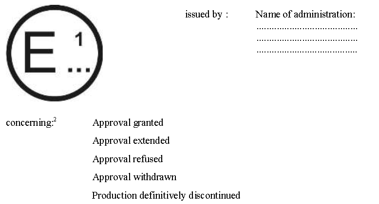
Notice of approval, or of extension or of refusal of approval of a type of RUPD pursuant to this Regulation shall be communicated to the Parties to the 1958 Agreement which apply this Regulation, by means of a form conforming to the model in Annex 1 to this Regulation. |
a0c0 |
| 6.4. | There shall be affixed, conspicuously and in a readily accessible place specified on the approval form, to every RUPD conforming to a type of RUPD approved under this Regulation an international approval mark consisting of: | a0c0 |
| 6.4.1. | A circle surrounding the letter "E" followed by the distinguishing number of the country which has granted approval;[2] | a0c0 |
| 6.4.2. | The number of this Regulation, followed by the letter "R", a dash and the approval number to the right of the circle prescribed in paragraph 6.4.1. | a0c0 |
| 6.5. | The approval mark shall be clearly legible and be indelible. | a0c0 |
| 6.6. | Annex 4 to this Regulation gives examples of arrangements of approval marks. | a0c0 |
|
|
|
a0c0 |
| 7. |
|
a0c0 |
| 7.1. |
The cross-member shall have a section height of at least 120 mm. The lateral extremities of the cross member shall not bend to the rear or have a sharp outer edge; this condition is fulfilled when the lateral extremities of the cross-member are rounded on the outside and have a radius of curvature of not less than 2.5 mm. |
a0c0 |
| ... | RUPD intended to be fitted on vehicles of categories M, N1, N2 with a maximum mass not exceeding 8 t, O1, O2, on vehicles of category G and on vehicles fitted with a platform lift, the cross-member shall have a section height of at least 100 mm. | a0c0 |
| 7.2. | The RUPD may be so designed to have several positions at the rear of the vehicle. In this event, there shall be a guaranteed method of securing it in the service position so that any unintentional change of position is precluded. The force applied by the operator to vary the position of the device shall not exceed 40 daN. | a0c0 |
| For RUPD that are designed to have several positions at the rear of the vehicle, a label shall be provided either with (a) symbol(s) or in the language(s) of the country where the device is sold to inform the operator about the standard position of the RUPD to offer effective protection against under-running. | a0c0 | |
| Label minimum size: 60 x 120 mm | a0c0 | |
| 7.3. |
The RUPD shall offer adequate resistance to forces applied parallel to the longitudinal axis of the vehicle. (This shall be demonstrated in accordance with the test procedure and test conditions specified in Annex 5 to this Regulation.) The maximum horizontal deflection of the RUPD observed during and after the application of the test forces specified in Annex 5 shall be recorded on the type approval communication (Annex 1, item 8). |
a0c0 |
| 7.4. | For vehicles fitted with a platform lift at the rear, the underrun device may be interrupted for the purposes of the mechanism. In this case, the following special requirements apply: | a0c0 |
| 7.4.1. |
The maximum lateral clearance measured between the elements of the underrun device and the elements of the platform lift, which move through the interruption when the lift is operated and which make the interruption necessary, may amount to no more than 2.5 cm. |
a0c0 |
| 7.4.2. | The individual elements of the underrun protection, including those outboard of the lift mechanism, where provided, shall have an effective surface area, in each case, of at least 420 cm2. | a0c0 |
| 7.4.3. | For cross-members with a section height of less than 120 mm, the individual elements of the underrun protection, including those outboard of the lift mechanism, where provided, shall have an effective surface area, in each case, of at least 350 cm2. | a0c0 |
| 7.4.4. | In the case of vehicles having a width of less than 2,000 mm and where it is impossible to achieve the requirements of paragraphs 7.4.2. and 7.4.3., the effective surface may be reduced on the condition that the resistance criteria are met. | a0c0 |
| 8. |
|
a0c0 |
| ... | The conformity of production procedures shall comply with those set out in the Agreement, Schedule 1 (E/ECE/TRANS/505/Rev.3), with the following requirements: | a0c0 |
| 8.1. |
Every rear underrun protective device approved under this Regulation shall be so manufactured as to conform to the type approved by meeting the requirements set out in paragraph 7. above. |
a0c0 |
| 8.2. | The Type Approval Authority that has granted type approval may at any time verify the conformity control methods applied in each production facility. The normal frequency of these verifications shall be one every two years. | a0c0 |
| 9. |
|
a0c0 |
| 9.1. | The approval granted in respect of a type of RUPD pursuant to this Regulation may be withdrawn if the requirements set forth above are not met or if the protective device has failed to pass the test prescribed in Annex 5. | a0c0 |
| 9.2. | If a Contracting Party to the Agreement applying this Regulation withdraws an approval it has previously granted, it shall forthwith so notify the other Contracting Parties applying this Regulation, by means of a communication form conforming to the model in Annex 1 to this Regulation. | a0c0 |
| 10. |
|
a0c0 |
| 10.1. | Every modification of the RUPD type shall be notified to the Type Approval Authority which approved the RUPD type. The Type Approval Authority may then either: | a0c0 |
| 10.1.1. | Consider that the modifications made are unlikely to have an appreciable adverse effect and that in any case the RUPD still complies with the requirements; or | a0c0 |
| 10.1.2. | Require a further test report from the Technical Service responsible for conducting the tests. | a0c0 |
| 10.2. | Confirmation or refusal of approval, specifying the alterations shall be communicated by the procedure specified in paragraph 6.3. above to the Parties to the Agreement applying this Regulation. | a0c0 |
| 10.3. | The Type Approval Authority issuing the extension of approval shall assign a series number of such an extension and inform thereof the other Parties to the 1958 Agreement applying this Regulation by means of a communication form conforming to the model in Annex 1 to this Regulation. | a0c0 |
| 11. |
|
a0c0 |
| ... |
If the holder of the approval completely ceases to manufacture a type of rear underrun protective device approved in accordance with this Regulation, he shall so inform the Type Approval Authority which granted the approval. Upon receiving the relevant communication that Authority shall inform thereof the other Parties to the 1958 Agreement applying this Regulation by means of a communication form conforming to the model in Annex 1 to this Regulation. |
a0c0 |
| 12. |
|
a0c0 |
| ... | The Parties to the 1958 Agreement applying this Regulation shall communicate to the United Nations Secretariat the names and addresses of the Technical Services responsible for conducting approval tests and of the Type Approval Authorities which grant approval and to which forms certifying approval or extension or refusal or withdrawal of approval, issued in other countries, are to be sent. | a0c0 |
| ... |
|
a0c0 |
| 13. |
|
a0c0 |
| 13.1. | For the purposes of Part II of this Regulation: | a0c0 |
| 13.1.2. | "Vehicle type" means vehicles which do not differ in such essential aspects as: | a0c0 |
| ... | The width of the rear axle; | a0c0 |
| ... | The structure, the dimensions, the shape and the height from the ground of the rear part of the vehicle and the characteristics of the suspension, in so far as they have a bearing on the requirements specified in paragraph 19. of this Regulation; | a0c0 |
| ... | The approved RUPDs fitted to the vehicle. | a0c0 |
| 13.2. | Other definitions applicable to this Part II are contained in paragraph 3. of this Regulation. | a0c0 |
| 14. |
|
a0c0 |
| 14.1. | The application for approval of a vehicle type with regard to the installation of an RUPD(s) of an approved type shall be submitted by the vehicle manufacturer or by his duly accredited representative. | a0c0 |
| 14.2. | It shall be accompanied by the under-mentioned documents in triplicate and by the following particulars: | a0c0 |
| 14.2.1. |
Drawings of the vehicle showing, according to the criteria referred to in paragraph 13.1.2. of this Regulation, the vehicle type in side and rear elevation with the indication of the position of the approved RUPD(s) and design details of its (their) fixing elements to the chassis of the vehicle; |
a0c0 |
| 14.2.2. | The maximum mass of the vehicle; | a0c0 |
| 14.2.3. | A list of the RUPDs intended to be fitted to the vehicle; | a0c0 |
| 14.2.4. | At the request of the Type Approval Authority the type approval communication form (i.e. Annex 1 of this Regulation) of each RUPD shall also be supplied. | a0c0 |
| 14.3. | A vehicle representative of the type to be approved and fitted with an approved RUPD shall be submitted to the Technical Service responsible for conducting the approval tests. | a0c0 |
| 14.3.1. | A vehicle not comprising all the components proper to the type may be accepted for test provided that it can be shown by the applicant to the satisfaction of the Type Approval Authority that the absence of the components omitted has no effect on the results of the verifications, so far as the requirements of this Regulation are concerned. | a0c0 |
| 14.4. | The Type Approval Authority shall verify the existence of satisfactory arrangements for ensuring effective checks on conformity of production before type approval is granted. | a0c0 |
| 15. |
|
a0c0 |
| 15.1. | If the vehicle submitted for approval pursuant to this Regulation is provided with an approved RUPD and meets the requirements of paragraph 16. below and has been tested following the conditions set out in paragraph 2.2., approval of that vehicle type shall be granted. | a0c0 |
| 15.2. |
An approval number shall be assigned to each type approved. Its first two digits (at present 03 corresponding to the 03 series of amendments) shall indicate the series of amendments incorporating the most recent major technical amendments made to the Regulation at the time of issue of the approval. The same Contracting Party may not assign the same number to another vehicle type. |
a0c0 |
| 15.3. | Notice of approval or of extension or of refusal of approval of a vehicle type pursuant to this Regulation shall be communicated to the Parties to the 1958 Agreement which apply this Regulation, by means of a form conforming to the model in Annex 2 to this Regulation. | a0c0 |
| 15.4. | There shall be affixed, conspicuously and in a readily accessible place specified on the approval form, to every vehicle conforming to a vehicle type approved under this Regulation an international approval mark consisting of: | a0c0 |
| 15.4.1. | A circle surrounding the letter "E" followed by the distinguishing number of the country which has granted approval;[3] | a0c0 |
| 15.4.2. | The number of this Regulation, followed by the letter "R", a dash and the approval number to the right of the circle prescribed in paragraph 15.4.1. | a0c0 |
| 15.5. | If the vehicle conforms to a vehicle type approved, under one or more other Regulations annexed to the Agreement, in the country which has granted approval under this Regulation, the symbol prescribed in paragraph 15.4.1. need not be repeated; in such a case the Regulation and approval numbers and the additional symbols of all the Regulations under which approval has been granted in the country which has granted approval under this Regulation shall be placed in vertical columns to the right of the symbol prescribed in paragraph 15.4.1. | a0c0 |
| 15.6. | The approval mark shall be clearly legible and be indelible. | a0c0 |
| 15.7. | The approval mark shall be placed close to or on the vehicle data plate affixed by the manufacturer. | a0c0 |
| 15.8. | Annex 4 to this Regulation gives examples of arrangements of approval marks. | a0c0 |
|
|
|
a0c0 |
| 16. |
|
a0c0 |
| 16.1. | For vehicles of the categories N2 with a maximum mass exceeding 8 t, N3, O3 and O4, the ground clearance with respect to the underside of the protective device, even when the vehicle is unladen, shall not exceed: | a0c0 |
| ... |
(a) 450 mm for motor vehicles and trailers with hydropneumatic, hydraulic or pneumatic suspension or a device for automatic levelling according to load. In any case, a departure angle up to 8° according to ISO 612:1978 with a maximum ground clearance of 550 mm shall be deemed to satisfy the requirements. |
a0c0 |
| ... |
(b) 500 mm [DEL] for vehicles other than those in (a) above. In any case, a departure angle up to 8° according to ISO 612:1978 with a maximum ground clearance of 550 mm shall be deemed to satisfy the requirements |
a1c0 |
| ... | This requirement applies over the entire width of the motor vehicle or trailer and shall be such that the height above the ground of the points of application of the test forces applied to the device according to Part I of this Regulation and recorded in the type approval communication form (Annex 1, item 7) does not exceed the values in the paragraphs (a) and (b) above, increased by half the minimum section height required for the cross member of the RUPD. | a0c0 |
| ... | The height requirement for the application of the test forces shall be adjusted to the adjusted ground clearance due to the provisions for the departure angle specified above. | a0c0 |
| 16.2. |
For vehicles of categories M, N1, N2 with a maximum mass not exceeding 8 t, O1 and O2, the ground clearance with respect to the underside of the protective device, even when the vehicle is unladen, shall not exceed 550 mm over its entire width and shall be such that the height above the ground of the points of application of the test forces applied to the device according to Part I of this Regulation and recorded in the type approval communication form (Annex 1, item 7) does not exceed 600 mm. |
a0c0 |
| 16.3. |
The width of the rear protective device shall at no point exceed the width of the rear axle measured at the outermost points of the wheels, excluding the bulging of the tyres close to the ground, nor shall RUPD be more than 100 mm shorter on either side. Where the device is contained in or comprises the vehicle bodywork which itself extends beyond the width of the rear axle, the requirement, that the width of the RUPD shall not exceed that of the rear axle, shall not apply. However, in case of vehicles of categories O1 and O2 where the tyres project for more than half of their width outside the bodywork (excluding the wheel guards) or outside the chassis in the absence of bodywork, the width of the RUPD shall not be less than 100 mm deducted from the distance measured between the innermost points of the tyres, excluding the bulging of the tyres close to the ground, on either side. Where there is more than one rear axle, the width to be considered is that of the widest rear axle. In addition the requirements of paragraphs 3.1.2. and 3.1.3. of Annex 5 relating the distance of the points of application of the test forces from the outer edges of the rear wheels (Annex 1, item 7) shall be verified and recorded in the type approval communication form. |
a0c0 |
| 16.4. |
For vehicles of categories M, N1, N2 with a maximum mass not exceeding 8 t, O1 and O2, the device shall be so fitted that the horizontal distance between the rear of the cross-member of the device and the most rearward point at the rear extremity of the vehicle, including any platform lift system or access ramp(s), does not exceed 400 mm diminished by the largest total deformation including both plastic and elastic deformation (paragraph 7.3. of Part I) measured and recorded during the test at any of the points where the test forces are applied (Annex 1, item 8) during the type approval of the rear underrun protective device in conformity with the provisions of Part I of this Regulation and recorded in the type approval communication form. In measuring this distance, any part of the vehicle which is more than 2 m above the ground for every loading condition of the vehicle shall be excluded. |
a3c0 |
| ... |
For vehicles of categories N2 with a maximum mass exceeding 8 t, N3, and vehicles of categories O3 and O4, equipped with a platform lift or access ramp(s) or being designed as a tipping trailer, the same requirement as above applies; however, for vehicles of these categories, the horizontal distance shall not exceed 300 mm measured to the rear of the cross-member before the test forces are applied. |
a3c0 |
| ... |
For vehicles of categories O3 and O4, without any platform lift system or access ramp(s) and not being designed as a tipping-trailer, the maximum horizontal distances are reduced to 200 mm before the test forces have been applied and 300 mm diminished by the largest total deformation including both plastic and elastic deformation (paragraph 7.3. of Part I) measured and recorded during the test at any of the points where the test forces are applied (Annex 1, item 8). |
a3c0 |
| ... |
In any case non-structural protrusions such as tail lamps and those of less than 50 mm of size in any direction, such as rubber bumpers, resilient buffers, hinges and latches shall be excluded from the determination of the most rearward point at the rear extremity. |
a3c0 |
| ... |
In any case aerodynamic devices that comply with the provisions in annex 8 shall be excluded from the determination of the most rearward point at the rear extremity. |
a3c0 |
| ... |
Before the application of the test forces, the maximum allowed horizontal distance of a single, a segmented or an inclined cross-member of a RUPD is 100 mm between the rear of the cross-member measured at the most forward point and the rear of the cross-member measured at the most rearward point, measured in the longitudinal plane of the vehicle. |
a3c0 |
| 16.5. |
The device shall be so fitted that after the application of the test forces specified in Annex 5 for vehicles of the categories N2 with a maximum mass exceeding 8 t, N3, O3 and O4, the maximum ground clearance of the protective device, even when the vehicle is unladen, shall at any point not exceed by more than 60 mm the value before test. For vehicles with a departure angle up to 8° (paragraph 16.1.) the maximum ground clearance shall not exceed 600 mm. |
a0c0 |
| 16.6. | The maximum mass of a vehicle type for which approval is requested shall not exceed the value indicated on the type approval communication form of each approved RUPD intended to be installed on that vehicle. | a0c0 |
| 16.7. | Given the provisions of paragraph 7.2. for adjustable RUPD the label shall be placed clearly and permanently visible at the driver's place or at the rear area of the vehicle next to the RUPD, at a location, which is easily visible. | a0c0 |
| 17. |
|
a0c0 |
| ... | The conformity of production procedures shall comply with those set out in the Agreement, Schedule 1 (E/ECE/TRANS/505/Rev.3), with the following requirements: | a0c0 |
| 17.1. | Every vehicle approved under this Regulation shall be so manufactured as to conform to the type approved by meeting the requirements set out in paragraph 16. above. | a0c0 |
| 17.2. | The Type Approval Authority that has granted type approval may at any time verify the conformity control methods applied in each production facility. The normal frequency of these verifications shall be one every two years. | a0c0 |
| 18. |
|
a0c0 |
| 18.1. | The approval granted in respect of a vehicle type pursuant to this Regulation may be withdrawn if the requirements set forth above are not met. | a0c0 |
| 18.2. | If a Contracting Party to the Agreement applying this Regulation withdraws an approval it has previously granted, it shall forthwith so notify the other Contracting Parties applying this Regulation, by means of a communication form conforming to the model in Annex 2 to this Regulation. | a0c0 |
| 19. |
|
a0c0 |
| 19.1. | Every modification of the vehicle type shall be notified to the Type Approval Authority which approved the vehicle type. The Type Approval Authority may then either: | a0c0 |
| 19.1.1. | Consider that the modifications made are unlikely to have an appreciable adverse effect and that in any case the vehicle still complies with the requirements; or | a0c0 |
| 19.1.2. | Require a further test report from the Technical Service responsible for conducting the tests. | a0c0 |
| 19.2. | Confirmation or refusal of approval, specifying the alteration, shall be communicated by the procedure specified in paragraph 15.3. above to the Parties to the Agreement applying this Regulation. | a0c0 |
| 19.3. |
The Type Approval Authority issuing the extension of approval shall assign a series number for such an extension and inform thereof the other Parties to the 1958 Agreement applying this Regulation by means of a communication form conforming to the model in Annex 2 to this Regulation. |
a0c0 |
| 20. |
|
a0c0 |
| ... | If the holder of the approval completely ceases to manufacture a type vehicle approved in accordance with this Regulation, he shall so inform the Type Approval Authority which granted the approval. Upon receiving the relevant communication, that Authority shall inform thereof the other Parties to the 1958 Agreement applying this Regulation by means of a communication form conforming to the model in Annex 2 to this Regulation. | a0c0 |
| 21. |
|
a0c0 |
| ... | The Parties to the 1958 Agreement applying this Regulation shall communicate to the United Nations Secretariat the names and addresses of the Technical Services responsible for conducting approval tests and of the Type Approval Authorities which grant approval and to which forms certifying approval or extension or refusal or withdrawal of approval, issued in other countries, are to be sent. | a0c0 |
| ... |
|
a0c0 |
| 22. |
|
a0c0 |
| 22.1. | For the purposes of Part III of this Regulation: | a0c0 |
| 22.1.1. | "Approval of a vehicle" means the approval of a vehicle type with regard to its RUP; | a0c0 |
| 22.1.2. | "Vehicle type" means a category of vehicles which do not differ with respect to the essential points as the width of the rear axle, the structure, the dimensions, the shape and the materials of the rear part of the vehicle, the characteristics of the suspension in so far as they have a bearing on the requirements specified in paragraph 25. of this Regulation; | a0c0 |
| 22.1.3. | "Rear underrun protection (RUP)" means the presence at the rear of the vehicle of either: | a0c0 |
| 22.1.3.1. | A special RUPD; or | a0c0 |
| 22.1.3.2. | Body work, chassis parts or other components, such that, by virtue of their shape and characteristics, these elements can be regarded as totally or partially fulfilling the function of the RUPD. | a0c0 |
| 22.2. | Other definitions applicable to this Part III are contained in paragraph 3. of this Regulation. | a0c0 |
| 23. |
|
a0c0 |
| 23.1. | The application for approval of a vehicle type with regard to the protection afforded by the RUP shall be submitted by the vehicle manufacturer or by his duly accredited representative. | a0c0 |
| 23.2. | It shall be accompanied by the under-mentioned documents in triplicate and by the following particulars: | a0c0 |
| 23.2.1. | A detailed description of the vehicle type with respect to its structure, dimensions, lines and constituent materials in so far as required for the purpose of this Regulation; | a0c0 |
| 23.2.2. | Drawings of the vehicle showing the vehicle type in side and rear elevation and design details of the rear parts of the structure; | a0c0 |
| 23.2.3. | The maximum mass of the vehicle; | a0c0 |
| 23.2.4. | A detailed description of the RUP: its dimensions, lines, constituent materials and position on the vehicle. | a0c0 |
| 23.3. | A vehicle representative of the type to be approved shall be submitted to the Technical Service responsible for conducting the approval tests. | a0c0 |
| 23.3.1. | A vehicle not comprising all the components proper to the type may be accepted for test provided that it can be shown by the applicant to the satisfaction of the Type Approval Authority that the absence of the components omitted has no effect on the results of the verification, so far as the requirements of this Regulation are concerned. | a0c0 |
| 23.4. | The Type Approval Authority shall verify the existence of satisfactory arrangements for ensuring effective checks on conformity of production before type approval is granted. | a0c0 |
| 24. |
|
a0c0 |
| 24.1. | If the vehicle submitted for approval pursuant to this Regulation meets the requirements of paragraph 2.3.(b) or paragraph 2.3.(c) or paragraph 25. and has been tested following the conditions set out in paragraph 2.2., approval of that vehicle type shall be granted. | a0c0 |
| 24.2. |
An approval number shall be assigned to each type approved. Its first two digits (at present 03 corresponding to the 03 series of amendments) shall indicate the series of amendments incorporating the most recent major technical amendments made to the Regulation at the time of issue of the approval. The same Contracting Party may not assign the same number to another vehicle type. |
a0c0 |
| 24.3. |
Notice of approval or of extension or of refusal of approval of a vehicle type pursuant to this Regulation shall be communicated to the Parties to the 1958 Agreement which apply this Regulation, by means of a form conforming to the model in Annex 3 to this Regulation. |
a0c0 |
| 24.4. | There shall be affixed, conspicuously and in a readily accessible place specified on the approval form, to every vehicle conforming to a vehicle type approved under this Regulation an international approval mark consisting of: | a0c0 |
| 24.4.1. | A circle surrounding the letter "E" followed by the distinguishing number of the country which has granted approval;[4] | a0c0 |
| 24.4.2. | The number of this Regulation, followed by the letter "R", a dash and the approval number to the right of the circle prescribed in paragraph 24.4.1. | a0c0 |
| 24.5. | If the vehicle conforms to a vehicle type approved, under one or more other Regulations annexed to the Agreement, in the country which has granted approval under this Regulation, the symbol prescribed in paragraph 24.4.1. need not be repeated; in such a case the Regulation and approval numbers and the additional symbols of all the Regulations under which approval has been granted in the country which has granted approval under this Regulation shall be placed in vertical columns to the right of the symbol prescribed in paragraph 24.4.1. | a0c0 |
| 24.6. | The approval mark shall be clearly legible and be indelible. | a0c0 |
| 24.7. | The approval mark shall be placed close to or on the vehicle data plate affixed by the manufacturer. | a0c0 |
| 24.8. | Annex 4 to this Regulation gives examples of arrangements of approval marks. | a0c0 |
|
|
|
a0c0 |
| 25. |
|
a0c0 |
| 25.1. | For vehicles of the categories N2 with a maximum mass exceeding 8 t, N3, O3 and O4, the ground clearance with respect to the underside of the RUP, even when the vehicle is unladen, shall not exceed: | a0c0 |
| ... |
(a) 450 mm for motor vehicles and trailers with hydropneumatic, hydraulic or pneumatic suspension or a device for automatic levelling according to load. In any case a departure angle up to 8° according to ISO 612:1978 with a maximum ground clearance of 550 mm shall be deemed to satisfy the requirements. |
a0c0 |
| ... |
(b) 500 mm [DEL] for vehicles other than those in (a) above. In any case a departure angle up to 8° according to ISO 612:1978 with a maximum ground clearance of 550 mm shall be deemed to satisfy the requirements |
a1c0 |
| ... | This requirement applies over the entire width of the motor vehicle or trailer and shall be such that the height above the ground of the points of application of the test forces applied to the device according to Part I of this Regulation and recorded in the type approval communication form (Annex 1, item 7) does not exceed the values in subparagraphs (a) and (b) above, increased by half the minimum section height required for the cross member of the RUPD. | a0c0 |
| ... | The height requirement for the application of the test forces shall be adjusted to the adjusted ground clearance due to the provisions for the departure angle specified above. | a0c0 |
| 25.2. | For vehicles of categories M, N1, N2 with a maximum mass not exceeding 8 t, O1 and O2, the ground clearance with respect to the underside of the protective device, even when the vehicle is unladen, shall not exceed 550 mm over its entire width and shall be such that the height above the ground of the points of application of the test forces to the RUP does not exceed 600 mm. | a0c0 |
| 25.3. |
For vehicles of categories M, N1, N2 with a maximum mass not exceeding 8 t, O1 and O2, the RUPD shall be situated as close to the rear of the vehicle as possible. The maximum horizontal distance between the rear of the device and the most rearward point at the rear extremity of the vehicle, including any platform lift system or access ramp(s), does not exceed 400 mm measured to the rear of the cross-member and recorded during the test when the test forces are applied. |
a3c0 |
| ... |
For vehicles of categories N2 with a maximum mass exceeding 8 t, N3, and vehicles of categories O3 and O4, equipped with a platform lift or access ramp(s) or being designed as a tipping trailer, the same requirement as above applies; however, for vehicles of these categories, the horizontal distance shall not exceed 300 mm measured to the rear of the cross-member before the test forces are applied. |
a3c0 |
| ... |
For RUP for vehicles of categories O3 and O4, without any platform lift system or access ramp(s) and not being designed as a tipping-trailer, the maximum horizontal distance is reduced to 200 mm before and 300 mm during the test when the test forces are applied. |
a3c0 |
| ... |
In any case non-structural protrusions such as tail lamps and those of less than 50 mm of size in any direction, such as rubber bumpers, resilient buffers, hinges and latches shall be excluded from the determination of the most rearward point at the rear extremity. |
a3c0 |
| ... |
In any case aerodynamic devices that comply with the provisions in Annex 8 shall be excluded from the determination of the most rearward point at the rear extremity. |
a3c0 |
| ... |
Before the application of the test forces the maximum allowed horizontal distance of a single, a segmented or an inclined cross-member of a RUPD is 100 mm between the rear of the cross-member measured at the most forward point and the rear of the cross-member measured at the most rearward point, measured in the longitudinal plane of the vehicle. |
a3c0 |
| 25.4. |
The width of the RUP shall at no point exceed the width of the rear axle measured at the outermost points of the wheels, excluding the bulging of the tyres close to the ground, nor shall RUP be more than 100 mm shorter on either side. Where the device is contained in or comprises the vehicle bodywork which itself extends beyond the width of the rear axle, the requirement, that the width of the RUP shall not exceed that of the rear axle, shall not apply. However, in case of vehicles of categories O1 and O2 where the tyres project for more than half of their width outside the bodywork (excluding the wheel guards) or outside the chassis in the absence of bodywork, the width of the RUP shall not be less than 100 mm deducted from the distance measured between the innermost points of the tyres, excluding the bulging of the tyres close to the ground, on either side. Where there is more than one rear axle, the width to be considered is that of the widest rear axle. In addition, the requirements of paragraphs 3.1.2. and 3.1.3. of Annex 5 relating the distance of the points of application of the test forces from the outer edges of the rear wheels (Annex 1, item 7) shall be verified and recorded in the type approval communication form. |
a0c0 |
| 25.5. |
The cross-member shall have a section height of at least 120 mm. The lateral extremities of the cross-member shall not bend to the rear or have a sharp outer edge, this condition is fulfilled when the lateral extremities of the RUP are rounded on the outside and have a radius of curvature of not less than 2.5 mm. |
a0c0 |
| ... | For vehicles of the categories M, N1, N2 with a maximum mass not exceeding 8 t, O1, O2, vehicles of category G and vehicles fitted with a platform lift, the cross-member shall have a section height of at least 100 mm. | a0c0 |
| 25.6. | The RUP may be so designed to have several positions at the rear of the vehicle. In this event, there shall be a guaranteed method of securing it in the service position so that any unintentional change of position is precluded. The force applied by the operator to vary the position of the RUP shall not exceed 40 daN. | a0c0 |
| ... | For RUP that are designed to have several positions at the rear of the vehicle a label shall be provided in the language(s) of the country where the device is sold. | a0c0 |
| ... | Label minimum size: 60 x 120 mm. | a0c0 |
| ... | The label shall be placed clearly and permanently visible at the rear area of the vehicle next to the RUP to inform the operator about the standard position of the RUP to offer effective protection against under-running. | a0c0 |
| 25.7. | The RUP shall offer adequate resistance to forces applied parallel to the longitudinal axis of the vehicle and be connected, when in the service position, with the chassis side-members or whatever replaces them. This requirement will be satisfied if it is shown that both during and after the application of the forces described in Annex 5 the horizontal distance between the rear of the RUP and the most rearward point at the rear extremity of the vehicle, including any platform lift system, does not exceed 400 mm at any of the points where the test forces are applied. In measuring this distance, any part of the vehicle which is more than 2 m above the ground when the vehicle is unladen shall be excluded. | a0c0 |
| ... |
After applying the test forces specified in Annex 5 for vehicles of the categories N2 with a maximum mass exceeding 8 t, N3, O3 and O4, the maximum ground clearance of the protective device, even when the vehicle is unladen, shall at any point not exceed by more than 60 mm the value before test. For vehicles with a departure angle up to 8° (paragraph 16.1.) the maximum ground clearance shall not exceed 600 mm. |
a0c0 |
| 25.8. | A practical test shall not be required where it can be shown by calculation that the requirements of Annex 5, paragraph 3., are met. Where a practical test is carried out, the device shall be connected to the chassis side-members of the vehicle or to a significant part of these or to other structural members. | a0c0 |
| 25.9. | For vehicles fitted with a platform lift at the rear, the underrun device may be interrupted for the purposes of the mechanism. In this case, the following special requirements apply: | a0c0 |
| 25.9.1. |
The maximum lateral clearance measured between the elements of the underrun device and the elements of the platform lift, which move through the interruption when the lift is operated and which make the interruption necessary, may amount to no more than 2.5cm. |
a0c0 |
| 25.9.2. |
The individual elements of the underrun protection, including those outboard of the lift system, where provided, shall have an effective surface area, in each case, of at least 420 cm2. |
a0c0 |
| 25.9.3. | For cross-members with a section height of less than 120 mm, the individual elements of the underrun protection, including those outboard of the lift mechanism, where provided, shall have an effective surface area, in each case, of at least 350 cm2. | a0c0 |
| 25.9.4. | In the case of vehicles having a width of less than 2,000 mm and where it is impossible to achieve the requirements of paragraphs 25.9.2. and 25.9.3. above, the effective surface may be reduced on the condition that the resistance criteria are met. | a0c0 |
| 26. |
|
a0c0 |
| ... | The conformity of production procedures shall comply with those set out in the Agreement, Schedule 1 (E/ECE/TRANS/505/Rev.3), with the following requirements: | a0c0 |
| 26.1. |
Every vehicle approved under this Regulation shall be so manufactured as to conform to the type approved by meeting the requirements set out in paragraph 25. above. |
a0c0 |
| 26.2. | The Type Approval Authority that has granted type approval may at any time verify the conformity control methods applied in each production facility. The normal frequency of these verifications shall be one every two years. | a0c0 |
| 27. |
|
a0c0 |
| 27.1. | The approval granted in respect of a vehicle type pursuant to this Regulation may be withdrawn if the requirements set forth above are not met or if the vehicle has failed to pass the test prescribed in Annex 5. | a0c0 |
| 27.2. | If a Contracting Party to the Agreement applying this Regulation withdraws an approval it has previously granted, it shall forthwith so notify the other Contracting Parties applying this Regulation, by means of a communication form conforming to the model in Annex 3 to this Regulation. | a0c0 |
| 28. |
|
a0c0 |
| 28.1. | Every modification of the vehicle type shall be notified to the Type Approval Authority which approved the vehicle type. The Type Approval Authority may then either: | a0c0 |
| 28.1.1. | Consider that the modifications made are unlikely to have an appreciable adverse effect and that in any case the vehicle still complies with the requirements; or | a0c0 |
| 28.1.2. | Require a further test report from the Technical Service responsible for conducting the tests. | a0c0 |
| 28.2. | Confirmation or refusal of approval, specifying the alterations shall be communicated by the procedure specified in paragraph 24.3. above to the Parties to the Agreement applying this Regulation. | a0c0 |
| 28.3. |
The Type Approval Authority issuing the extension of approval shall assign a series number for such an extension and inform thereof the other Parties to the 1958 Agreement applying this Regulation by means of a communication form conforming to the model in Annex 3 to this Regulation. |
a0c0 |
| 29. |
|
a0c0 |
| ... | If the holder of the approval completely ceases to manufacture a vehicle type approved in accordance with this Regulation, he shall so inform the Type Approval Authority which granted the approval. Upon receiving the relevant communication that Authority shall inform thereof the other Parties to the 1958 Agreement applying this Regulation by means of a communication form conforming to the model in Annex 3 to this Regulation. | a0c0 |
| 30. |
|
a0c0 |
| ... | The Parties to the 1958 Agreement applying this Regulation shall communicate to the United Nations Secretariat the names and addresses of the Technical Services responsible for conducting approval tests and of the Type Approval Authorities which grant approval and to which forms certifying approval or extension or refusal or withdrawal of approval, issued in other countries, are to be sent. | a0c0 |
| ... |
|
a0c0 |
| 31. |
|
a0c0 |
| 31.1. | As from the official date of entry into force of the 03 series of amendments, no Contracting Party applying this Regulation shall refuse to grant or refuse to accept type approvals of vehicles, components or separate technical units under Parts I, II or III of this Regulation as amended by the 03 series of amendments. | a0c0 |
| 31.2. | Until 1 September 2019, Contracting Parties applying this Regulation shall not refuse to grant or refuse to accept type approvals of vehicles, components or separate technical units under Part I, II or III of this Regulation as amended by the 02 series of amendments. | a0c0 |
| 31.3. | As from 1 September 2019, Contracting Parties applying this Regulation shall grant approvals only if the type of vehicle, component or separate technical unit to be approved meets the requirements of Part I, II or III of this Regulation as amended by the 03 series of amendments. | a0c0 |
| 31.4. | As from 1 September 2021, Contracting Parties applying this Regulation shall not be obliged to accept, for the purpose of national or regional type approval, a vehicle, component or separate technical unit which is not type approved under Part I, II or III of the 03 series of amendments to this Regulation. | a0c0 |
| 31.5. | Until 1 September 2021, Contracting Parties applying this Regulation shall not refuse to grant extensions of approval for vehicles, components or separate technical units which comply with this Regulation as amended by the 02 series of amendments. However, Contracting Parties which are still accepting approvals according to the 02 series of amendments as given in paragraph 31.4. beyond 1 September 2021 shall not refuse to grant extensions to approvals after 1 September 2021. | a0c0 |
| 31.6. | Notwithstanding the transitional provisions above, Contracting Parties whose application of this Regulation comes into force after the date of entry into force of the most recent series of amendments are not obliged to accept approvals which were granted in accordance with any of the preceding series of amendments to this Regulation. | a0c0 |
| A1 |
|
a0c0 |
| A1 |
|
a0c0 |
| A1 | (Maximum format: A4 (210 x 297 mm)) | a0c0 |
| A1 |
|
a0c0 |
| A1 | of a type of rear underrun protective device (RUPD) pursuant to UN Regulation No. 58 | a0c0 |
| A1 | Approval No.:....................Extension No.:.................... | a0c0 |
| A1 1. | Trade name or mark of vehicle: | a0c0 |
| A1 2. | Vehicle type: | a0c0 |
| A1 3. | Name and address of manufacturer | a0c0 |
| A1 4. | If applicable, name and address of the manufacturer's representative: | a0c0 |
| A1 5. | Characteristics of the device (dimensions and its fixing elements) | a0c0 |
| A1 6. | Test conducted on a vehicle/on a representative part of the chassis of a vehicle[2] | a0c0 |
| A1 7. | Position on the device of the points of application of the test forces | a0c0 |
| A1 8. | Maximum horizontal and vertical deflection observed during and after the application of the test forces in Annex 5 | a0c0 |
| A1 9. | Restrictions on application | a0c0 |
| A1 | Vehicles on which the device may be installed (if applicable) | a0c0 |
| A1 |
Characteristics of the chassis to which the device may be installed (e.g. stiffness, profile dimensions, ..) (if applicable) |
a0c0 |
| A1 10. | Maximum mass of vehicle on which the device may be installed | a0c0 |
| A1 11. | Device submitted for approval on | a0c0 |
| A1 12. | Technical Service responsible for conducting approval tests | a0c0 |
| A1 13. | Date of report issued by that service | a0c0 |
| A1 14. | Number of report issued by that service | a0c0 |
| A1 15. | Approval has been granted/refused/extended/withdrawn in respect of the RUPD[2] | a0c0 |
| A1 16. | Position of approval mark on the device | a0c0 |
| A1 17. | Place | a0c0 |
| A1 18. | Date | a0c0 |
| A1 19. | Signature: | a0c0 |
| A1 20. | The following documents, bearing the approval number shown above, are available upon request: | a0c0 |
| A1 | Drawings, diagrams and layout plans of the components of the structure considered to be of importance for the purposes of this Regulation; | a0c0 |
| A1 | Detailed information about the devices representing the vehicle structures used for the mounting of the RUPD (e.g. moment of inertia of the beams); | a0c0 |
| A1 | Where applicable drawings of the protective devices and their position on the vehicle. | a0c0 |
|
A1 |
|
a0c0 |
|
A1 |
|
a0c0 |
| A2 |
|
a0c0 |
| A2 |
|
a0c0 |
| A2 | (Maximum format: A4 (210 x 297 mm)) | a0c0 |
| A2 |
|
a0c0 |
| A2 | of a type of a vehicle type with regard to the installation of a rear underrun protective device (RUPD) of an approved type pursuant to Part II of UN Regulation No. 58 | a0c0 |
| A2 | Approval No.:....................Extension No.:.................... | a0c0 |
| A2 1. | Trade name or mark of vehicle: | a0c0 |
| A2 2. | Vehicle type: | a0c0 |
| A2 3. | Name and address of manufacturer | a0c0 |
| A2 4. | If applicable, name and address of the manufacturer's representative: | a0c0 |
| A2 5. | Brief description of the vehicle type as regards its dimensions and lines | a0c0 |
| A2 6. | Trade name or mark of the RUPD(s) and its/their approval number(s) | a0c0 |
| A2 7. | Maximum mass of vehicle | a0c0 |
| A2 8. | Vehicle submitted for approval on | a0c0 |
| A2 9. | Technical Service responsible for conducting approval tests | a0c0 |
| A2 10. | Date of report issued by that service | a0c0 |
| A2 11. | Number of report issued by that service | a0c0 |
| A2 12. | Approval granted/refused/extended/withdrawn[2] | a0c0 |
| A2 13. | Position of approval mark on the vehicle | a0c0 |
| A2 14. | Place | a0c0 |
| A2 15. | Date | a0c0 |
| A2 16. | Signature: | a0c0 |
| A2 17. | The following documents, bearing the approval number shown above, are available upon request: | a0c0 |
| A2 | Drawings, diagrams and layout plans of the components of the structure considered to be of importance for the purposes of this Regulation; | a0c0 |
| A2 | Where applicable drawings of the protective devices and their position on the vehicle. | a0c0 |
|
A2 |
|
a0c0 |
|
A2 |
|
a0c0 |
| A3 |
|
a0c0 |
| A3 |
|
a0c0 |
| A3 | (Maximum format: A4 (210 x 297 mm)) | a0c0 |
| A3 |
|
a0c0 |
| A3 | of a type of a vehicle with regard to its rear underrun protection (RUP) pursuant to paragraph 2.3.(b) / paragraph 2.3.(c) / Part III[2] of UN Regulation No. 58. | a0c0 |
| A3 | Approval No.:....................Extension No.:.................... | a0c0 |
| A3 1. | Trade name or mark of vehicle: | a0c0 |
| A3 2. | Vehicle type: | a0c0 |
| A3 3. | Name and address of manufacturer | a0c0 |
| A3 4. | If applicable, name and address of the manufacturer's representative: | a0c0 |
| A3 5. | Characteristics of the device (dimensions and its fixing elements) | a0c0 |
| A3 6. | Brief description of the vehicle type as regards its structure, dimensions, lines and any fixing elements | a0c0 |
| A3 7. | Maximum mass of vehicle | a0c0 |
| A3 8. | Value of force applied in test | a0c0 |
| A3 9. | Vehicle submitted for approval on | a0c0 |
| A3 10. | Technical Service responsible for conducting approval tests | a0c0 |
| A3 11. | Date of report issued by that service | a0c0 |
| A3 12. | Number of report issued by that service | a0c0 |
| A3 13. | Approval granted/refused/extended/withdrawn[2] | a0c0 |
| A3 14. | Position of approval mark on the vehicle | a0c0 |
| A3 15. | Place | a0c0 |
| A3 16. | Date | a0c0 |
| A3 17. | Signature: | a0c0 |
| A3 20. | The following documents, bearing the approval number shown above, are available upon request: | a0c0 |
| A3 | Drawings, diagrams and layout plans of the components of the structure considered to be of importance for the purpose of this Regulation; | a0c0 |
| A3 | Where applicable drawings of the protective devices and their position on the vehicle. | a0c0 |
|
A3 |
|
a0c0 |
|
A3 |
|
a0c0 |
| A3 |

|
a0c0 |
| A4 |
|
a0c0 |
| A4 |
|
a0c0 |
| A4 | Model A | a0c0 |
| A4 | (see paragraphs 6.4., 15.4., 24.4. of this Regulation) | a0c0 |
| A4 |

|
a0c0 |
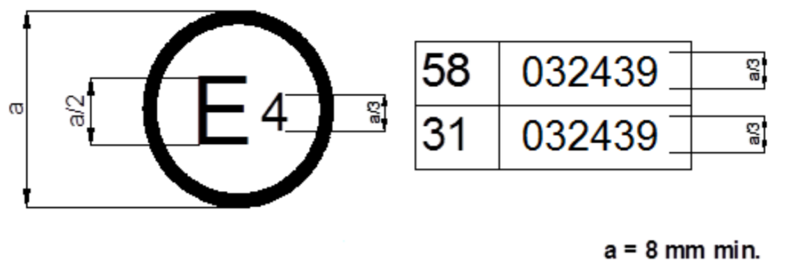
| A4 | The above approval mark affixed to a vehicle or to an RUPD shows that the vehicle type or RUPD type concerned has, with regard to the rear underrun protection in the event of a collision, been approved in the Netherlands (E 4) pursuant to UN Regulation No. 58 under approval number 032439. The first two digits of the approval number indicate that the approval was granted in accordance with the requirements of UN Regulation No. 58 as amended by the 03 series of amendments. | a0c0 |
| A4 |
Model B (see paragraphs 6.5., 15.5., 24.5. of this Regulation) |
a0c0 |
| A4 |
|
a0c0 |
| A4 | The above approval mark affixed to a vehicle shows that the vehicle type concerned has been approved in the Netherlands (E 4) pursuant to UN Regulations Nos. 58 and 31. [1] The approval numbers indicate that, at the dates when the respective approvals were given, UN Regulation No. 58 included the 03 series of amendments and UN Regulation No. 31 was still in its original form. | a0c0 |
|
A4 |
|
a0c0 |
| A5 |
|
a0c0 |
| A5 |
|
a0c0 |
| A5 1. | Test conditions for RUPDs | a0c0 |
| A5 1.1. | At the request of the manufacturer the test may be conducted either: | a0c0 |
| A5 1.1.1. | On a vehicle of the type for which RUPD is intended; in this case the conditions set out in paragraph 2. below shall be observed; or | a0c0 |
| A5 1.1.2. | On a part of the chassis of the vehicle type for which the RUPD is intended; this part shall be representative of the vehicle type(s) in question; or | a0c0 |
| A5 1.2. | In the case of paragraph 1.1.2., the parts used to connect the RUPD to part of the vehicle chassis shall be equivalent to those which are used to secure the RUPD when it is installed on the vehicle.The part of the chassis can be fixed on a test bench as shown in Figure 1, representing the minimum requirements to be fulfilled. The structures used as side rails shall be representative of the chassis of vehicles for which the underrun protection system is intended. | a0c0 |
| A5 | The distance of the foremost fixing point of the RUPD from the rigid test bench shall not be less than 500 mm. If a diagonal strut is used to support the RUPD, this distance shall be measured between the foremost fixing point of the strut to the side rail structures and the rigid test bench. | a0c0 |
| A5 | Figure 1 | a0c0 |
| A5 |

|
a0c0 |
| A5 1.3. | At the request of the manufacturer and with the consent of the Technical Service the test procedure described in paragraph 3. may be simulated by calculation. | a0c0 |
| A5 | The mathematical model shall be validated in comparison with the actual test conditions. To that effect, a physical test shall be conducted for the purposes of comparing the results obtained when using the mathematical model with the results of a physical test. Comparability of the test results shall be proven. A validation report shall be drafted by the manufacturer or by the technical service and submitted to the Type Approval Authority. | a0c0 |
| A5 | Any change made to the mathematical model or to the software likely to invalidate the validation report shall be brought to the attention of the Type Approval Authority which may require a new validation process to be conducted. | a0c0 |
| A5 1.4. | In the case of a RUPD where the cross-member does not have a vertical flat surface of at least 50 per cent of the minimum section height of the cross-member according to paragraph 7.1. or 25.5. of this Regulation at the height of the points of application of the test forces according to paragraph 16.1. or 25.1., the manufacturer shall supply the Technical Service with a device that allows the application of horizontal test loads on the crossmember with the test equipment used by the Technical Service. The device shall not modify the dimensional and mechanical characteristics of the RUPD or increase its resistance during test. The device shall neither be rigidly fixed to the RUPD nor to the test equipment. | a0c0 |
| A5 2. | Test conditions for vehicles | a0c0 |
| A5 2.1. | The vehicle shall be at rest on a level, flat, rigid and smooth surface. | a0c0 |
| A5 2.2. | The front wheels shall be in the straight-ahead position. | a0c0 |
| A5 2.3. | The tyres shall be inflated to the pressure recommended by the vehicle manufacturer. | a0c0 |
| A5 2.4. |
The vehicle may, if necessary to achieve the test forces required in paragraph 3.1. below, be restrained by any method, this method to be specified by the vehicle manufacturer. |
a0c0 |
| A5 2.5. | Vehicles equipped with hydropneumatic, hydraulic or pneumatic suspension or a device for automatic levelling according to load shall be tested with the suspension or device in the normal running condition specified by the manufacturer. | a0c0 |
| A5 3.1. |
The requirements of paragraphs 7.3. and 25.7. of this Regulation shall be verified by means of suitable test mandrels; the forces for tests prescribed in paragraphs 3.1.1. and 3.1.2. below shall be applied separately and consecutively, via a surface not more than 250 mm in height (but covering the maximum section height of the cross-member or RUP, the exact height shall be indicated by the manufacturer) and 200 mm wide, with a radius of curvature of 5 ± 1 mm at the vertical edges. The RUP shall offer adequate resistance to forces applied parallel to the longitudinal axis of the vehicle. The surface shall not be rigidly fixed to the RUPD or to the RUP and shall be articulated in all directions. The height above the ground of the centre of the surface shall be defined by the manufacturer within the lines that bound the device horizontally. When the test is carried out on a vehicle the height shall not, however, exceed the height as specified in paragraphs 16.1. and 16.2. or as specified in paragraphs 25.1. and 25.2. of this Regulation when the vehicle is unladen. The order in which the forces are applied may be specified by the manufacturer. |
a0c0 |
| A5 | The device used to distribute the test force over the stated flat surface shall be connected to the force actuator through a swivel joint. The arrangement of the force actuator, whether pulling or pushing, shall be arranged such that it does not add any stiffness or stability to the underrun protection system structure, i.e. it shall neither increase the instability threshold force nor decrease the maximum deflection of the underrun protection system. | a0c0 |
| A5 3.1.1. | A horizontal force of 180 kN or 85 per cent of the force generated by the maximum mass of the vehicle, whichever is the lesser, shall be applied consecutively to two points situated symmetrically about the centre line of the device or of the vehicle whichever is applicable at a minimum distance apart of 700 mm and a maximum of 1 m. The exact location of the points of application shall be specified by the manufacturer. | a0c0 |
| A5 | Notwithstanding the provision above for non-separate cab vehicles of category N2 with a maximum mass not exceeding 8 t, the horizontal forces may be reduced to 100 kN or 50 per cent. | a0c0 |
| A5 3.1.2. |
In the cases defined in paragraphs 1.1.1. and 1.1.2. of this annex a horizontal force of 100 kN or 50 per cent of the force generated by the maximum mass of the vehicle, whichever is the lesser, shall be applied consecutively to two points located 300 ± 25 mm from the longitudinal planes tangential to the outer edges of the wheels on the rear axle or of the RUPD, if it exceeds the width of the rear axle, and to a third point located on the line joining these two points, in the median vertical plane of the vehicle. |
a0c0 |
| A5 | Notwithstanding the provision above for non-separate cab vehicles of category N2 with a maximum mass not exceeding 8 t, the horizontal forces may be reduced to 50 kN or 25 per cent. | a0c0 |
| A5 3.1.3. | Upon request of the manufacturer, the force levels can be reduced to 80 per cent of the requirement given in paragraphs 3.1.1. to 3.1.2. for the vehicles listed in Annex 6. | a0c0 |
| A5 3.2. | Replacement force application points | a0c0 |
| A5 |
If any point defined under paragraph 3.1. is located within the interruption area of the underrun protection device as mentioned in paragraph 7.4. or 25.8. of this Regulation, the test forces shall be applied at replacement points located: |
a0c0 |
| A5 3.2.1. |
for the requirement under paragraph 3.1.1., on the horizontal centerline and within 50 mm of each vertical edge closest to the intended points of force application, as defined in that paragraph, and |
a0c0 |
| A5 3.2.2. |
for the requirement under paragraph 3.1.2., at the intersection of the horizontal and vertical centerlines of each element furthest from the vertical centerline of the device or of the vehicle, whichever is applicable. These points should be a maximum of 325 mm from the longitudinal planes tangential to the outer edges of the wheels on the rear axle. |
a0c0 |
| A6 |
|
a0c0 |
| A6 |
|
a0c0 |
| A6 1. | Specific types of vehicles | a0c0 |
| A6 1.1. | Vehicles with tipping-bodies; | a0c0 |
| A6 1.2. | Vehicles fitted with a platform lift at the rear. | a0c0 |
| A7 |
|
a0c0 |
| A7 |
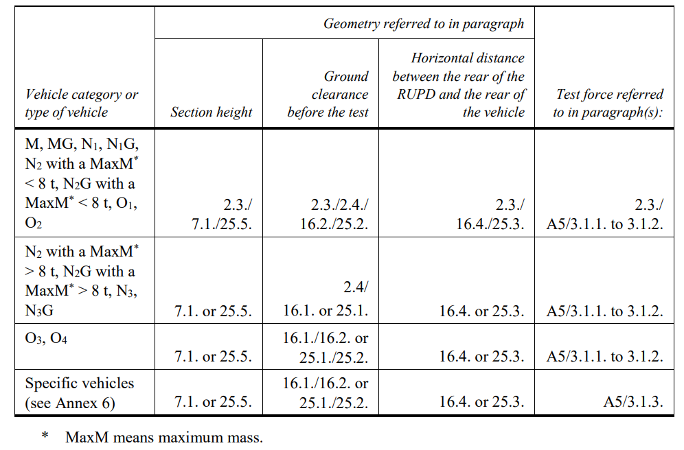
Requirements for different vehicle categories
|
a0c0 |
| A7 |
|
a1c0 |
| A7 | Note: A reference such as A5/3.1.1. in the table indicates the annex (Annex 5) and paragraph (3.1.1.) of that annex, where the relevant vehicle or requirement is described and specified. A reference such as 2.3. in the table indicates paragraph (2.3.) of this Regulation, where the relevant requirement is specified. | a0c0 |
| A7 |
Annex 8 |
a0c0 |
| A7 |
Aerodynamic devices |
a2c0 |
| A7 1. |
Purpose The purpose of this test is to verify whether the aerodynamic device in the event of a collision with the rear of the vehicle or the vehicle combination is compromising the rear underrun protection. |
a2c0 |
| A7 2. |
General specifications |
a2c0 |
| A7 2.1. |
The external surface of aerodynamic devices shall not exhibit, directed outwards, any pointed or sharp parts or any projections of such shape, dimensions, direction or hardness as to be likely to increase the risk or seriousness of bodily injury to a person hit by the external surface or brushing against it in the event of a collision. |
a2c0 |
| A7 2.2. |
The external surface of vehicles shall not exhibit, directed outwards, any part likely to catch on pedestrians, cyclists or motor cyclists. |
a2c0 |
| A7 2.3. |
Protruding parts of the external surface of an aerodynamic device shall not have a radius of curvature less than 2.5 mm. Those parts of the external surface of an aerodynamic device which are so located that, in their folded or retracted condition as well as when in operation, they cannot be contacted by a sphere 100 mm in diameter, may have a radius of curvature less than 2.5 mm. This requirement shall not apply to parts of the external surface which protrude less than 5 mm, but the outward facing angles of such parts shall be blunted, save where such parts protrude less than 1.5 mm. |
a2c0 |
| A7 2.4. |
Protruding parts of the external surface, made of a material of hardness not exceeding 60 shore A, may have a radius of curvature less than 2.5 mm. The hardness measurement shall be taken with the component as installed on the vehicle. Where it is impossible to carry out a hardness measurement by the Shore A procedure, comparable measurements shall be used for evaluation. |
a2c0 |
| A7 3. |
Test conditions for aerodynamic devices |
a2c0 |
| A7 3.1. |
At the request of the manufacturer the test may be conducted either: |
a2c0 |
| A7 3.1.1. |
On a vehicle of the type for which an aerodynamic device is intended; in this case the test conditions set out in paragraph 4. below shall be observed; or |
a2c0 |
| A7 3.1.2. |
On a part of the body of the vehicle type for which the aerodynamic device is intended; this part shall be representative of the vehicle type(s) in question; or |
a2c0 |
| A7 3.1.3. |
On a rigid wall. |
a2c0 |
| A7 3.2. |
In the case of paragraph 3.1.2. and 3.1.3., the parts used to connect the aerodynamic devices to a part of the vehicle body or to a rigid wall shall be equivalent to those which are used to secure the aerodynamic devices when it is installed on the vehicle. Every device shall be accompanied by installation and operating instructions giving sufficient information for any competent person to install it correctly. |
a2c0 |
| A7 3.3. |
At the request of the manufacturer the test procedure described in paragraph 5. may be simulated by calculation. |
a2c0 |
| A7 4. |
Test conditions for vehicles |
a2c0 |
| A7 4.1. |
The vehicle shall be at rest on a level, flat, rigid and smooth surface. |
a2c0 |
| A7 4.2. |
The front wheels shall be in the straight-ahead position. |
a2c0 |
| A7 4.3. |
The tyres shall be inflated to the pressure recommended by the vehicle manufacturer. |
a2c0 |
| A7 4.4. |
The vehicle is unladen. |
a2c0 |
| A7 4.5. |
The vehicle may, if necessary to achieve the test force required in paragraph 5.1.2. below, be restrained by any method. This method is to be specified by the vehicle manufacturer. |
a2c0 |
| A7 4.6. |
Vehicles equipped with hydropneumatic, hydraulic or pneumatic suspension or a device for automatic levelling according to load shall be tested with the suspension or device in the normal running condition specified by the manufacturer. |
a2c0 |
| A7 5. |
Test procedure |
a2c0 |
| A7 5.1. |
The aerodynamic device shall offer a certain level of deformation to forces applied parallel to the longitudinal axis of the vehicle. Alternatively, the device may also be folded or retracted under the influence of force. The test shall be verified by means of suitable test mandrels. The device used to distribute the test force over the stated flat surface shall be connected to the force actuator through a swivel joint. In cases of geometric incompatibilities, it is recommended to use an adaptor instead of a device with a flat surface. |
a2c0 |
| A7 5.1.1. |
A force shall be applied parallel to the longitudinal axis of the vehicle via a surface not more than 250 mm in height and 200 mm wide with a radius of curvature of 5 ± 1 mm at the vertical edges or an adaptor. The surface or adaptor shall not be rigidly fixed to the aerodynamic device and shall be articulated in all directions. When the test is carried out on a vehicle the height of the centre of the surface or adaptor shall be defined by the manufacturer in an area between the lowest edge of the aerodynamic device and a point no more than 2.0 meters above the ground in vehicle-mounted condition (see figure 1). This point is to be defined on a laden vehicle with the technically permissible maximum laden mass. |
a2c0 |
| A7 |
Figure 1
|
a2c0 |
| A7 |
Figure 2
|
a2c0 |
| A7 |
A horizontal force of maximum 4000 N ± 400 N shall be applied consecutively to two points situated symmetrically about the centre line of the vehicle or the centre line of the device on the rearmost outer edge of the aerodynamic device in completely unfolded or not retracted condition (see figure 3). The order in which the forces are applied may be specified by the manufacturer. |
a2c0 |
| A7 |
Figure 3 |
a2c0 |
| A7 |
|
a2c0 |
| A7 |
Requirements |
a2c0 |
| A7 6.1. |
The aerodynamic device shall be so fitted that during the application of the test forces as specified in paragraph 5.1.2 this aerodynamic device has at the point of application of forces an elastic and/or plastic deformation with a maximum remaining length of 200 mm in longitudinal direction of the vehicle. |
a2c0 |
| A7 6.2. |
Notwithstanding the provisions in paragraph 5.1., 5.1.1., 5.1.2. and 6.1. the application of forces shall not be conducted if the aerodynamic device is made of a material of hardness not exceeding 60 shore A in the area 1 regarding figure 4. Components (fastenings, hinges, actuators, springs, cables, lamps, etc.) used to install the aerodynamic device on the body of the vehicle or that are mounted on the aerodynamic device are exempted from these provisions. |
a2c0 |
| A7 |
Figure 4
|
a2c0 |
| A7 7. |
Marking |
a2c0 |
| A7 7.1. |
There shall be affixed to the aerodynamic device a clearly legible and indelible marking consisting of: |
a2c0 |
Regulation UN No. 58 (Rev.3)
Rear underrun protective devices (RUPDs)
Consolidated up to
Suppl.3 to 03
dated: 22.06.2022.png)
.png)
.png)
.png)
.png)