| ... | Regulation | a0c0 |
| ... | 1.Scope | a0c0 |
| ... | I.Devices for indirect vision | a0c0 |
| ... | 2.Definitions | a0c0 |
| ... | 3.Application for approval | a0c0 |
| ... | 4.Markings | a0c0 |
| ... | 5.Approval | a0c0 |
| ... | 6.Requirements | a0c0 |
| ... | 7.Modification of the type of device for indirect vision and extension of approval | a0c0 |
| ... | 8.Conformity of production | a0c0 |
| ... | 9.Penalties for non conformity of production | a0c0 |
| ... | 10.Production definitively discontinued | a0c0 |
| ... | 11.Names and addresses of Technical Services responsible for conducting approval tests and of Type Approval Authorities | a0c0 |
| ... | II.Installation of devices for indirect vision | a0c0 |
| ... | 12.Definitions | a0c0 |
| ... | 13.Application for approval | a0c0 |
| ... | 14.Approval | a0c0 |
| ... | 15.Requirements | a0c0 |
| ... | 16.Modifications of the vehicle type and extension of approval | a0c0 |
| ... | 17.Conformity of production | a0c0 |
| ... | 18.Penalties for non conformity of production | a0c0 |
| ... | 19.Production definitively discontinued | a0c0 |
| ... | 20.Names and addresses of Technical Services responsible for conducting approval tests, and of Type Approval Authorities | a0c0 |
| ... | 21.Transitional provisions | a0c0 |
| ... | Annexes | a0c0 |
| ... | 1.Information document for type approval of a device for indirect vision | a0c0 |
| ... | 2.Information document for type approval of vehicle with respect to the installation of devices for indirect vision | a0c0 |
| ... | 3.Communication concerning the approval or refusal or extension or withdrawal of approval or production definitively discontinued of a type of device for indirect vision, pursuant to Regulation No. 46 | a0c0 |
| ... | 4.Communication concerning the approval or refusal or extension or withdrawal of approval or production definitively discontinued of a type of vehicle with regard to the mounting of devices for indirect vision, pursuant to Regulation No. 46 | a0c0 |
| ... | Appendix | a0c0 |
| ... | 5.Arrangement of approval mark for a device for indirect vision | a0c0 |
| ... | 6.Test method for determining reflectivity | a0c0 |
| ... | 7.Procedure for determining the radius of curvature "r" of the reflecting surface of a mirror | a0c0 |
| ... | 8.Procedure for determining the "H" point and the actual torso angle for seating positions in motor vehicles | a0c0 |
| ... | Appendix 1 - Description of the three-dimensional "H" point machine (3-D H machine) | a0c0 |
| ... | Appendix 2 - Three-dimensional reference system | a0c0 |
| ... | Appendix 3 - Reference data concerning seating positions | a0c0 |
| ... | 9.(Reserved) | a0c0 |
| ... | 10.Calculation of the detection distance for CMS of Classes V and VI | a0c0 |
| ... | 11.Determination of the displayed object size for CMS of Classes V and VI | a0c0 |
| ... | 12.Test methods and safety provisions for CMS of Classes I to IV | a0c0 |
| 1. |
|
a0c0 |
| 1.1. | This Regulation applies: | a0c0 |
| ... | a) To compulsory and optional devices for indirect vision, set out in the table under paragraph 15.2.1.1.1. of this Regulation for vehicles of category M and N and to compulsory and optional devices for indirect vision mentioned in paragraphs 15.2.1.1.3. and 15.2.1.1.4. of this Regulation for vehicles of category L[1] with bodywork at least partly enclosing the driver; | a0c0 |
| ... | b) To the installation of devices for indirect visions on vehicles of categories M and N and on vehicles of category L1 with bodywork at least partly enclosing the driver. | a0c0 |
| 1.2 | This Regulation does not apply to devices other than those prescribed under paragraph 1.1.(a) and their installation, for observing the vision area(s) immediately adjacent to the front and/or the passenger's side of vehicles of category M1, M2, M3, N1 and N2 ≤ 7.5 t. | a0c0 |
| I. |
|
a0c0 |
| 2. |
|
a0c0 |
| ... | For the purpose of this Regulation: | a0c0 |
| 2.1. | "Devices for indirect vision" means devices intended to give a clear view of the rear, side or front of the vehicle within the fields of vision defined in paragraph 15.2.4. These can be conventional mirrors, camera-monitors or other devices able to present information about the indirect field of vision to the driver. | a0c0 |
| 2.1.1. | "Mirror" means any device, excluding devices such as periscopes, intended to give a clear view to the rear, side or front of the vehicle within the fields of vision defined in paragraph 15.2.4. by means of a reflective surface. | a0c0 |
| 2.1.1.1. | "Interior mirror" means a device as defined in paragraph 2.1.1. above, which can be fitted in the passenger compartment of a vehicle. | a0c0 |
| 2.1.1.2. | "Exterior mirror" means a device as defined in paragraph 2.1.1. above, which can be mounted on the external surface of a vehicle. | a0c0 |
| 2.1.1.3. | "Surveillance mirror" means a mirror other than the ones defined in paragraph 2.1.1. above which can be fitted to the inside or outside of the vehicle in order to provide fields of vision other than those specified in paragraph 15.2.4. of this Regulation. | a0c0 |
| 2.1.1.4. | "r" means the average of the radii of curvature measured over the reflecting surface, in accordance with the method described in Annex 7. | a0c0 |
|
|
|
a0c0 |
| 2.1.1.5. | "The principal radii of curvature at one point on the reflecting surface (ri)" means the values obtained with the apparatus defined in Annex 7, measured on the arc of the reflecting surface passing through the centre of this surface parallel to the segment b, as defined in paragraph 6.1.2.1.2.1. of this Regulation and on the arc perpendicular to this segment. | a0c0 |
| 2.1.1.6. | "The radius of curvature at one point on the reflecting surface (rp)" means the arithmetical average of the principal radii of curvature ri and , i.e.: | a0c0 |
| ... |

|
a0c0 |
| 2.1.1.7. |
"Spherical surface" means a convex surface, which has, in both horizontal and vertical direction, measured radii of curvature compliant with the provisions given in paragraphs 6.1.2.2.2 and 6.1.2.2.4. |
a7c0 |
| 2.1.1.8. |
"Aspherical surface" means a convex surface, which may have variable radii of curvature both in the horizontal and vertical direction. |
a7c0 |
| 2.1.1.9. |
"Aspherical mirror" means a mirror composed of a spherical and an aspherical part, defined in 2.1.1.7 and 2.1.1.8 respectively, in which the transition of the reflecting surface from the spherical to the aspherical part has to be marked. |
a7c0 |
| ... |
|
a7c0 |
| ... | Where: | a0c0 |
| ... | R: nominal radius in the spherical part | a0c0 |
| ... | k: constant for the change of curvature | a0c0 |
| ... | a: constant for the spherical size of the spherical primary calotte | a0c0 |
| 2.1.1.10. | "Centre of the reflecting surface"means the centre of the visible area of the reflecting surface. | a0c0 |
| 2.1.1.11. | "The radius of curvature of the constituent parts of the mirror"means the radius "c" of the arc of the circle which most closely approximates to the curved form of the part in question. | a0c0 |
| 2.1.2. | "Camera-monitor system (CMS)"means a device for indirect vision as defined in paragraph 2.1., where the field of vision is obtained by means of a camera-monitor combination as defined in paragraphs 2.1.2.1. and 2.1.2.2. below. | a0c0 |
| 2.1.2.1. | "Camera"means a device that renders an image of the outside world and then converts this image into a signal (e.g. video signal). | a0c0 |
| 2.1.2.2. | "Monitor"means a device that converts a signal into images that are rendered into the visual spectrum. | a0c0 |
| 2.1.3. | "Other devices for indirect vision"means devices as defined in paragraph 2.1. above, where the field of vision is not obtained by means of a mirror or a camera-monitor device. | a0c0 |
| 2.1.4. | "Vision support system"means a system to enable the driver to detect and/or see objects in the area adjacent to the vehicle | a0c0 |
| 2.1.5. | "Luminance contrast"means the brightness ratio between an object and its immediate background/surrounding that allows the object to be distinguished from its background/surroundings. The definition is in accordance with the definition given in ISO 9241-302:2008. | a0c0 |
| 2.1.6. | "Resolution"means the smallest detail that can be discerned with a perceptual system, i.e. perceived as separate from the larger whole. The resolution of the human eye is indicated as "visual acuity". | a0c0 |
| 2.1.7. | "Critical object"means a cylindrical object with a height of 0.50 m and a diameter of 0.30 m. | a0c0 |
| 2.1.8. | "Critical perception"means the level of perception that can just be obtained under critical conditions via the viewing system used. This corresponds to the situation in which the representative scale of the critical object is multiple times larger than the smallest detail that can be perceived via the viewing system. | a0c0 |
| 2.1.9. | "Field of vision"means the section of the tri-dimensional space which is monitored with the help of a device for indirect vision. Unless otherwise stated, this is based on the view on ground level offered by a device and/or devices other than mirrors. This may be limited by the relevant detection distance corresponding to the critical object. | a0c0 |
| 2.1.10. | "Detection distance"means the distance measured from the centre of the lens of the camera to the point at which a critical object can just be perceived (as defined by the critical perception). | a0c0 |
| 2.1.11. | "Visual spectrum"means light with a wavelength within the range of the perceptual limits of the human eyes: 380 - 780 nm. | a0c0 |
| 2.1.12. | "Smear"is a bright line displayed on the monitor while sun light or light from other bright light sources is directly hitting into the lens of the camera. | a0c0 |
| 2.1.13. | "Mirror and CMS dual function system"means a CMS of Class I in which a monitor complying with this regulation is placed behind a semi-transparent mirror complying with this regulation. The monitor is visible in the CMS mode. | a0c0 |
| 2.2. | "Type of device for indirect vision"means devices that do not differ on the following essential characteristics: | a0c0 |
| ... | a) Design of the device inclusive, if pertinent, the attachment to the bodywork; | a0c0 |
| ... | b) In the case of mirrors, the class, the shape, the dimensions and radius of curvature of the mirror's reflecting surface; | a0c0 |
| ... | c) In the case of camera-monitor systems, the class, the field of view, the magnification and resolution. | a0c0 |
| 2.3. | "Surveillance camera-monitor-recording device"means a camera and either a monitor or recording equipment other than the camera-monitor system defined in paragraph 2.1.2. above which can be fitted to the inside or outside of the vehicle in order to provide fields of vision other than those specified in paragraph 15.2.4. of this Regulation or to provide a security system within or around the vehicle. | a0c0 |
| 2.4. | "Class of device for indirect vision"means all devices having one or more common characteristics or functions. They are classified as follows: | a0c0 |
| 2.4.1. | Class I: "Rear-view device", giving the field of vision defined in paragraph 15.2.4.1. | a0c0 |
| 2.4.2. | Class II and III: "Main rear-view device", giving the fields of vision defined in paragraphs 15.2.4.2. and 15.2.4.3. | a0c0 |
| 2.4.3. | Class IV: "Wide-angle view device", giving the field of vision defined in paragraph 15.2.4.4. | a0c0 |
| 2.4.4. | Class V: "Close-proximity view device", giving the field of vision defined in paragraph 15.2.4.5. | a0c0 |
| 2.4.5. | Class VI: "Front-view device", giving the field of vision defined in paragraph 15.2.4.6. | a0c0 |
| 2.4.6. | Class VII: Main rear-view mirrors intended for L category vehicles with bodywork giving the field of vision defined in paragraph 15.2.4.7. | a0c0 |
| 2.5. | "Point light source detection factor - PLSDF"means the level of distinctness of a pair of point light sources, based on luminance intensities and horizontal and vertical dimension of the rendition on the monitor. | a0c0 |
| 2.6. | "Point light source contrast factor - PLSCF"means the level of distinctness of a pair of point light sources, based on luminance differences between the maximum luminance of the luminance profile LH,max and the minimum luminance of the luminance profile LH,min in the horizontal direction (see Figure 3 of Annex 12). | a0c0 |
| 3. |
|
a0c0 |
| 3.1. | The application for approval of a type of device for indirect vision shall be submitted by the holder of the trade name or mark or by his duly accredited representative. | a0c0 |
| 3.2. | A model of information document is shown in Annex 1. | a0c0 |
| 3.3. | For each type of device for indirect vision the application shall be accompanied by three samples of the parts. | a0c0 |
| 3.4. | The CMS shall be provided by the applicant with the following documents: | a0c0 |
| ... | a) Technical specification of the CMS; and | a0c0 |
| ... | b) Operator's manual. | a0c0 |
| 4. |
|
a0c0 |
| 4.1. | The samples of devices for indirect vision submitted for approval shall bear the trade name or mark of the manufacturer; this marking shall be clearly legible and be indelible. | a0c0 |
| 4.2. | Every device for indirect vision shall possess, on at least one of the main components a space large enough to accommodate the approval mark, which shall be legible; this space shall be shown on the drawings referred to in Annex 1. The approval mark shall also be legible when the device is mounted on the vehicle with exception of camera-monitor devices as defined in paragraph 2.1.2. Other components of the device shall bear a means of identification. In the case of limited space for the approval mark(s), other means of identification that link it to the approval mark shall be provided. | a0c0 |
| 5. |
|
a0c0 |
| 5.1. | If the samples submitted for approval meet the requirements of paragraph 6. of this Regulation, approval of the pertinent type of device for indirect vision shall be granted. | a0c0 |
| 5.2. | An approval number shall be assigned to each type approved. Its first two digits (at present 04) shall indicate the series of amendments incorporating the most recent major technical amendments made to the Regulation at the time of issue of the approval. The same Contracting Party shall not assign the same number to another type of device for indirect vision. | a0c0 |
| 5.3. | Notice of approval or of refusal or of extension or withdrawal of approval or of production definitively discontinued of a type of device for indirect vision pursuant to this Regulation shall be communicated to the Parties to the Agreement which apply this Regulation by means of a form conforming to the model in Annex 3 to this Regulation. | a0c0 |
| 5.4. | There shall be affixed, on at least one of the main components, conspicuously and in the space referred to in paragraph 4.2. above, to every device for indirect vision, conforming to a type approved under this Regulation, in addition to the mark prescribed in paragraph 4.1. above, an international approval mark consisting of: | a0c0 |
| 5.4.1. | A circle surrounding the letter "E" followed by the distinguishing number of the country which has granted approval[2]; | a0c0 |
| 5.4.2. | An approval number; | a0c0 |
| 5.4.3. | Additional symbol(s) I or II or/and III or/and IV or/and V or/and VI or/and VII, specifying the class to which the type of device for indirect vision belongs. The additional symbol shall be placed in any convenient position in the vicinity of the circle containing the letter "E". | a0c0 |
| 5.5. | The approval mark and the additional symbol(s) shall be clearly legible and be indelible. | a0c0 |
| 5.6. | Annex 5 to this Regulation gives an example of the arrangement of the aforesaid approval mark and additional symbol. | a0c0 |
|
|
|
a0c0 |
| ... |
|
a0c0 |
| 6.1. | Mirrors | a0c0 |
| 6.1.1. | General specifications | a0c0 |
| 6.1.1.1. | All mirrors shall be adjustable. | a0c0 |
| 6.1.1.2. | a) Rear-view mirrors (Classes II to VII) | a0c0 |
| ... | The edge of the reflecting surface shall be enclosed in a protective housing (holder, etc.) which, on its perimeter, shall have a value "c" greater than or equal to 2.5 mm at all points and in all directions. If the reflecting surface projects beyond the protective housing, the radius of curvature "c" on the edge of the projecting part shall be not less than 2.5 mm and the reflecting surface shall return into the protective housing under a force of 50 N applied to the point of greatest projection, relative to the protective housing, in a horizontal direction, approximately parallel to the longitudinal median plane of the vehicle. | a0c0 |
| ... | b) Rear-view mirrors (Class I) | a0c0 |
| ... | In cases, where the edge of the reflecting surface is enclosed in a protective housing (holder, etc.), the radius of curvature "c" on its perimeter shall be not less than 2.5 mm at all points and in all directions. In cases, where the edge of the reflecting surface projects beyond the protective housing, this requirement shall apply to the edge of the projecting part. | a0c0 |
| 6.1.1.3. | When the mirror is mounted on a plane surface, all parts, irrespective of the adjustment position of the device, including those parts remaining attached to the support after the test provided for in paragraph 6.3.2. below, which are in potential, static contact with a sphere either 165 mm in diameter in the case of a Class I mirror or 100 mm in diameter in the case of a Class II to VII mirror, shall have a radius of curvature 'c' of not less than 2.5 mm. | a0c0 |
| 6.1.1.4. | The requirements in paragraphs 6.1.1.2. and 6.1.1.3. above shall not apply to parts of the external surface which protrude less than 5 mm, but the outward facing angles of such parts shall be blunted, save where such parts protrude less than 1.5 mm. For determining the dimension of the projection, the following method shall apply: | a0c0 |
| 6.1.1.4.1. | The dimension of the projection of a component which is mounted on a convex surface may be determined either directly or by reference to a drawing of an appropriate section of this component in its installed condition. | a0c0 |
| 6.1.1.4.2. | If the dimension of the projection of a component which is mounted on a surface other than convex cannot be determined by simple measurement, it shall be determined by the maximum variation of the distance of the centre of a 100 mm diameter sphere from the nominal line of the panel when the sphere is moved over and is in constant contact with that component. Figure 1 shows an example of the use of this procedure. | a0c0 |
| ... | Figure 1 | a0c0 |
| ... | Example for the measurement by maximum variation | a0c0 |
| ... |
|
a0c0 |
| 6.1.1.5. | Edges of fixing holes or recesses of which the diameter or longest diagonal is less than 12 mm are exempt from the radius requirements of paragraph 6.1.1.3. above provided that they are blunted. | a0c0 |
| 6.1.1.6. | The device for the attachment of mirrors to the vehicle shall be so designed that a cylinder with a 70 mm radius (50 mm in the case of an L-category vehicle), having as its axis the axis, or one of the axes, of pivot or rotation which ensures deflection of the mirror in the direction of impact concerned, passes through at least part of the surface to which the device is attached. | a0c0 |
| 6.1.1.7. | The parts of Classes II to VII mirrors referred to in paragraphs 6.1.1.2. and 6.1.1.3. above which are made of a material with a Shore A hardness not exceeding 60 are exempt from the relevant provisions. | a0c0 |
| 6.1.1.8. | In the case of those parts of Class I mirrors which are made of a material with a Shore A hardness of less than 50 and which are mounted on a rigid support, the requirements of paragraphs 6.1.1.2. and 6.1.1.3. above shall only apply to the support. | a0c0 |
| 6.1.2. | Special specifications | a0c0 |
| 6.1.2.1. | Dimensions | a0c0 |
| 6.1.2.1.1. | Rear-view mirrors (Class I) | a0c0 |
| ... | The dimensions of the reflecting surface shall be such that it is possible to inscribe thereon a rectangle one side of which is 40 mm and the other 'a' mm in length, where | a0c0 |
| ... |

|
a0c0 |
| ... | and "r" is the radius of curvature. | a0c0 |
| 6.1.2.1.2. | Main rear-view mirrors (Classes II and III) | a0c0 |
| 6.1.2.1.2.1. | The dimensions of the reflecting surface shall be such that it is possible to inscribe therein: | a0c0 |
| ... | a) A rectangle 40 mm high the base length of which, measured in millimetres, has the value "a"; | a0c0 |
| ... | b) A segment which is parallel to the height of the rectangle and the length of which, expressed in millimetres, has the value "b". | a0c0 |
| 6.1.2.1.2.2. | The minimum values of "a" and "b" are given in the table below: | a0c0 |
| ... |
|
a0c0 |
| 6.1.2.1.3. | "Wide-angle" view mirrors (Class IV) | a0c0 |
| ... | The contours of the reflecting surface shall be of simple geometric form and its dimensions such that it provides, if necessary in conjunction with a Class II exterior mirror, the field of vision specified in paragraph 15.2.4.4. of this Regulation. | a0c0 |
| 6.1.2.1.4. | "Close-proximity" view mirrors (Class V) | a0c0 |
| ... | The contours of the reflecting surface shall be of simple geometric form and its dimensions such that the mirror provides the field of vision specified in paragraph 15.2.4.5. of this Regulation. | a0c0 |
| 6.1.2.1.5. | Front-view mirrors (Class VI) | a0c0 |
| ... | The contours of the reflecting surface shall be of simple geometric form and its dimensions such that the mirror provides the field of vision specified in paragraph 15.2.4.6. of this Regulation. | a0c0 |
| 6.1.2.1.6. | Mirrors for category L vehicles with bodywork (Class VII) | a0c0 |
| 6.1.2.1.6.1. | "Main" rear-view mirrors (Class VII) | a0c0 |
| ... | The minimum dimensions of the reflecting surface shall be such that: | a0c0 |
| ... | a) Its area shall not be less than 6,900 mm2; | a0c0 |
| ... | b) The diameter of circular mirrors shall not be less than 94 mm; | a0c0 |
| ... | c) Where rear-view mirrors are not circular, their dimensions shall enable a 78 mm-diameter circle to be prescribed on their reflecting surface. | a0c0 |
| ... | The maximum dimensions of the reflecting surface shall be such that: | a0c0 |
| ... | a) The diameter of any circular rear-view mirror shall not be greater than 150 mm; | a0c0 |
| ... | b) The reflecting surface of any non-circular rear-view mirror shall lie within a rectangle measuring 120 mm x 200 mm. | a0c0 |
| 6.1.2.2. | Reflecting surface and coefficients of reflection | a0c0 |
| 6.1.2.2.1. |
The reflecting surface of a mirror shall be either flat or [DEL] convex. Exterior mirrors may be equipped with an additional aspherical part provided that the main mirror fulfils the requirements of the indirect field of vision. |
a7c0 |
| 6.1.2.2.2. | Differences between the radii of curvature of mirrors | a0c0 |
| 6.1.2.2.2.1. | The difference between ri or r'i, and rp at each reference point shall not exceed 0.15 r. | a0c0 |
| 6.1.2.2.2.2. | The difference between any of the radii of curvature (rp1, rp2, and rp3) and r shall not exceed 0.15 r. | a0c0 |
| 6.1.2.2.2.3. | When r is not less than 3,000 mm, the value of 0.15 r quoted in paragraphs 6.1.2.2.2.1. and 6.1.2.2.2.2. above is replaced by 0.25 r. | a0c0 |
| 6.1.2.2.3. | Requirements for aspherical parts of mirrors | a0c0 |
| 6.1.2.2.3.1. | Aspherical mirrors shall be of sufficient size and shape to provide useful information to the driver. This normally means a minimum width of 30 mm at some point. | a0c0 |
| 6.1.2.2.3.2. | The radius of curvature ri of the aspherical part shall not be less than 150 mm. | a0c0 |
| 6.1.2.2.4. | Value of "r" for spherical mirrors shall not be less than: | a0c0 |
| 6.1.2.2.4.1. | 1,200 mm for rear-view mirrors (Class I); | a0c0 |
| 6.1.2.2.4.2. | 1,200 mm for Class II and III main rear-view mirrors; | a0c0 |
| 6.1.2.2.4.3. | 300 mm for "wide-angle" mirrors (Class IV) and "close-proximity" mirrors (Class V); | a0c0 |
| 6.1.2.2.4.4. | 200 mm for front mirrors (Class VI). | a0c0 |
| 6.1.2.2.4.5. | 1,000 mm or more than 1,500 mm for Class VII main rear-view mirrors. | a0c0 |
| 6.1.2.2.5. | The value of the normal coefficient of reflection, as determined according to the method described in Annex 6, shall be not less than 40 per cent. | a0c0 |
| ... | In the case of reflecting surfaces with a changeable degree of reflection, the "day" position shall allow the colours of the signals used for road traffic to be recognized. The value of the normal coefficient of reflection in the "night" position shall be not less than 4 per cent. | a0c0 |
| 6.1.2.2.6. | The reflecting surface shall retain the characteristics laid down in paragraph 6.1.2.2.5. above in spite of prolonged exposure to adverse weather conditions in normal use. | a0c0 |
| 6.2. | Devices for indirect vision other than mirrors | a0c0 |
| 6.2.1. | General requirements | a0c0 |
| 6.2.1.1. |
If adjustment by the user is needed, the device for indirect vision shall be adjustable without the use of tools. |
a0c0 |
| 6.2.1.2. |
If a device for indirect vision can only render the total prescribed field of vision by scanning the field of vision, the total process of scanning, rendering and reset to its initial position together shall not take more than |
a2c0 |
| 6.2.1.3. | The effectiveness of the CMS of Classes I to IV shall not be adversely affected by magnetic or electrical fields. This shall be demonstrated by compliance with the technical requirements and transitional provisions of Regulation No. 10, 04 series of amendments or any later series of amendements. | a0c0 |
| 6.2.2. | Camera-monitor systems | a0c0 |
| ... | The requirements of paragraph 6.2.2.1. shall be considered to be satisfied in the case of monitors of a vehicle that fulfills the provisions of Regulation No. 21. | a0c0 |
| 6.2.2.1. | General requirements | a0c0 |
| 6.2.2.1.1. | When the devices of the camera-monitor system are mounted in the position recommended by the manufacturer for normal driving, all parts, irrespective of the adjustment position of the device which are in potential, static contact with a sphere either 165 mm in diameter in the case of a CMS or parts of CMS installed inside the vehicle or 100 mm in diameter in the case of a CMS or parts of CMS installed outside the vehicle, shall have a radius of curvature "c" of not less than 2.5 mm. | a0c0 |
| 6.2.2.1.2. | Edges of fixing holes or recesses of which the diameter or longest diagonal is less than 12 mm are exempt from the radius requirements of paragraph 6.2.2.1.1. above provided that they are blunted. | a0c0 |
| 6.2.2.1.3. | For parts of the camera and the monitor which are made of a material with a Shore A hardness of less than 60 and which are mounted on a rigid support, the requirements of paragraph 6.2.2.1.1. above shall only apply to the support. | a0c0 |
| 6.2.2.2. | Functional requirements for camera-monitor devices of Classes V and VI | a0c0 |
| 6.2.2.2.1. | The camera shall function well in conditions in which sunlight falls on the camera. The saturated area, defined as the area in which the luminance contrast ratio (C=Lw/Lb) of a high contrast pattern falls below 2.0, shall not cover more than 15 per cent of the displayed image under the conditions of paragraphs 6.2.2.2.1.1. to 6.2.2.2.1.4. below. | a0c0 |
| ... | In the case the camera system shows dynamical changes in the blooming area during the test the maximum blooming area shall fulfill the requirements. | a0c0 |
| 6.2.2.2.1.1. | A black and white test pattern, having a minimum contrast ratio of 20 shall be positioned in front of the camera. | a0c0 |
| ... | The test pattern shall be evenly illuminated at an illumination of 3,000 ± 300 lx. | a0c0 |
| ... | The test pattern shall be medium gray on average and cover the complete area viewed by the camera; the camera shall view no other objects than the test pattern. | a0c0 |
| 6.2.2.2.1.2. | The camera shall be hit by a (simulated sun) light of 40 klx, spanning an angle between 0.6 and 0.9° with an elevation angle of 10° (directly or indirectly via a mirror) removed from the optical axis of the sensor. | a0c0 |
| ... | The light source shall: | a0c0 |
| ... | a) Have a spectrum D65 with a tolerance of ± 1,500 K; | a0c0 |
| ... | b) Be homogeneous in space and time within a tolerance of 2 klx. | a0c0 |
| ... | The emission of the light source in infrared shall be negligible. | a0c0 |
| 6.2.2.2.1.3. | There shall be no ambient illumination of the monitor during the test. | a0c0 |
| 6.2.2.2.1.4. | An example of the set-up is given in the Figure A below. | a0c0 |
| ... | Figure A | a0c0 |
| ... | Diagram of the blooming measurement set-up | a0c0 |
| ... |

|
a0c0 |
| 6.2.2.2.2. | The monitor shall render a minimum contrast under various light conditions as specified by ISO 15008:2003. | a0c0 |
| 6.2.2.2.3. | It shall be possible to adjust the average luminance of the monitor either manually or automatically to the ambient conditions. | a0c0 |
| 6.2.2.2.4. | The measurements for the luminance contrast of the monitor shall be carried out according to ISO 15008:2009. | a0c0 |
| 6.2.2.3. | Functional requirements for camera-monitor devices of Classes I to IV (see Annex 12). | a0c0 |
| ... | Unless otherwise specified in this Regulation, the definitions and symbols used in paragraph 6.2.2.3. are in accordance with ISO 16505:2015, Chapters 3 and 4. | a0c0 |
| ... | Unless otherwise specified in this Regulation, the requirements given in paragraph 6.2.2.3. shall be verified according to the test procedures given in ISO 16505:2015, Chapter 7, where available. | a0c0 |
| 6.2.2.3.1. | Luminance adjustment | a0c0 |
| ... | It shall be possible to adjust the average luminance of the monitor either manually or automatically to the ambient conditions. | a0c0 |
| 6.2.2.3.2. | Operating readiness (System availability) | a0c0 |
| ... | If the system is not operational (e.g. CMS failure), it shall be indicated to the driver by i.e. warning indication, display information, absence of status indicator. The operator's manual shall explain the information indicated. | a0c0 |
| 6.2.2.3.3. | Image quality | a0c0 |
| 6.2.2.3.3.1. | Monitor isotropy | a0c0 |
| ... | The monitor shall conform to optical requirements over the range of viewing directions that is specified in the following paragraphs. | a0c0 |
| 6.2.2.3.3.1.1. | Directional uniformity | a0c0 |
| ... | When driven by an artificial 70 per cent grey-scale image, the deviation of the monitor luminance from the luminance white level with specific viewing direction (θ, φ) = (θmonitor/D, φ monitor/D) shall be such that the ratio relative to the luminance white level for the same specific viewing direction L(θmonitor/D, φ monitor/D) does not exceed 35 per cent of the luminance white level for the monitor standard isotropy range and shall not exceed 50 per cent of the luminance white level for the monitor extended isotropy range. | a0c0 |
| ... | For the standard isotropy range: | a0c0 |
| ... |

|
a0c0 |
| ... | Table 2 | a0c0 |
| ... | Measurement directions for extended isotropy range | a0c0 |
| ... |

|
a0c0 |
| ... | Table 3 | a0c0 |
| ... | Measurement points for the lateral uniformity | a0c0 |
| ... |

|
a0c0 |
| 6.2.2.3.3.2. | Luminance and contrast rendering | a0c0 |
| ... | For luminance and contrast rendering the following requirements shall apply: | a0c0 |
| ... | a) The minimum luminance contrast at the monitor (including any screen protector) reproducing a high contrast pattern shall be: | a0c0 |
| ... | i) For direct sunlight condition: 2:1; | a0c0 |
| ... | ii) For day condition with diffuse ambient light: 3:1; | a0c0 |
| ... | iii) For sunset condition: 2:1; | a0c0 |
| ... | iv) For night condition: 10:1 except in the case of Mirror and CMS dual function system of class I: 5:1. | a0c0 |
| ... | b) The night condition for the camera's field of view is replicated in a dark environment such that the maximum illuminance on the objects to be measured shall not exceed 2.0 lx; | a0c0 |
| ... | c) The background luminance of the monitor shall be limited under the night condition. The maximum background luminance under the night condition shall be less than 2.0 cd/m2; | a0c0 |
| ... | d) The instructions for use shall contain a note that sunlight or light from other intense light source upon the monitor reduces the luminance contrast which may require the driver to be particularly alert and attentive. | a0c0 |
| 6.2.2.3.3.2.1. | Day condition with diffuse sky-light exposure test | a0c0 |
| ... | For the day condition with diffuse sky-light exposure, the test method given in ISO 16505:2015, subclause 7.8.2., Test 2 shall be applied, but a value of 4,000 to 4,200 cd/m2 for luminance diffuse illuminator shall be used. | a0c0 |
| ... | At the request of the manufacturer, the value for luminance diffuse illuminator may be determined by using the diagram of figure below. | a0c0 |
| ... |
|
a0c0 |
| ... | Ratio of projected area vs. luminance of the diffuse illuminator | a0c0 |
| ... | Procedure for determining the ration of the projected area leaving the vehicle: | a0c0 |
| ... | a) Determine the projected area in the vehicle that represents the mirror reflected direction from the monitor extended isotropy range. | a0c0 |
| ... | b) Evaluation shall be made in the centre of the monitor defined size, under consideration of the monitor design viewing direction (see figure below). | a0c0 |
| ... |
|
a0c0 |
| ... | This projected area represents the 100 per cent of the surface to be considered. | a0c0 |
| ... | Based on virtual testing, evaluate the ratio of the projected area that leaves the vehicle openings (e.g. through a side door window, rear window or sunroof; however, for example a sunroof having an opaque shutter shall not be considered an opening). | a0c0 |
| ... | Case when the orientation of the mirror and CMS dual function system of Class I is adjustable: | a0c0 |
| ... | Based on virtual testing, if the applicant demonstrates that the Mirror and CMS dual function system of Class I adjustment range permits a driver to avoid any incident specular light from the vehicle opening while a driver's eye is within any fixed position of the standard isotropy range, then the value for luminance diffuse illuminator shall be the one of ISO 16505:2015 subclause 7.8.2., Test 2: 1,300 to 1,500 cd/m2. | a0c0 |
| 6.2.2.3.3.3. | Grey scale rendering | a0c0 |
| ... | A CMS shall have a sufficient grey scale rendering. CMS shall display a tonal range of at least eight distinguishable different grey tonal steps on the monitor. | a0c0 |
| ... | For the grey scale rendering, the test method of paragraph 1.4. of Annex 12 shall be applied. | a0c0 |
| 6.2.2.3.3.4. | Colour rendering | a0c0 |
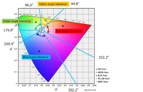
| ... | For colour rendering, the hue angle of reproduced colour of the chart patches on the monitor shall satisfy the following requirements. The colour coordinates are described based in the CIE 1976 uniform colour space: | a0c0 |
| ... | a) Red colour coordinates shall not exceed the range of (0°, 44.8°) or (332.2°, 360°); | a0c0 |
| ... | b) Green colour coordinates shall not exceed the range of (96.6°, 179.9°); | a0c0 |
| ... | c) Blue colour coordinates shall not exceed the range of (209.9°, 302.2°); | a0c0 |
| ... | d) Yellow colour coordinates shall not exceed the range of (44.8°, 96.6°); | a0c0 |
| ... | e) To distinguish from the white colour, define distance from white as Ri ≥ 0.02, where Ri is the chromatic distance of each colour patch (i = Red, Green, Blue, Yellow), relative to white (i = White). | a0c0 |
| ... | Figure B shows an illustrative tolerance range described on CIE 1976 uniform colour space. | a0c0 |
| ... | Figure B | a0c0 |
| ... |
|
a0c0 |
| ... | Amber, blue and red light signals shall be distinguishable from each other. | a0c0 |
| 6.2.2.3.3.5. | Artefacts | a0c0 |
| ... | The operator's manual shall refer to possible artefacts and their impact on the partial occlusion of the field of view and of the objects which may require the driver to be particularly alert and attentive. | a0c0 |
| 6.2.2.3.3.5.1. | Smear | a0c0 |
| ... | Smear shall be transparent and not be more than 10 per cent of the maximum luminance value of the displayed glare source luminance level, which causes smear effect. | a0c0 |
| 6.2.2.3.3.5.2. | Blooming and lens flare | a0c0 |
| ... | The total area of disturbing blooming and lens flare areas shall not cover more than 25 per cent of the displayed camera image. | a0c0 |
| 6.2.2.3.3.5.3. | Point light sources | a0c0 |
| ... | The CMS shall have an operation mode in which the driver of the vehicle equipped with CMS can recognize two point light sources (e.g. passing beam headlights) rendered as two distinguishable separate point light sources. | a0c0 |
| ... | In this operation mode, a set of two point light sources corresponding to a vehicle passing beam headlamp each having a reference luminous intensity 1,750 cd and being separated each other laterally by 1.3 m and located at a distance of 250 m away from the CMS shall be distinguishable as two point light source. This requirement is applicable to Class I, Class II and Class III devices for indirect vision. | a0c0 |
| ... | The point light source detection factor (PLSDF) shall be at least 2.7 or the point light source contrast factor (PLSCF) shall be at least 0.12, whichever is satisfied by the CMS test under the conditions and the test procedure described in Annex 12, paragraph 1.3. | a0c0 |
| ... | If the system is in a mode where point light sources are not rendered as described above, this shall be indicated to the driver. The information indicated shall be explained in the operator's manual. | a0c0 |
| 6.2.2.3.3.6. | Sharpness and depth of field | a0c0 |
| 6.2.2.3.3.6.1. | Sharpness | a0c0 |
| ... | The sharpness is represented by the MTF50(1:1) and it shall satisfy: | a0c0 |
| ... | a) Horizontal and vertical MTF50(1:1) at center | a0c0 |
| ... |

|
a0c0 |
| ... | b) Horizontal and vertical MTF50(1:1) at corners (70 per cent of image height) | a0c0 |
| ... |

|
a0c0 |
| 6.2.2.3.3.6.2. | Depth of field | a0c0 |
| ... | The CMS shall enable the driver to observe the occupied space by the object and perceive the content shown within the range of interest with detailed resolution. The MTF10(1:1), when measured at different distances to the object, shall satisfy at least the minimum resolution for the following points: | a0c0 |
| ... | a) Resolution at point 1 (10 m as representative point for infinity) and point 2 (middle distance at 6 m) | a0c0 |
| ... |

|
a0c0 |
| ... | b) Resolution at point 3 (Close distance at 4 meters) | a0c0 |
| ... |

|
a0c0 |
| 6.2.2.3.3.7. | Geometric distortion | a0c0 |
| ... | For CMS of Classes I, II and III the maximum distortion within the minimum required field of view shall not exceed 20 per cent relative to recto-linear or pinhole projection. | a0c0 |
| ... | This performance shall be tested according to the method given in ISO 16505:2015, Annex G.3. | a0c0 |
| 6.2.2.3.3.8. | Further image quality requirements | a0c0 |
| 6.2.2.3.3.8.1. | Flicker | a0c0 |
| ... | The entire image area of the monitor shall be free of flicker according to the test method of Annex 12, paragraph 1.2. | a0c0 |
| 6.2.2.3.4. | Time behaviour | a0c0 |
| 6.2.2.3.4.1. | Frame rate | a0c0 |
| ... | Movements of objects in front of the camera shall be rendered smooth and fluid. The minimum frame rate of the system (update rate of the image information) shall be at least 30 Hz. At low light conditions or while maneuvering at low speed, the minimum frame rate of the system (i.e. update rate of the image information) shall be at least 15 Hz. | a0c0 |
| 6.2.2.3.4.2. | Image formation time | a0c0 |
| ... | The image formation time of the monitor shall be less than 55 ms at a temperature of 22 °C ± 5 °C. | a0c0 |
| ... | This performance shall be tested according to the method given in ISO 9241-305:2008. | a0c0 |
| 6.2.2.3.4.3. | System latency | a0c0 |
| ... | A CMS shall have a sufficient short latency to render the scenery nearly at the same time. The latency shall be lower than 200 ms at room temperature 22 °C ± 5 °C. | a0c0 |
| 6.2.2.3.5. | Quality and further ergonomic requirements | a0c0 |
| 6.2.2.3.5.1. | Glare due to high luminance of the monitor | a0c0 |
| ... | In order to avoid glare from a high luminance of the monitor, the luminance shall be dimmable in the night condition either manually or automatically. | a0c0 |
| 6.2.3. | Other devices for indirect vision | a0c0 |
| ... | It has to be proved that the device meets the following requirements: | a0c0 |
| 6.2.3.1. | The device shall perceive the visual spectrum and shall always render this image without the need for interpretation into the visual spectrum. | a0c0 |
| 6.2.3.2. | The functionality shall be guaranteed under the circumstances of use in which the system shall be put into service. Depending on the technology used in obtaining images and presenting them paragraph 6.2.2.2. above shall be entirely or partly applicable. In other cases this can be achieved by establishing and demonstrating by means of system sensitivity analogous to paragraph 6.2.2.2. above that a function is ensured that is comparable to or better than what is required for and by demonstrating that a functionality is guaranteed that is equivalent or better than that required for mirror- or camera-monitor type devices for indirect vision. | a0c0 |
| 6.3. | Test | a0c0 |
| ... | The requirements of paragraph 6.3. shall be considered to be satisfied in the case of monitors of a vehicle fulfilling the provisions of Regulation No. 21. | a0c0 |
| 6.3.1. | Devices for indirect vision in Classes I to VI and Class VII mirrors (having fitments identical to Class III) shall be subjected to the tests described in paragraphs 6.3.2.1. and 6.3.2.2. below. Class VII mirrors with a stem, shall be subjected to the tests described in paragraph 6.3.2.3. below. | a0c0 |
| 6.3.1.1. | The test provided for in paragraph 6.3.2. below shall not be required in the case of any Class II to IV exterior device for indirect vision of which no part is less than 2 m from the ground, regardless of the adjustment position, when the vehicle is under a load corresponding to its maximum technically permissible mass. | a0c0 |
| ... | This derogation also applies to the attachments of devices for indirect vision (attachment plates, arms, swivel joints, etc.) which are situated less than 2 m from the ground and which do not project beyond the overall width of the vehicle, measured in the transverse plane passing through the lowest mirror attachments or any other point forward of this plane if this configuration produces a greater overall width. | a0c0 |
| ... | In such cases, a description specifying that the device for indirect vision shall be mounted so as to conform to the above-mentioned conditions for the positioning of its attachments on the vehicle shall be provided. | a0c0 |
| ... | Where advantage is taken of this derogation, the arm shall be indelibly marked with the symbol | a0c0 |
| ... |

|
a0c0 |
| ... | and the type approval certificate shall be endorsed to this effect. | a0c0 |
| 6.3.2. | Impact test | a0c0 |
| ... | The test according to this paragraph is not to be carried out for devices integrated in the bodywork of the vehicle and providing a frontal deflecting area of an angle not more than 45° measured in relation to the longitudinal median plane of the vehicle, or devices not protruding more than 100 mm measured beyond the circumscribing bodywork of the vehicle according to Regulation No. 26. | a0c0 |
| 6.3.2.1. | Description of the test rig | a0c0 |
| 6.3.2.1.1. | The test rig consists of a pendulum capable of swinging about two horizontal axes at right angles to each other, one of which is perpendicular to the plane containing the "release" trajectory of the pendulum. | a0c0 |
| ... | The end of the pendulum comprises a hammer formed by a rigid sphere with a diameter of 165 ± 1 mm having a 5 mm thick rubber covering of Shore A hardness 50. | a0c0 |
| ... | A device is provided which permits determination of the maximum angle assumed by the arm in the plane of release. | a0c0 |
| ... | A support firmly fixed to the structure of the pendulum serves to hold the specimens in compliance with the impact requirements specified in paragraph 6.1.3.2.2.6. below. | a0c0 |
| ... | Figure 1 below gives the dimensions (in mm) of the test rig and the special design specifications: | a0c0 |
| ... | Figure 1 | a0c0 |
| ... |

|
a0c0 |
| 6.3.2.1.2. | The centre of percussion of the pendulum coincides with the centre of the sphere, which forms the hammer. It is at a distance l from the axis of oscillation in the release plane, which is equal to 1 m ± 5 mm. The reduced mass of the pendulum is mo = 6.8 ± 0.05 kilograms. The relationship of mo to the total mass m of the pendulum and to the distance d between the centre of gravity of the pendulum and its axis of rotation is expressed in the equation: | a0c0 |
| ... |

|
a0c0 |
| 6.3.2.2. | Description of the test | a0c0 |
| 6.3.2.2.1. | The procedure used to clamp the device for indirect vision to the support shall be that recommended by the manufacturer of the device or, where appropriate, by the vehicle manufacturer. | a0c0 |
| 6.3.2.2.2. | Positioning of the device for indirect vision for the test | a0c0 |
| 6.3.2.2.2.1. | Devices for indirect vision shall be positioned on the pendulum impact rig in such a way that the axes which are horizontal and vertical when the mirror is installed on a vehicle in accordance with the applicant's mounting instructions are in a similar position; | a0c0 |
| 6.3.2.2.2.2. | When a device for indirect vision is adjustable with respect to the base, the test position shall be that in which any pivoting device is least likely to operate, within the limits of adjustment provided by the applicant; | a0c0 |
| 6.3.2.2.2.3. | When the device for indirect vision has a device for adjusting its distance from the base, the device shall be set in the position in which the distance between the housing and the base is shortest; | a0c0 |
| 6.3.2.2.2.4. | In the case of mirrors, when the reflecting surface is mobile in the housing, it shall be so adjusted that the upper corner, which is furthest from the vehicle, is in the position of greatest projection relative to the housing. | a0c0 |
| 6.3.2.2.3. | In the case of mirrors, except in the case of test 2 for Class I mirrors (see paragraph 6.3.2.2.7.1. below), when the pendulum is in a vertical position the horizontal and longitudinal vertical planes passing through the centre of the hammer shall pass through the centre of the reflecting surface as defined in paragraph 2.1.1.10. of this Regulation. The longitudinal direction of oscillation of the pendulum shall be parallel to the longitudinal median plane of the vehicle. | a0c0 |
| 6.3.2.2.4. | In the case of camera-monitor systems, when the pendulum is in a vertical position the horizontal and longitudinal vertical planes passing through the centre of the hammer shall pass through the centre of the lens or of the transparent protection part protecting the lens. The longitudinal direction of oscillation of the pendulum shall be parallel to the longitudinal median plane of the vehicle. If the test is performed with a shutter camera system, the shutter has to be open during the pendulum impact. | a0c0 |
| 6.3.2.2.5. | When, under the conditions governing adjustment laid down in paragraphs 6.3.2.2.1. and 6.3.2.2.2. above parts of the device for indirect vision limit the return of the hammer, the point of impact shall be displaced in a direction perpendicular to the axis of rotation or pivoting in question. | a0c0 |
| ... | The displacement shall be no greater than is strictly necessary for the execution of the test; it shall be limited in such a way that: | a0c0 |
| ... | a) Either the sphere delimiting the hammer remains at least tangential to the cylinder as defined in paragraph 6.1.1.6.; | a0c0 |
| ... | b) Or, in the case of mirrors, the point of contact with the hammer is located at least 10 mm from the periphery of the reflecting surface. | a0c0 |
| 6.3.2.2.6. | The test consists in allowing the hammer to fall from a height corresponding to a pendulum angle of 60° from the vertical so that the hammer strikes the device for indirect vision at the moment when the pendulum reaches the vertical position. | a0c0 |
| 6.3.2.2.7. | The devices for indirect vision are subjected to impact under the following different conditions: | a0c0 |
| 6.3.2.2.7.1. | Class I rear-view mirrors | a0c0 |
| ... | a) Test 1: The points of impact shall be as defined in paragraph 6.3.2.2.3. above. The impact shall be such that the hammer strikes the mirror on the reflecting surface side. | a0c0 |
| ... | b) Test 2: Point of impact on the edge of the protective housing, such that the impact produced makes an angle of 45° with the plane of the reflecting surface and is situated in the horizontal plane passing through the centre of that surface. The impact shall occur on the reflecting surface side. | a0c0 |
| 6.3.2.2.7.2. | Classes II to VII mirrors | a0c0 |
| ... | a) Test 1: The point of impact shall be as defined in paragraphs 6.3.2.2.3. or 6.3.2.2.5. above. The impact shall be such that the hammer strikes the mirror on the reflecting surface side. | a0c0 |
| ... | b) Test 2: The point of impact shall be as defined in paragraphs 6.3.2.2.3. or 6.3.2.2.5. above. The impact shall be such that the hammer strikes the mirror on the side opposite to the reflecting surface. | a0c0 |
| ... | Where Class II or III rear-view mirrors are fixed to the same mounting as Class IV rear-view mirrors, the above-mentioned tests shall be executed on the lower mirror. Nevertheless, the Technical Service responsible for testing may repeat one or both of these tests on the upper mirror if this is less than 2 m from the ground. | a0c0 |
| 6.3.2.2.7.3. | Camera-Monitor Systems | a0c0 |
| ... | a) Test 1: The point of impact shall be as defined in paragraphs 6.3.2.2.4. or 6.3.2.2.5. The impact shall be such that the hammer strikes the camera on the lens side. | a0c0 |
| ... | b) Test 2: The point of impact shall be as defined in paragraphs 6.3.2.2.4. or 6.3.2.2.5. The impact shall be such that the hammer strikes the camera on the side opposite to the lens. | a0c0 |
| ... | Where more than one camera is fixed to the same mounting, the above-mentioned tests shall be executed on the lower camera. Nevertheless, the Technical Service responsible for testing may repeat one or both of these tests on the upper camera if this is less than 2 m from the ground. | a0c0 |
| 6.3.2.3. | Bending test on the protective housing attached to the stem (Class VII) | a0c0 |
| 6.3.2.3.1. | Description of test | a0c0 |
| ... | The protective housing is placed horizontally in a device in such a way that it is possible to lock the attachment support adjusters firmly. In the direction of the largest dimension of the housing, the end closest to the point of attachment on the adjuster for the support shall be immobilized by a 15 mm-wide rigid stop covering the entire width of the housing. | a0c0 |
| ... | At the other end, a stop identical to the one described above is placed on the housing so that the specified test load can be applied to it (Figure 2). | a0c0 |
| ... | The end of the housing opposite to that where the force is exerted may be locked rather than held in position as shown in Figure 2. | a0c0 |
| ... | Figure 2 | a0c0 |
| ... | Example of rear-view mirror bending-test rig | a0c0 |
| ... |

|
a0c0 |
| 6.3.2.3.2. | The test loading shall be 25 kilograms and shall be maintained for one minute. | a0c0 |
| 6.3.3. | Results of the tests | a0c0 |
| 6.3.3.1. | In the tests described in paragraph 6.3.2. above, the pendulum shall continue to swing after impact in such a way that the projection of the position assumed by the arm on the plane of release makes an angle of at least 20° with the vertical. The accuracy of measurement of the angle shall be within ± 1°. | a0c0 |
| 6.3.3.1.1. | In the case of mirrors, this requirement is not applicable to mirrors stuck to the windscreen, in respect of which the requirement stipulated in paragraph 6.3.3.2. shall apply after the test. | a0c0 |
| 6.3.3.1.2. | The required angle to the vertical is reduced from 20° to 10° for all Class II and Class IV devices for indirect vision and for Class III devices for indirect vision which are attached to the same mounting as Class IV devices for indirect vision. | a0c0 |
| 6.3.3.2. |
In the case of mirrors, should the mounting of the mirror break during the tests described in paragraph 6.3.2. above for mirrors stuck to the windscreen, the part remaining shall not project beyond the base by more than 10 mm and the configuration remaining after the test shall satisfy the conditions laid down in paragraph |
a3c0 |
| 6.3.3.3. | The reflecting surface shall not break during the tests described in paragraph 6.3.2. However, breakage of the reflecting surface will be allowed if one of the following conditions is fulfilled. | a0c0 |
| 6.3.3.3.1. | The fragments of glass still adhere to the back of the housing or to a surface firmly attached to the housing; partial separation of the glass from its backing is admissible provided that this does not exceed 2.5 mm on either side of the cracks. It is permissible for small splinters to become detached from the surface of the glass at the point of impact; | a0c0 |
| 6.3.3.3.2. | The reflecting surface is made of safety glass. | a0c0 |
| 6.3.3.4. | In the case of camera-monitor systems, the lens shall not break during the tests described in paragraph 6.3.2. above. | a0c0 |
| 7. |
|
a0c0 |
| 7.1. | Every modification to an existing type of device for indirect vision including its connection to the bodywork shall be notified to the Type Approval Authority which approved the type of device for indirect vision. The Type Approval Authority shall then either: | a0c0 |
| ... | a) Decide, in consultation with the manufacturer, that a new type-approval is to be granted; or | a0c0 |
| ... | b) Apply the procedure contained in paragraph 7.1.1. (Revision) and, if applicable, the procedure contained in paragraph 7.1.2. (Extension). | a0c0 |
| 7.1.1. | Revision | a0c0 |
| ... | When particulars recorded in the information folder have changed and the Type Approval Authority considers that the modifications made are unlikely to have an appreciable adverse effect and that in any case the device for indirect vision still complies with the requirements, the modification shall be designated a "revision". | a0c0 |
| ... | In such a case, the Type Approval Authority shall issue the revised pages of the information folder as necessary, marking each revised page to show clearly the nature of the modification and the date of re-issue. A consolidated, updated version of the information folder, accompanied by a detailed description of the modification, shall be deemed to meet this requirement. | a0c0 |
| 7.1.2. | Extension | a0c0 |
| ... | The modification shall be designated an "extension" if, in addition to the change of the particulars recorded in the information folder; | a0c0 |
| ... | a) Further inspections or tests are required; or | a0c0 |
| ... | b) Any information on the communication document (with the exception of its attachments) has changed; or | a0c0 |
| ... | c) Approval to a later series of amendments is requested after its entry into force. | a0c0 |
| 7.2. | Confirmation or refusal of approval, specifying the alterations shall be communicated by the procedure specified in paragraph 5.3. above to the Parties to the Agreement which apply this Regulation. In addition, the index to the information package, attached to the communication document, shall be amended accordingly to show the date of the most recent revision or extension. | a0c0 |
| 7.3. | (Reserved) | a0c0 |
| 7.4. | The Type Approval Authority issuing the extension of approval shall assign a series number to each communication form drawn up for such an extension. | a0c0 |
| 8. |
|
a0c0 |
| 8.1. | The conformity of production procedure shall comply with those set out in the Agreement, Appendix 2 (E/ECE/324-E/ECE/TRANS/505/Rev.2). | a0c0 |
| 8.2. | Every device for indirect vision approved under this Regulation shall be so manufactured as to conform to the type approved by meeting the requirements set out in paragraph 6. above. | a0c0 |
| 9. |
|
a0c0 |
| 9.1. | The approval granted in respect of a type of device for indirect vision pursuant to this Regulation may be withdrawn if the requirement laid down in paragraph 8.1. above is not complied with or if the type of device for indirect vision did not satisfy the requirements prescribed in paragraph 8.2. above. | a0c0 |
| 9.2. | If a Contracting Party to the Agreement which applies this Regulation withdraws an approval it has previously granted, it shall forthwith so notify the other Contracting Parties applying this Regulation by means of a copy of the communication form bearing at the end, in large letters, the signed and dated annotation "APPROVAL WITHDRAWN". | a0c0 |
| 10. |
|
a0c0 |
| ... | If the holder of the approval completely ceases to manufacture a type of device for indirect vision approved in accordance with this Regulation, he shall so inform the Type Approval Authority which granted the approval. Upon receiving the relevant communication, the Authority shall inform thereof the other Parties to the Agreement applying this Regulation by means of a copy of the approval form bearing at the end, in large letters, the signed and dated annotation "PRODUCTION DISCONTINUED". | a0c0 |
| 11. |
|
a0c0 |
| ... | The Contracting Parties to the Agreement applying this Regulation shall communicate to the United Nations Secretariat the names and addresses of the Technical Services responsible for conducting approval tests and of the Type Approval Authorities which grant approval and to which forms certifying approval or refusal or extension or withdrawal of approval, issued in other countries, are to be sent. | a0c0 |
| II. |
|
a0c0 |
| 12. |
|
a0c0 |
| ... | For the purpose of this Regulation: | a0c0 |
| 12.1. | "The driver's ocular points" means two points 65 mm apart and 635 mm vertically above point R of the driver's seat as defined in Annex 8. The straight line joining these points runs perpendicular to the vertical longitudinal median plane of the vehicle. The centre of the segment joining the two ocular points is in a vertical longitudinal plane which shall pass through the centre of the driver's designated seating position, as specified by the vehicle manufacturer. | a0c0 |
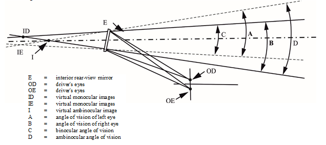
| 12.2. | "Ambinocular vision" means the total field of vision obtained by the superimposition of the monocular fields of the right eye and the left eye (see Figure 3 below). | a0c0 |
| ... | Figure 3 | a0c0 |
| ... |
|
a0c0 |
| 12.3. | "Type of vehicle as regards indirect vision" means motor vehicles which are identical in respect of the following basic features: | a0c0 |
| 12.3.1. | Type of device for indirect vision; | a0c0 |
| 12.3.2. | The bodywork features which reduce the field of vision; | a0c0 |
| 12.3.3. | The coordinates of point R (where applicable); | a0c0 |
| 12.3.4. | The prescribed positions, and type-approval markings of compulsory and (if fitted) optional devices for indirect vision. | a0c0 |
| 12.4. | "Vehicles of categories L2, L5, M1, M2, M3, N1, N2 and N3" means those defined in the Consolidated Resolution on the Construction of Vehicles (R.E.3), (document ECE/TRANS/WP.29/78/Rev.4, para. 2). | a0c0 |
| 12.5. | "Forward control" means a configuration in which more than half of the engine length is rearward of the foremost point of the windshield base and the steering wheel hub in the forward quarter of the vehicle length. | a0c0 |
| 12.6. | "Ocular reference point" means the middle point between the driver's ocular points. | a0c0 |
| 13. |
|
a0c0 |
| 13.1. | The application for approval of a vehicle type with regard to the installation of devices for indirect vision shall be submitted by the vehicle manufacturer or by his duly accredited representative. | a0c0 |
| 13.2. | A model of information document is shown in Annex 2. | a0c0 |
| 13.3. | A vehicle representative of the vehicle type to be approved shall be submitted to the Technical Service responsible for conducting the approval tests. | a0c0 |
| 13.4. | The Type Approval Authority shall verify the existence of satisfactory arrangements for ensuring effective checks on conformity of production before type-approval is granted. | a0c0 |
| 13.5. | The CMS shall be provided by the applicant with the following documents: | a0c0 |
| ... | a) Technical specification of the CMS; | a0c0 |
| ... | b) Operator's manual; | a0c0 |
| ... | c) Documentation referred to in Annex 12, paragraph 2.3. | a0c0 |
| ... | d) Documentation referred to in paragraph 16.1.1.1.1., if applicable. | a5c0 |
| 14. |
|
a0c0 |
| 14.1. | If the vehicle type submitted for approval in accordance with paragraph 13. above meets the requirements of paragraph 15. of this Regulation, approval shall be granted. | a0c0 |
| 14.2. | An approval number shall be assigned to each type approved. Its first two digits (at present 04) shall indicate the series of amendments incorporating the most recent or technical amendments made to the Regulation at the time of issue of the approval. The same Contracting Party shall not assign the same number to another vehicle type. | a0c0 |
| 14.3. | Notice of approval or of refusal or of extension or withdrawal of approval of a vehicle type pursuant to this Regulation shall be communicated to the Parties to the Agreement which apply this Regulation by means of a form conforming to the model in Annex 4 to this Regulation. | a0c0 |
| 15. |
|
a0c0 |
| 15.1. | General | a0c0 |
| 15.1.1. | The compulsory and optional devices for indirect vision, set out in the table under paragraph 15.2.1.1.1. below, installed on the vehicle shall be of a type approved under this Regulation. | a0c0 |
| 15.1.2. | Devices for indirect vision shall be fitted in such a way that the devices do not move so as significantly to change the field of vision as measured or vibrate to an extent which would cause the driver to misinterpret the nature of the image perceived. | a0c0 |
| 15.1.3. | The conditions laid down in paragraph 15.1.2. above shall be maintained when the vehicle is moving at speeds of up to 80 per cent of its maximum design speed, but not exceeding 150 km/h. | a0c0 |
| 15.1.4. | The fields of vision defined below shall be established using ambinocular vision, the eyes being at the "driver's ocular points" as defined in paragraph 12.1. above. The fields of vision shall be determined when the vehicle is in running order as defined in the consolidated Resolution on the Construction of vehicles (R.E.3) (ECE/TRANS/WP.29/78/Rev.4, para. 2.2.5.4.), plus for M1 and N1 vehicles one front seat passenger (75 kg). When established through windows, the glazing shall have a total light transmission factor in accordance with Regulation No. 43, Annex 21. | a0c0 |
| 15.2. | Devices for indirect vision | a0c0 |
| 15.2.1. | Number | a0c0 |
| 15.2.1.1. | Minimum number of compulsory devices for indirect vision | a0c0 |
| 15.2.1.1.1. | The fields of vision prescribed in paragraph 15.2.4. below shall be obtained from the minimum number of mandatory mirrors or camera-monitor devices set out in the following table. | a0c0 |
| ... | A minimum number of camera-monitor systems is undefined, but they shall provide the same field of vision as given in the table below and the provision on the minimum mounting height does not apply. | a0c0 |
| ... | In the case of camera-monitor systems, the maximum number of monitors shall not exceed the corresponding number of mirrors. | a0c0 |
| 15.2.1.1.2. | In the case a camera-monitor system is used for rendering (the) field(s) of vision, the relevant field(s) of vision shall be permanently visible to the driver when the ignition is on or the vehicle master control switch is activated (whichever is applicable) and not used for other information. However, when the vehicle is moving forward at a speed above 10 km/h or backwards, the monitor or the part of the monitor intended for rendering the Class VI field of vision may be used for other information. Multiple images may be used or displayed provided that the monitor has been approved in this mode. | a5c0 |
| 15.2.1.1.3. | Rear-view mirrors required for L-category vehicles with body work | a0c0 |
| ... |
|
a0c0 |
|
|
|
a0c0 |
| ... | Where a single Class III or VII rear-view mirror is fitted this shall be located on the left hand side of the vehicle in those countries where the traffic drives on the right and on the right hand side of the vehicle in those countries where the traffic drives on the left. | a0c0 |
| ... |

|
a0c0 |
| ... |

|
a0c0 |
| ... |
|
a0c0 |
| ... |
|
a0c0 |
| 15.2.1.1.4. | Optional rear-view mirrors for L-category vehicles | a0c0 |
| ... | The fitting of a Class III or VII rear-view mirror on the side of the vehicle opposite to that of the mandatory rear-view mirror referred to in paragraph 15.2.1.1.3. above, is permissible. The rear-view mirror shall meet the requirements of this Regulation. | a0c0 |
| 15.2.1.2. |
The provisions of this Regulation do not apply to the surveillance mirrors defined in paragraph 2.1.1.3. Nevertheless, the exterior surveillance mirrors shall be mounted at least 2 m above the ground when the vehicle is under a load corresponding to its maximum technical permissible mass |
a1c0 |
| 15.2.2. | Position | a0c0 |
| 15.2.2.1. | Devices for indirect vision shall be so placed that the driver, when sitting on the driving seat in a normal driving position, has a clear view of the road to the rear, side(s) or front of the vehicle. | a0c0 |
| 15.2.2.2. | Classes II to VII mirrors shall be visible through the side windows or through the portion of the windscreen that is swept by the windscreen wiper. Nevertheless, for design reasons, this last provision (i.e. the provisions relating the cleaned part of the windscreen) shall not apply to: | a0c0 |
| ... | a) Classes II to VII mirrors on the passenger side and optional exterior mirrors on the driver side of vehicles of categories M2 and M3; | a0c0 |
| ... | b) Class VI front-view mirrors. | a0c0 |
| 15.2.2.3. | In the case of any vehicle, which is in chassis/cab form when the field of vision is measured, the minimum and maximum body widths shall be stated by the manufacturer and, if necessary, simulated by dummy headboards. All vehicles and devices for indirect vision configurations taken into consideration during the tests shall be shown on the type-approval certificate for a vehicle with regard to the installation of devices for indirect vision (see Annex 4). | a0c0 |
| 15.2.2.4. | The prescribed Classes II, III, IV and VII mirror or monitor on the driver's side of the vehicle shall be so located that an angle of not more than 55° is formed between the vertical longitudinal median plane of the vehicle and the vertical plane passing through the centre of the mirror or monitor and through the centre of the straight line 65 mm long which joins the driver's two ocular points. | a0c0 |
| 15.2.2.5. | Devices for indirect vision shall not project beyond the external bodywork of the vehicle substantially more than is necessary to comply with the requirements concerning fields of vision laid down in paragraph 15.2.4. below. | a0c0 |
| 15.2.2.6. | Where the lower edge of a Classes II to VII mirror is less than 2 m above the ground when the vehicle is loaded to its technically permissible maximum laden mass, this mirror shall not project more than 250 mm beyond the overall width of the vehicle measured without mirrors. | a0c0 |
| 15.2.2.7. | Class V and Class VI mirrors shall be mounted on vehicles in such a way that, regardless of their position after adjustment, no part of these mirrors or their holders is less than 2 m from the ground when the vehicle is under a load corresponding to its technically permissible maximum laden mass. | a0c0 |
| ... | These mirrors shall not, however, be mounted on vehicles the cab height of which is such as to prevent compliance with this requirement. In this case another device for indirect vision is not mandatory. | a0c0 |
| 15.2.2.8. | Subject to the requirements of paragraphs 15.2.2.5., 15.2.2.6. and 15.2.2.7. above, devices for indirect vision may project beyond the permissible maximum widths of vehicles. | a0c0 |
| 15.2.2.9. | All Class VII mirrors shall be attached in such a way that they remain in a stable position under normal vehicle driving conditions. | a0c0 |
| 15.2.3. | Adjustment | a0c0 |
| 15.2.3.1. | If a Class I mirror is fitted, it shall be capable of being adjusted by the driver from the driving position. | a0c0 |
| 15.2.3.2. | If a Class II, III, IV or VII mirror is fitted on the driver's side, it shall be capable of being adjusted from inside the vehicle while the door is closed, although the window may be open. The mirror may, however, be locked in position from the outside. | a0c0 |
| 15.2.3.3. | The requirements of paragraph 15.2.3.2. above do not apply to mirrors which, after having been knocked out of alignment, can be returned to their former position without the need for adjustment. | a0c0 |
| 15.2.4. | Fields of vision | a0c0 |
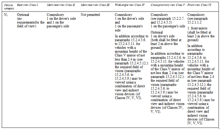
| 15.2.4.1. | Class I rear-view device | a0c0 |
| ... | The field of vision shall be such that the driver can see at least a 20 m wide, flat, horizontal portion of the road centred on the vertical longitudinal median plane of the vehicle and extending from 60 m behind the driver's ocular points (Figure 4) to the horizon. | a0c0 |
| ... | Figure 4 | a0c0 |
| ... | Class I field of vision | a0c0 |
| ... |
|
a0c0 |
| 15.2.4.2. | Class II main rear-view device | a0c0 |
| 15.2.4.2.1. | Main rear-view device on the driver's side | a0c0 |
| ... | The field of vision shall be such that the driver can see at least a 5 m wide, flat, horizontal portion of the road, which is bounded by a plane which is parallel to the median longitudinal vertical plane and passing through the outermost point of the vehicle on the driver's side of the vehicle and extends from 30 m behind the driver's ocular points to the horizon. | a0c0 |
| ... | In addition, the road shall be visible to the driver over a width of 1 m, which is bounded by a plane parallel to the median longitudinal vertical plane and passing through the outermost point of the vehicle starting from a point 4 m behind the vertical plane passing through the driver's ocular points (see Figure 5). | a0c0 |
| 15.2.4.2.2. | Main rear-view device on the passenger's side | a0c0 |
| ... | The field of vision shall be such that the driver can see at least a 5 m wide, flat, horizontal portion of the road, which is bounded on the passenger's side by a plane parallel to the median longitudinal vertical plane of the vehicle and passing through the outermost point of the vehicle on the passenger's side and which extends from 30 m behind the driver's ocular points to the horizon. | a0c0 |
| ... | In addition, the road shall be visible to the driver over a width of 1 m, which is bounded by a plane parallel to the median longitudinal vertical plane and passing through the outermost point of the vehicle starting from a point 4 m behind the vertical plane passing through the driver's ocular points (see Figure 5). | a0c0 |
| ... | Figure 5 | a0c0 |
| ... | Class II fields of vision | a0c0 |
| ... |

|
a0c0 |
| 15.2.4.3. | Class III main rear-view device | a0c0 |
| 15.2.4.3.1. | Main rear-view device on the driver's side | a0c0 |
| ... | The field of vision shall be such that the driver can see at least a 4 m wide, flat, horizontal portion of the road, which is bounded by a plane parallel to the median longitudinal vertical plane and passing through the outermost point of the vehicle on the driver's side of the vehicle and extends from 20 m behind the driver's ocular points to the horizon (see Figure 6). | a0c0 |
| ... | In addition, the road shall be visible to the driver over a width of 1 m, which is bounded by a plane parallel to the median longitudinal vertical plane and passing through the outermost point of the vehicle starting from a point 4 m behind the vertical plane passing through the driver's ocular points. | a0c0 |
| 15.2.4.3.2. | Main rear-view device on the passenger's side | a0c0 |
| ... | The field of vision shall be such that the driver can see at least a 4 m wide flat, horizontal portion of the road which is bounded by a plane parallel to the median longitudinal vertical plane passing through the outermost point of the vehicle on the passenger's side and which extends from 20 m behind the driver's ocular points to the horizon (see Figure 6). | a0c0 |
| ... | In addition, the road shall be visible to the driver over a width of 1 m, which is bounded by a plane parallel to the median longitudinal vertical plane and passing through the outermost point of the vehicle starting from a point 4 m behind the vertical plane passing through the driver's ocular points. | a0c0 |
| ... | Figure 6 | a0c0 |
| ... | Class III fields of vision | a0c0 |
| ... |
|
a0c0 |
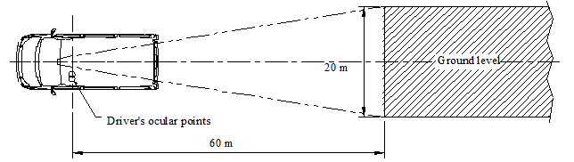
| 15.2.4.4. | Class IV wide-angle view device | a0c0 |
| 15.2.4.4.1. | Wide-angle view device on the driver's side | a0c0 |
| ... | The field of vision shall be such that the driver can see at least a 15 m wide, flat, horizontal portion of the road, which is bounded by a plane parallel to the median longitudinal vertical plane of the vehicle and passing through the outermost point of the vehicle on the driver's side and which extends from at least 10 m to 25 m behind the driver's ocular points. | a0c0 |
| ... | In addition, the road shall be visible to the driver over a width of 4.5 m, which is bounded by a plane parallel to the median longitudinal vertical plane and passing through the outermost point of the vehicle starting from a point 1.5 m behind the vertical plane passing through the driver's ocular points (see Figure 7). | a0c0 |
| 15.2.4.4.2. | Wide-angle view device on the passenger's side | a0c0 |
| ... | The field of vision shall be such that the driver can see at least a 15 m wide, flat, horizontal portion of the road, which is bounded by a plane parallel to the median longitudinal vertical plane of the vehicle and passing through the outermost point of the vehicle on the passenger's side and which extends from at least 10 m to 25 m behind the driver's ocular points. | a0c0 |
| ... | In addition, the road shall be visible to the driver over a width of 4.5 m, which is bounded by a plane parallel to the median longitudinal vertical plane and passing through the outermost point of the vehicle starting from a point 1.5 m behind the vertical plane passing through the driver's ocular points (see Figure 7). | a0c0 |
| ... | Figure 7 | a0c0 |
| ... | Class IV fields of vision | a0c0 |
| ... |
|
a0c0 |
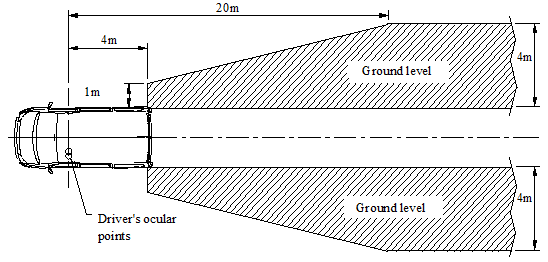
| 15.2.4.5. | Class V close-proximity view device | a0c0 |
| ... | The field of vision shall be such that the driver can see a flat horizontal portion of the road along the side of the vehicle, bounded by the following vertical planes (see Figures 8a and 8b): | a0c0 |
| 15.2.4.5.1. | The plane parallel to the median longitudinal vertical plane of the vehicle which passes through the outermost point of the vehicle cab on the passenger's side; | a0c0 |
| 15.2.4.5.2. | In the transverse direction, the parallel plane passing at a distance of 2 m in front of the plane mentioned in paragraph 15.2.4.5.1. above. | a0c0 |
| 15.2.4.5.3. | To the rear, the plane parallel to the vertical plane passing through the driver's ocular points and situated at a distance of 1.75 m behind that plane; | a0c0 |
| 15.2.4.5.4. | To the front, the plane parallel to the vertical plane passing through the driver's ocular points and situated at a distance of 1 m in front of that plane. If the vertical transverse plane passing through the leading edge of the vehicle bumper is less than 1 m in front of the vertical plane passing through the driver's ocular points, the field of vision shall be limited to that plane. | a0c0 |
| 15.2.4.5.5. | In the case the field of vision described in Figures 8a and 8b can be perceived through the combination of the field of vision from a Class IV wide-angle view device and that of a Class VI front-view device, the installation of a Class V close-proximity view device is not compulsory. | a0c0 |
| ... | Figures 8a and 8b | a0c0 |
| ... | Class V field of vision | a0c0 |
| ... | Figure 8a | a0c0 |
| ... |
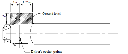
|
a0c0 |
| ... | Figure 8b | a0c0 |
| ... |
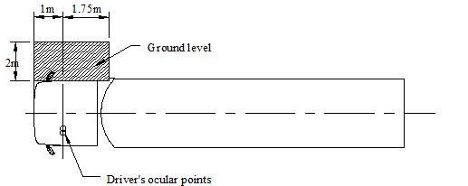
|
a0c0 |
| 15.2.4.5.6. | On the passenger side only, the field of vision shall also be such that the driver can see a flat horizontal portion of the road along the side of the vehicle which is outside the field defined in paragraphs 15.2.4.5.1. to 15.2.4.5.4. above but within the field bounded by the following vertical planes; the front of this field of vision may be rounded off with a radius of 2,000 mm (see Figures 8c and 8d): | a0c0 |
| 15.2.4.5.7. | In the transverse direction, the parallel plane passing at a distance of 4.5 m in front of the plane mentioned in paragraph 15.2.4.5.1. above. | a0c0 |
| 15.2.4.5.8. | To the rear, the plane parallel to the vertical plane passing through the driver's ocular points and situated at a distance of 1.75 m behind that plane. | a0c0 |
| 15.2.4.5.9. | To the front, the plane parallel to the vertical plane passing through the driver's ocular points and situated at a distance of 3 m in front of that plane. This field of vision may be partially provided by a front-view device (Class VI). | a0c0 |
| 15.2.4.5.10. | The field of vision prescribed in paragraphs 15.2.4.5.6. to 15.2.4.5.9. above may be partially provided by a wide-angle view device (Class IV) or a combination of a close-proximity view device (Class V) and a front-view device (Class VI). | a0c0 |
| 15.2.4.5.11. | The area prescribed in paragraphs 15.2.4.5.6. to 15.2.4.5.9. above may be viewed using a combination of direct view and indirect vision devices (of Class IV, V, VI). | a0c0 |
| 15.2.4.5.11.1. | If an indirect vision device of Class IV is used to provide a part of the field of vision prescribed in paragraphs 15.2.4.5.6. to 15.2.4.5.9., it shall be adjusted in a way that it simultaneously provides the field of vision prescribed in paragraph 15.2.4.4.2. | a0c0 |
| 15.2.4.5.11.2. | If an indirect vision device of Class V is used to provide a part of the field of vision prescribed in paragraphs 15.2.4.5.6. to 15.2.4.5.9., it shall be adjusted in a way that it simultaneously provides the field of vision prescribed in paragraphs 15.2.4.5.1. to 15.2.4.5.4. | a0c0 |
| 15.2.4.5.11.3. | If an indirect vision device of Class VI is used to provide a part of the field of vision prescribed in paragraphs 15.2.4.5.6. to 15.2.4.5.9., it shall be adjusted in a way that it simultaneously provides the field of vision prescribed in paragraph 15.2.4.6.1. | a0c0 |
| 15.2.4.5.12. | The field of vision prescribed in paragraphs 15.2.4.5.1. to 15.2.4.5.4. may be viewed using a combination of a close-proximity view device (Class V) and a wide-angle view device (Class IV). | a0c0 |
| ... | In such cases the close-proximity view mirror (Class V) shall provide at least 90 per cent of the field of vision prescribed in paragraphs 15.2.4.5.1 to 15.2.4.5.4. and the Class IV mirror shall be adjusted in a way that it simultaneously provides the field of vision prescribed in paragraph 15.2.4.4.2. | a0c0 |
| 15.2.4.5.13. | Paragraphs 15.2.4.5.6. to 15.2.4.5.12. above shall not apply to a vehicle where any part of a Class V mirror, if fitted, or its holder, is less than 2.4 m above the ground, regardless of its position after adjustment. | a0c0 |
| 15.2.4.5.14. | Paragraphs 15.2.4.5.6. to 15.2.4.5.12. above shall not apply to a vehicle of category M2 or M3. | a0c0 |
| ... | Figures 8c and 8d | a0c0 |
| ... | Larger field of vision on the passenger side | a0c0 |
| ... | Figure 8c | a0c0 |
| ... |
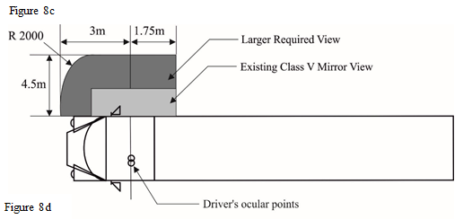
|
a0c0 |
| ... |

|
a0c0 |
| 15.2.4.6. | Class VI front-view device | a0c0 |
| 15.2.4.6.1. | The field of vision shall be such that the driver can see at least a flat horizontal portion of the road, which is bounded by: | a0c0 |
| ... | a) A transverse vertical plane through the outermost point of the front of the vehicle; | a0c0 |
| ... | b) A transverse vertical plane 2,000 mm in front of the plane defined in (a); | a0c0 |
| ... | c) A longitudinal vertical plane parallel to the longitudinal vertical median plane going through the outermost side of the vehicle at the driver's side; and | a0c0 |
| ... | d) A longitudinal vertical plane parallel to the longitudinal vertical median plane 2,000 mm outside the outermost side of the vehicle opposite to the driver's side. | a0c0 |
| ... | The front of this field of vision opposite to the driver's side may be rounded off with a radius of 2,000 mm (see Figure 9). | a0c0 |
| ... | For the defined field of vision, see also paragraph 15.2.4.9.2. below. | a0c0 |
| ... | The provisions for Class VI front-view devices are compulsory for forward controlled (as defined in paragraph 12.5. of this Regulation) vehicles of categories N2 > 7.5 t and N3. | a0c0 |
| ... | If vehicles of these categories cannot fulfil the requirements by using a front-view device, a vision support system shall be used. In the case of a vision support system this device shall be able to detect an object of 50 cm height and with a diameter of 30 cm within the field defined in Figure 9. | a0c0 |
| ... | Figure 9 | a0c0 |
| ... | Class VI field of vision | a0c0 |
| ... |

|
a0c0 |
| 15.2.4.6.2. | However, if the driver can see, taking into account the obstructions by the A-pillars, a straight line 300 mm in front of the vehicle at a height of 1,200 mm above the road surface and which is situated between a longitudinal vertical plane parallel to the longitudinal vertical median plane going through the outermost side of the vehicle at the driver's side and a longitudinal vertical plane parallel to the longitudinal vertical median plane 900 mm outside the outermost side of the vehicle opposite to the driver's side, a Class VI device for indirect vision is not mandatory. | a0c0 |
| 15.2.4.6.3. | For the purpose of paragraphs 15.2.4.6.1. and 15.2.4.6.2. above parts permanently attached to the vehicle that are situated both above the driver's eye points and in front of the transverse vertical plane passing through the foremost surface of the vehicle's front bumper shall not be taken into account when defining the front of the vehicle. | a0c0 |
| 15.2.4.7. | Class VII main rear-view mirror | a0c0 |
| 15.2.4.7.1. | Main rear-view mirror on the driver's side | a0c0 |
| ... | The field of vision shall be such that the driver can see at least a 2.50 m wide, flat, horizontal portion of the road, which is bounded by a plane parallel to the median longitudinal vertical plane and passing through the outermost point of the vehicle on the driver's side of the vehicle and extends from 10 m behind the driver's ocular points to the horizon (see Figure 10). | a0c0 |
| 15.2.4.7.2. | Main rear-view mirror on the passenger's side | a0c0 |
| ... | The field of vision shall be such that the driver can see at least a 4 m wide flat, horizontal portion of the road which is bounded by a plane parallel to the median longitudinal vertical plane passing through the outermost point of the vehicle on the passenger's side and which extends from 20 m behind the driver's ocular points to the horizon (see Figure 10). | a0c0 |
| ... | Figure 10 | a0c0 |
| ... | Class VII fields of vision | a0c0 |
| ... |
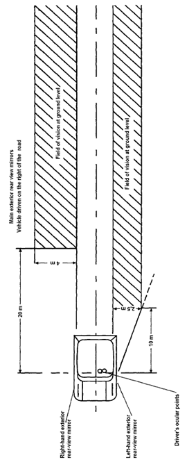
|
a0c0 |
| 15.2.4.8. | In the case of mirrors consisting of several reflecting surfaces which are either of different curvature or make an angle with each other, at least one of the reflecting surfaces shall provide the field of vision and have the dimensions (paragraph 6.1.2.1.2.2. of this Regulation) specified for the class to which they belong. | a0c0 |
| 15.2.4.9. | Obstructions | a0c0 |
| 15.2.4.9.1. | Class I rear-view devices | a0c0 |
| ... | The field of vision may be reduced by the presence of devices such as sun visors, windscreen wipers, heating elements and stop lamp of category S3, provided that all these devices together do not obscure more than 15 per cent of the prescribed field of vision. Headrests or framework or bodywork such as window columns of rear split doors, rear window frame shall be excluded from the calculation. This requirement shall be tested by projection on to a vertical plane at right angles to the longitudinal centre plane of the vehicle. The degree of obstruction shall be measured with the sun visors folded back. | a0c0 |
| 15.2.4.9.2. | Classes II, III, IV, V, and VI devices for indirect vision and Class VII mirrors | a0c0 |
| ... | In the fields of vision specified above, obstruction due to the bodywork and its components, such as other cab devices for indirect vision, door handles, outline marker lights, direction indicators and front and rear bumpers, as well as reflective-surface cleaning components, shall not be taken into account if they are responsible for a total obstruction of less than 10 per cent of the specified field of vision. In the case of a vehicle designed and constructed for special purposes where, due to its special features, it is not possible to meet this requirement, the obstruction of the required field of vision of a Class VI mirror caused by the special features may be more than 10 per cent but not more than necessary for its special function. | a0c0 |
| 15.2.4.10. | Test procedure | a0c0 |
| ... | The field of vision shall be determined by placing powerful light sources at the ocular points and examining the light reflected on the vertical monitoring screen. Other equivalent methods may be used. | a0c0 |
| 16. |
|
a0c0 |
| 16.1 | Class I to IV camera-monitor devices (see Annex 12) | a0c0 |
| ... | Unless otherwise provided in this Regulation, the definitions and symbols used in paragraph 16.1. are in accordance with ISO 16505:2015, Chapters 3 and 4. | a0c0 |
| ... | Unless otherwise provided in this Regulation, the requirements given in paragraph 16.1. shall be verified according to the test procedures given in ISO 16505:2015, Chapter 7, where available. | a0c0 |
| 16.1.1. | Intended use, activation and deactivation | a0c0 |
| ... | The intended use shall be mentioned within the operator's manual. The procedure for activation and deactivation of the CMS of Classes II and III shall allow a safe use of the vehicle. | a0c0 |
| ... | The CMS shall be activated when the vehicle is opened (e.g. unlocking of the doors, opening of a front door or any other means by the choice of the manufacturer). | a0c0 |
| ... | In addition to the requirements mentioned in paragraph 15.2.1.1.2., after each engine switch-off the system shall remain operational for a period of at least T1 = 120 s. After T1 period and for a period of at least T2 = (420-T1) seconds the system shall be able to be reactivated such that the required field of vision is made available within 1 second by manoeuvring any front door opening automatically and, if available, manually by the driver. After T2 period the system shall be able to be reactivated within 7 seconds (e.g. by initiating any front door opening process). | a0c0 |
| ... | Notwithstanding the provisions above, any other concept to activate or deactivate the system shall be demonstrated to the satisfaction of the Technical Service within the safety concept that is provided according to the provisions in Annex 12, paragraph 2. | a0c0 |
| 16.1.1.1. | Default view | a0c0 |
| ... | In default view the CMS shall show the field of view at least as defined in paragraph 15.2.4., with at least the required magnification and resolution as defined in paragraph 16.1.3. | a0c0 |
| ... | In the case of mirror and CMS dual function system of Class I, the CMS mode shall be set by the driver. Activation and deactivation device shall be located directly on the mirror and CMS dual function system. | a0c0 |
|
|
Temporarily modified view |
a5c0 |
| 16.1.1.2. | Luminance and contrast adjustment | a0c0 |
| ... | If manual adjustment is provided, the operator's manual shall provide information on how to change the luminance/contrast. | a0c0 |
| 16.1.1.3. | Overlay requirements within the minimum required field of vision | a0c0 |
| ... |
Overlays shall display only |
a4c0 |
| ... |
|
a4c0 |
| ... | All overlays shall be considered as an obstruction regardless of their transparency. | a0c0 |
| ... | Each overlay shall not exceed 2.5 per cent of the required field of view displayed surface of the corresponding class. | a0c0 |
| ... | The total surface of all obstructions shall not exceed the provision of paragraph 15.2.4.9.1. or 15.2.4.9.2. at the same time. | a0c0 |
| ... | Overlay and any other obstruction surface shall be determined (for example on screenshots) taking into account the worst case(s). | a0c0 |
| 16.1.2. | Operating readiness (System availability) | a0c0 |
| ... | Non-operation of the system shall be recognizable to the driver is (e.g. CMS failure by, i.e. warning indication, display information, absence of status indicator). The information for the driver shall be explained in the operator's manual. | a0c0 |
| 16.1.3. | Magnification and resolution | a0c0 |
| 16.1.3.1. | Magnification factor | a0c0 |
| ... |
The minimum and the average magnification factors of the CMS, in both horizontal and vertical directions shall not be lower than the |
a3c0 |
| ... | The minimum magnification factor shall not be less than: | a0c0 |
| ... | a) for Class I: 0.31; | a0c0 |
| ... | b) for Class II (driver's side): 0.26; | a0c0 |
| ... | c) for Class III (driver's side): 0.29; | a0c0 |
| ... | d) for Class IV (driver's side): 0.054; | a0c0 |
| ... | e) for Class II (passenger's side): 0.13; | a0c0 |
| ... | f) for Class III (passenger's side): 0.19; | a0c0 |
| ... | g) for Class IV (passenger's side): 0.016. | a0c0 |
| ... | The average magnification factor shall not be less than: | a0c0 |
| ... | h) for Class I: 0.33; | a0c0 |
| ... | i) for Class II (driver's side): 0.31; | a0c0 |
| ... | j) for Class III (driver's side): 0.31; | a0c0 |
| ... | k) for Class IV (driver's side): 0.091; | a0c0 |
| ... | l) for Class II (passenger's side): 0.16; | a0c0 |
| ... | m) for Class III (passenger's side): 0.20; | a0c0 |
| ... | n) for Class IV (passenger's side): 0.046. | a0c0 |
| 16.1.3.2. | Resolution (MTF) | a0c0 |
| ... | The resolution (MTF) defines the minimum distinguishable details observable in an image as is represented by the MTF10. For reasons of simplicity the requirement is defined assuming an aspect ratio of 1:1. | a0c0 |
| ... | Resolution MTF10, at the centre of the monitor defined size shall fulfil the following requirements: | a0c0 |
| ... |
|
a0c0 |
| ... |

|
a0c0 |
| 16.1.4 | Magnification aspect ratio | a0c0 |
| ... | In the required field of view, the difference between the average magnification factor for horizontal and vertical direction of a CMS shall satisfy the following equations depending on the individual mirror classes. | a0c0 |
| ... | For devices Class I the acceptable range shall be: | a0c0 |
| ... |

|
a0c0 |
| 16.1.5. | Monitor inside the vehicle | a0c0 |
| 16.1.5.1. | The centre of the monitor(s) shall not be below a plane passing through the driver's ocular points, as defined in paragraph 12.1., and declined 30° below. | a0c0 |
| 16.1.5.2. | The arrangement of the monitor(s) inside the vehicle shall be convenient to the driver. | a0c0 |
| ... | Thus, the image of the right side field of view shall be presented to the right of the longitudinal vertical plane through the ocular reference point, defined in paragraph 12.6. The image of the left side field of view shall be presented to the left of the longitudinal vertical plane through the ocular reference point. | a0c0 |
| ... | If the CMS shows more than one field of vision on the same display, non-continuous images shall be clearly separated from each other. If the field of vision from different classes of devices for indirect vision are shown on the monitor(s) without hiding any part of the required field of vision, a combined continuous image is allowed. In this case, a clear separation of the different fields of vision is not necessary and any changes in magnification may be indicated to the driver using indication lines. Indication lines shall not hide information. | a6c0 |
| 16.1.5.3. | The monitor defined size shall be visible without any obstruction from the ocular reference point. A virtual testing is acceptable. | a0c0 |
| 16.1.6. | Obstruction of the driver's direct view caused by the installation of a device for indirect vision shall be restricted to a minimum. | a0c0 |
| 16.1.7. | Decreasing accommodation | a0c0 |
| ... | The installation of the monitor inside the vehicle should follow the needs of the intended user group. The operator's manual shall provide information on the decreasing capacity of the human being to accommodate and shall recommend suitable assistance for the user's needs. | a0c0 |
| 16.1.8. | Safety of electronic systems for indirect vision | a0c0 |
| ... | The requirements to be applied to the safety aspects of electronic systems for indirect vision are given in Annex 12, paragraph 2. | a0c0 |
| 16.2. | Classes V and VI camera-monitor devices | a0c0 |
| 16.2.1. | A device for indirect vision shall give such performances that a critical object can be observed by the driver over the entire required field of vision, taking into account the critical perception according the procedure of Annex 10. | a0c0 |
| ... | Alternatively, the determination of the displayed object size shall be performed according to Annex 11. | a0c0 |
| 16.2.2. | Obstruction of the driver's direct view caused by the installation of a device for indirect vision shall be restricted to a minimum. | a0c0 |
| 16.2.3. | Installation requirements for the monitor | a0c0 |
| ... | The viewing direction of the monitor shall roughly be the same direction as the one for the main mirror. | a0c0 |
| 16.2.4. | Vehicles may be equipped with additional devices for indirect vision. | a0c0 |
| 16.2.5. | The provisions of this Regulation do not apply to the surveillance camera-monitor-recording devices defined in paragraph 2.3. of this Regulation. Exterior surveillance cameras either shall be mounted at least 2 m above the ground when the vehicle is under a load corresponding to its maximum technical permissible mass, or, if their lower edge is less than 2 m from the ground, shall not project more than 50 mm beyond the overall width of the vehicle measured without this device and have a radii of curvature of not less than 2.5 mm. | a0c0 |
| 17. |
|
a0c0 |
| 17.1. | Every modification of the vehicle type shall be notified to the Type Approval Authority which approved the vehicle type. Type Approval Authority shall then either: | a0c0 |
| ... | a) Decide, in consultation with the manufacturer, that a new type approval is to be granted; or | a0c0 |
| ... | b) Apply the procedure contained in paragraph 17.1.1. (Revision) and, if applicable, the procedure contained in paragraph 17.1.2. (Extension). | a0c0 |
| 17.1.1. | Revision | a0c0 |
| ... | When particulars recorded in the information folder have changed and the Type Approval Authority considers that the modifications made are unlikely to have an appreciable adverse effect, and that in any case the vehicle still complies with the requirements, the modification shall be designated a "revision". | a0c0 |
| ... | In such a case, the Type Approval Authority shall issue the revised pages of the information folder as necessary, marking each revised page to show clearly the nature of the modification and the date of re-issue. A consolidated, updated version of the information folder, accompanied by a detailed description of the modification, shall be deemed to meet this requirement. | a0c0 |
| 17.1.2. | Extension | a0c0 |
| ... | The modification shall be designated an "extension" if, in addition to the change of the particulars recorded in the information folder, | a0c0 |
| ... | a) Further inspections or tests are required; or | a0c0 |
| ... | b) Any information on the communication document (with the exception of its attachments) has changed; or | a0c0 |
| ... | c) Approval to a later series of amendments is requested after its entry into force. | a0c0 |
| 17.2. | Confirmation or refusal of approval, specifying the alterations, shall be communicated to the Parties to the Agreement which apply this Regulation by means of a form conforming to the model in Annex 4 to this Regulation. In addition, the index to the information package, attached to the communication document, shall be amended accordingly to show the date of the most recent revision or extension. | a0c0 |
| 17.3. | The Type Approval Authority issuing the extension of approval shall assign a series number to each communication form drawn up for such an extension. | a0c0 |
| 18. |
|
a0c0 |
| 18.1. | The conformity of production procedure shall comply with those set out in the Agreement, Appendix 2, (E/ECE/324-E/ECE/TRANS/505/Rev.2). | a0c0 |
| 18.2. | Every vehicle approved under this Regulation shall be so manufactured as to conform to the type approved by meeting the requirements set out in paragraph 15., and where applicable paragraph 16. above. | a0c0 |
| 19. |
|
a0c0 |
| 19.1. | The approval granted in respect of a vehicle type pursuant to this Regulation may be withdrawn if the requirement laid down in paragraph 18.1. above is not complied with or if the vehicle fails to pass the checks prescribed in paragraph 18.2. above. | a0c0 |
| 19.2. | If a Party to the Agreement which applies this Regulation withdraws an approval it has previously granted, it shall forthwith so notify the other Contracting Parties applying this Regulation by means of a copy of the approval form bearing at the end, in large letters, the signed and dated annotation "APPROVAL WITHDRAWN". | a0c0 |
| 20. |
|
a0c0 |
| ... | If the holder of the approval completely ceases to manufacture a type of vehicle approved in accordance with this Regulation, he shall so inform the Type Approval Authority which granted the approval. Upon receiving the relevant communication, the Authority shall inform thereof the other Parties to the Agreement applying this Regulation by means of a copy of the approval form bearing at the end, in large letters, the signed and dated annotation "PRODUCTION DISCONTINUED". | a0c0 |
| 21. |
|
a0c0 |
| ... | The Parties to the Agreement applying this Regulation shall communicate to the United Nations Secretariat the names and addresses of the Technical Services responsible for conducting approval tests and of the Type Approval Authorities which grant approval and to which forms certifying approval or refusal or extension or withdrawal of approval, issued in other countries, are to be sent. | a0c0 |
| 22. |
|
a0c0 |
| 22.1. | As from the official date of entry into force of the 03 series of amendments to this Regulation, no Contracting Party applying this Regulation shall refuse an application for approval under this Regulation as amended by the 03 series of amendments. | a0c0 |
| 22.2. | As from 12 months after entry into force of the 03 series of amendments to this Regulation, Contracting Parties applying this Regulation shall grant approvals to a type of device for indirect vision only if the type meets the requirements of this Regulation as amended by the 03 series of amendments. | a0c0 |
| 22.3. | As from 18 months after entry into force of the 03 series of amendments to this Regulation, Contracting Parties applying this Regulation shall grant approvals to a type of vehicle with regard to the installation of devices for indirect vision only if the type of vehicle meets the requirements of this Regulation as amended by the 03 series of amendments. | a0c0 |
| 22.4. | As from 24 months after entry into force of the 03 series of amendments to this Regulation, Contracting Parties applying this Regulation may refuse to recognize approvals of a type of vehicle with regard to the installation of a camera-monitor system for indirect vision or type of camera-monitor system for indirect vision which have not been granted in accordance with the 03 series of amendments to this Regulation. | a0c0 |
| 22.5. | As from 26 January 2010 for vehicles of category M1 and N1 and from 26 January 2007 for vehicles of other categories, Contracting Parties applying this Regulation may refuse to recognize approvals of a device for indirect vision which have not been granted in accordance with the 02 series of amendments to this Regulation. | a0c0 |
| 22.6. | Approvals which were granted to devices for indirect vision of Class I or III pursuant to this Regulation in its original form (00 series) or modified by the 01 or 02 series of amendments before the date of entry into force of the 03 series of amendments shall remain valid and Contracting Parties shall continue to accept them. Contracting Parties shall not refuse to grant extensions to approvals granted to the original version, the 01 or 02 series of amendments. | a0c0 |
| 22.7. | Notwithstanding the provisions of paragraph 22.2., approvals which were granted to mirrors of Classes II, IV, V, VI or VII pursuant to this Regulation as modified by the 02 series of amendments before the date of entry into force of the 03 series of amendments shall remain valid and Contracting Parties shall continue to accept them. Contracting Parties shall not refuse to grant extensions to approvals granted to the 02 series of amendments. | a0c0 |
| 22.8. | The provisions of this Regulation shall not prohibit the approval of a type of vehicle with regard to the mounting of devices for indirect vision pursuant to this Regulation as modified by the 03 series of amendments, if all or part of the devices for indirect vision of Class I or III, with which it is fitted, bear the approval mark prescribed by this Regulation in its original form (00 series) or modified by the 01 or 02 series of amendments. | a0c0 |
| 22.9. | The provisions of this Regulation shall not prohibit the approval of a type of vehicle with regard to the mounting of devices for indirect vision pursuant to this Regulation as modified by the 03 series of amendments, if all or part of the rear-view mirrors of Classes II, IV, V, VI or VII, with which it is fitted, bear the approval mark prescribed by the 02 series of amendments of this Regulation. | a0c0 |
| 22.10. | Notwithstanding the provisions of paragraphs 22.2., 22.4. and 22.5. above, for the purpose of replacement parts Contracting Parties applying this Regulation shall continue to grant approvals according 02 series of amendments to this Regulation, to devices for indirect vision for use on vehicle types which have been approved before the date mentioned in paragraph 22.2. above pursuant to the 02 series of amendments of Regulation No. 46, and, where applicable, subsequent extensions to these approvals. | a0c0 |
| 22.11. | As from the official date of entry into force of the 04 series of amendments to this Regulation, no Contracting Party applying this Regulation shall refuse an application for approval under this Regulation as amended by the 04 series of amendments. | a0c0 |
| 22.12. | As from 30 June 2014, Contracting Parties applying this Regulation shall grant approvals to a type of device for indirect vision only if the type of device meets the requirements of this Regulation as amended by the 04 series of amendments. | a0c0 |
| 22.13. | As from 30 June 2014, Contracting Parties applying this Regulation shall grant approvals to a type of vehicle with regard to the installation of devices for indirect vision only if the type of vehicle meets the requirements of this Regulation as amended by the 04 series of amendments. | a0c0 |
| 22.14. | As from 30 June 2015, Contracting Parties applying this Regulation shall not be obliged to accept approvals of a type of vehicle or type of device for indirect vision which have not been granted in accordance with the 04 series of amendments to this Regulation. | a0c0 |
| 22.15. | Notwithstanding paragraph 22.14. above, type approvals granted to the preceding series of amendments to the Regulation, which are not affected by the 04 series of amendments, shall remain valid and Contracting Parties applying this Regulation shall continue to accept them. | a0c0 |
| 22.16. | Contracting Parties applying this Regulation shall not refuse to grant extensions of type approvals for existing types of vehicles or devices, which are not affected by the 04 series of amendments, granted according to the 02 or 03 series of amendments to this Regulation. | a0c0 |
| 22.17. | Notwithstanding the provisions of paragraphs 22.2., 22.4., 22.5., 22.13. and 22.15. above, for the purpose of replacement parts, Contracting Parties applying this Regulation shall continue to grant approvals according to the 01 series of amendments to this Regulation, to devices for indirect vision of Classes I to V for use on vehicle types which have been approved before 26 January 2006 pursuant to the 01 series of amendments of Regulation No. 46 and, where applicable, subsequent extensions to these approvals. | a0c0 |
| A1 |
|
a0c0 |
| A1 |
|
a0c0 |
| A1 | The following information, if applicable, shall be supplied in triplicate and shall include a list of contents. | a0c0 |
| A1 | Any drawings shall be supplied in appropriate scale and in sufficient detail on size A4 paper or on a folder of A4 format. | a0c0 |
| A1 | Photographs, if any, shall show sufficient details. | a0c0 |
| A1 1. | Make (trade name of manufacturer): | a0c0 |
| A1 2. | Type and general commercial description(s): | a0c0 |
| A1 3. | Means of identification of the type, if indicated on the device: | a0c0 |
| A1 4. | Category of vehicle for which the device is intended: | a0c0 |
| A1 5. | Name and address of manufacturer: | a0c0 |
| A1 6. | Location and method of affixing of the approval mark: | a0c0 |
| A1 6.1. | Other mean of identification link to the approval mark: | a0c0 |
| A1 7. | Address(es) of assembly plant(s): | a0c0 |
| A1 8. | Mirrors (state for each mirror): | a0c0 |
| A1 8.1. | Variant | a0c0 |
| A1 8.2. | Drawing(s) for the identification of the mirror: | a0c0 |
| A1 8.3. | Details of the method of attachment: | a0c0 |
| A1 9. | Devices for indirect vision other than mirrors: | a0c0 |
| A1 9.1. | Type and characteristics (such as a complete description of the device): | a0c0 |
| A1 9.1.1. | In the case of camera-monitor systems of Classes V and VI, the class, the detection distance [mm], contrast, luminance range, glare correction, display performance (black and white/colour) image repetition frequency, luminance reach of the monitor: | a0c0 |
| A1 9.1.2. | In the case of camera-monitor systems of Classes I to IV, the class, field of view, magnification and resolution: | a0c0 |
| A1 9.2. | Sufficiently detailed drawings to identify the complete device including installation instructions; the position for the type-approval mark has to be indicated on the drawings: | a0c0 |
| A2 |
|
a0c0 |
| A2 |
|
a0c0 |
| A2 | The following information, if applicable, shall be supplied in triplicate and include a list of contents. | a0c0 |
| A2 | Any drawings shall be supplied in appropriate scale and in sufficient detail on size A4 paper or on a folder of A4 format. | a0c0 |
| A2 | Photographs, if any, shall show sufficient details. | a0c0 |
| A2 | General | a0c0 |
| A2 1. | Make (trade name of manufacturer): | a0c0 |
| A2 2. | Type and general commercial description(s): | a0c0 |
| A2 3. | Means of identification of type, if marked on the vehicle: | a0c0 |
| A2 4. | Location of that marking: | a0c0 |
| A2 5. | Category of vehicle: | a0c0 |
| A2 6. | Name and address of manufacturer: | a0c0 |
| A2 7. | Address(es) of assembly plant(s): | a0c0 |
| A2 | General construction characteristics of the vehicle | a0c0 |
| A2 8. | Photograph(s) and/or drawing(s) of a representative vehicle: | a0c0 |
| A2 9. | Driving cab (forward control or bonneted)[1]: | a0c0 |
| A2 10. | Driving position: left/right[1] | a0c0 |
| A2 10.1. | The vehicle is equipped to be driven in right-hand/left hand traffic[1] | a0c0 |
| A2 11. | Range of vehicle dimensions (overall): | a0c0 |
| A2 11.1 | For chassis without bodywork | a0c0 |
| A2 11.1.1. | Width[2]: | a0c0 |
|
A2 |
|
a0c0 |
|
A2 |
(a) Customs sealing devices and their protection; (b) Devices for securing the tarpaulin and their protection; (c) Tyre failure tell-tale devices; (d) Protruding flexible parts of a spray-suppression system; (e) Lighting equipment; (f) For buses, access ramps in running order, lifting platforms and similar equipment in running order provided that they do not exceed 10 mm from the side of the vehicle and the corners of the ramps facing forwards or rearwards are rounded to a radius of not less than 5 mm; the edges shall be rounded to a radius of not less than 2.5 mm; (g) Devices for indirect vision; (h) Tyre-pressure indicators; (i) Retractable steps; (j) The deflected part of the tyre walls immediately above the point of contact with the ground. |
a0c0 |
| A2 11.1.1.1. | Maximum permissible width: | a0c0 |
| A2 11.1.1.2. | Minimum permissible width: | a0c0 |
| A2 11.2. | For chassis with bodywork: | a0c0 |
| A2 11.2.1. | Width[2] | a0c0 |
| A2 12. | Bodywork | a0c0 |
| A2 12.1. | Devices for indirect vision | a0c0 |
| A2 12.1.1. | Mirrors | a0c0 |
| A2 12.1.1.1. | Drawing(s) showing the position of the mirror relative to the vehicle structure: | a0c0 |
| A2 12.1.1.2. | Details of the method of attachment including that part of the vehicle structure to which it is attached: | a0c0 |
| A2 12.1.1.3. | Optional equipment which may affect the rearward field of vision: | a0c0 |
| A2 12.1.1.4. | A brief description of the electronic components (if any) of the adjustment device: | a0c0 |
| A2 12.1.2. | Devices for indirect vision other than mirrors: | a0c0 |
| A2 12.1.2.1. | Sufficiently detailed drawings with the installation instructions: | a0c0 |
| A2 12.1.2.2. | In the case of camera-monitor system of Classes I to IV: | a0c0 |
| A2 12.1.2.2.1. | Drawing(s)/photograph(s) showing the position of the camera(s) relative to the vehicle structure: | a0c0 |
| A2 12.1.2.2.2. | Drawing(s)/photograph(s) showing the arrangement of the monitor(s) including surrounding interior parts: | a0c0 |
| A2 12.1.2.2.3. | Drawing(s)/photograph(s) showing the drivers view onto the monitor(s): | a0c0 |
| A2 12.1.2.2.4. | Drawing(s)/photograph(s) showing the setup and monitor image of the required field of view: | a0c0 |
| A2 12.1.2.2.5. | Details of the method of attachment of the camera-monitor device(s) including that part of the vehicle structure to which it is attached: | a0c0 |
| A2 12.1.2.2.6. | Optional equipment which may affect the rearward field of vision: | a0c0 |
| A2 12.1.2.2.7. | A brief description of the electronic components (if any) of the adjustment device: | a0c0 |
| A2 12.1.2.2.8. | A technical specification and operator's manual of the camera-monitor system according to ISO 16505:2015: | a0c0 |
|
A2 |
Documentation referred to in paragraph 16.1.1.1.1., if applicable: ............................................... | a0c0 |
| A3 |
|
a0c0 |
| A3 |
|
a0c0 |
| A3 | (Maximum format: A4 (210 x 297 mm)) | a0c0 |
| A3 |

|
a0c0 |
| A3 |
of a type of device for indirect vision pursuant to Regulation No. 46 |
a0c0 |
| A3 | Approval number: Extension No.: | a0c0 |
| A3 1. | Trade name or mark of device: | a0c0 |
| A3 2. | Manufacturer's name for the type of device: | a0c0 |
| A3 3. | Manufacturer's name and address: | a0c0 |
| A3 4. | If applicable, name and address of manufacturer's representative: | a0c0 |
| A3 5. | Submitted for approval on: | a0c0 |
| A3 6. | Technical Service responsible for conducting approval tests: | a0c0 |
| A3 7. | Date of report issued by that Service | a0c0 |
| A3 8. | Number of report issued by that Service | a0c0 |
| A3 9. | Brief description | a0c0 |
| A3 |
Identification of the device: mirror, camera/monitor, other devices for indirect vision of Classes I, II, III, IV, V, VI, |
a4c0 |
| A3 | Symbol as defined in paragraph 6.3.1.1. of this Regulation: yes/no[2] | a0c0 |
| A3 10. | Position of the approval mark: | a0c0 |
| A3 11. | Reason(s) for extension (if applicable): | a0c0 |
| A3 12. | Approval granted/refused/extended/withdrawn:[2] | a0c0 |
| A3 13. | Place: | a0c0 |
| A3 14. | Date: | a0c0 |
| A3 15. | Signature: | a0c0 |
| A3 16. | The list of documents deposited with the Type Approval Authority which has granted approval is annexed to this communication and may be obtained on request. | a0c0 |
|
A3 |
|
a0c0 |
|
A3 |
|
a0c0 |
| A4 |
|
a0c0 |
| A4 |
|
a0c0 |
| A4 | (Maximum format: A4 (210 x 297 mm)) | a0c0 |
| A4 |
|
a0c0 |
| A4 | of a type of vehicle with regard to the mounting of devices for indirect vision pursuant to Regulation No. 46 | a0c0 |
| A4 | Approval number: Extension No.: | a0c0 |
| A4 1. | Make (trade name of manufacturer): | a0c0 |
| A4 2. | Type and general commercial description(s) | a0c0 |
| A4 3. | Means of identification of type, if marked on the vehicle: | a0c0 |
| A4 3.1. | Location of that marking: | a0c0 |
| A4 4. |
Category of vehicle: (M1, M2, M3, N1, N2 ≤ 7.5 t, N2 > 7.5 t, N3, |
a3c0 |
| A4 5. | Name and address of manufacturer: | a0c0 |
| A4 6. | Address(es) of the production plant(s) | a0c0 |
| A4 7. | Additional information: (where applicable). See appendix | a0c0 |
| A4 8. | Technical Service responsible for carrying out the tests: | a0c0 |
| A4 9. | Date of test report: | a0c0 |
| A4 10. | Number of test report: | a0c0 |
| A4 11. | Remarks: (if any). See appendix | a0c0 |
| A4 12. | Place: | a0c0 |
| A4 13. | Date: | a0c0 |
| A4 14. | Signature: | a0c0 |
| A4 15. | The index to the information package lodged with the Type Approval Authority, which may be obtained on request is attached. | a0c0 |
|
A4 |
|
a0c0 |
|
A4 |
|
a0c0 |
| A4 | Annex 4 - Appendix | a0c0 |
| A4 | Appendix to type approval communication form No. ..... concerning the type approval of a vehicle with regard to the mounting of devices for indirect vision under Regulation No. 46 | a0c0 |
| A4 1. | Trade name or mark of mirrors and supplementary devices for indirect vision and component type-approval number: | a0c0 |
| A4 2. | Class(es) of mirrors and devices for indirect vision (I, II, III, IV, V, VI, VII, S)[1] | a0c0 |
| A4 3. | Extension of type approval of the vehicle to cover the following device for indirect vision | a0c0 |
| A4 4. | Data for identification of the R point of the driver's seating position: | a0c0 |
| A4 5. | Maximum and minimum bodywork width in respect of which the mirror and the devices for indirect vision has been granted type-approval (in the case of chassis/cab referred to in paragraph 15.2.2.3. of this Regulation) | a0c0 |
| A4 6. | The following documents, bearing the type approval number shown above, are annexed to this certificate: | a0c0 |
| A4 | a) Drawings showing the mounting of the devices for indirect vision | a0c0 |
| A4 | b) Drawings and plans showing the mounting position and characteristics of the part of the structure where the devices for indirect vision are mounted. | a0c0 |
| A4 7. | Remarks: (e.g. valid for right hand/left hand traffic[1]) | a0c0 |
|
A4 |
|
a0c0 |
| A5 |
|
a0c0 |
| A5 |
|
a0c0 |
| A5 | (See paragraph 5.4. of the Regulation) | a0c0 |
| A5 |

|
a0c0 |
| A5 | The above approval mark affixed to a device for indirect vision indicates that the device is a main rear-view device, of Class II, which has been approved in the Netherlands (E 4) pursuant to Regulation No. 46 and under approval number 042439. The first two digits of the approval number indicate that Regulation No. 46 already included the 04 series of amendments when the approval was granted. | a0c0 |
| A5 | Note: The approval number and the additional symbol shall be placed close to the circle and either above or below the "E" or to the left or right of that letter. The digits of the approval number shall be on the same side of the "E" and point in the same direction. The additional symbol shall be directly opposite the approval number. The use of Roman numerals as approval numbers shall be avoided so as to prevent any confusion with other symbols. | a0c0 |
| A6 |
|
a0c0 |
| A6 |
|
a0c0 |
| A6 1. | Definitions | a0c0 |
| A6 1.1. | CIE standard illuminate A[1]: Colorimetric illuminate, respecting the full radiator at T68 = 2,855.6 K. | a0c0 |
| A6 1.1.2. | CIE standard source A[1]: Gas-filled tungsten filament lamp operating at a correlated colour temperature of T68 = 2,855.6 K. | a0c0 |
| A6 1.1.3. |
|
a0c0 |
| A6 1.1.4. | CIE spectral tristimulus values[1]: Tristimulus values of the spectral components of an equi energy spectrum in the CIE (XYZ) system. | a0c0 |
| A6 1.1.5. | Photopic vision[1]: Vision by the normal eye when it is adapted to levels of luminance of at least several cd/m2. | a0c0 |
| A6 2. | Apparatus | a0c0 |
| A6 2.1. | General | a0c0 |
| A6 | The apparatus shall consist of a light source, a holder for the test sample, a receiver unit with a photodetector and an indicating meter (see Figure 1), and means of eliminating the effects of extraneous light. | a0c0 |
| A6 | The receiver may incorporate a light-integrating sphere to facilitate measuring the reflectance of non-flat (convex) mirrors (see Figure 2). | a0c0 |
| A6 2.2. | Spectral characteristics of light source and receiver | a0c0 |
| A6 | The light source shall consist of a CIE standard source A and associated optics to provide a near-collimated light beam. A voltage stabiliser is recommended in order to maintain a fixed lamp voltage during instrument operation. | a0c0 |
| A6 | The receiver shall have a photodetector with a spectral response proportional to the photopic luminosity function of the CIE (1931) standard colorimetric observer (see table). Any other combination of illuminate-filter-receptor giving the overall equivalent of CIE standard illuminate A and photopic vision may be used. When an integrating sphere is used in the receiver, the interior surface of the sphere shall be coated with a matt (diffusive) spectrally non-selective white coating. | a0c0 |
| A6 2.3. | Geometrical conditions | a0c0 |
| A6 | The angle of the incident beam ((θ) should preferably be 0.44 ± 0.09 rad (25 ± 5°) from the perpendicular to the test surface and shall not exceed the upper limit of the tolerance (i.e. 0.53 rad or 30°). The axis of the receptor | a0c0 |
|
A6 |
|
a0c0 |
| A6 | shall make an angle (θ) with this perpendicular equal to that of the incident beam (see Figure 1). The incident beam upon arrival at the test surface shall have a diameter of not less than 13 mm (0.5 inch). The reflected beam shall not be wider than the sensitive area of the photodetector, shall not cover less than 50 per cent of such area, and as nearly as possible shall cover the same area segment as used during instrument calibration. | a0c0 |
| A6 | When an integrating sphere is used in the receiver section, the sphere shall have a minimum diameter of 127 mm (5 inch). The sample and incident beam apertures in the sphere wall shall be of such a size as to admit the entire incident and reflected light beams. The photodetector shall be so located as not to receive direct light from either the incident or the reflected beam. | a0c0 |
| A6 2.4. | Electrical characteristics of the photodetector-indicator unit | a0c0 |
| A6 | The photodetector output as read on the indicating meter shall be a linear function of the light intensity of the photosensitive area. Means (electrical and/or optical) shall be provided to facilitate zeroing and calibration adjustments. Such means shall not affect the linearity or the spectral characteristics of the instrument. The accuracy of the receptor indicator unit shall be within ± 2 per cent of full scale, or ± 10 per cent of the magnitude of the reading, whichever is the smaller. | a0c0 |
| A6 2.5. | Sample holder | a0c0 |
| A6 | The mechanism shall be capable of locating the test sample so that the axes of the source arm and receptor intersect at the reflecting surface. The reflecting surface may lie within or at either face of the mirror sample, depending on whether it is a first surface, second surface or prismatic "flip" type mirror. | a0c0 |
| A6 3. | Procedure | a0c0 |
| A6 3.1. | Direct calibration method | a0c0 |
| A6 | In the direct calibration method, air is used as the reference standard. This method is applicable for those instruments, which are so constructed as to permit calibration at the 100 per cent point by swinging the receiver to a position directly on the axis of the light source (see Figure 1). | a0c0 |
| A6 | It may be desired in some cases (such as when measuring low-reflectivity surfaces) to use an intermediate calibration point (between 0 and 100 per cent on the scale) with this method. In these cases, a neutral density filter of known transmittance shall be inserted in the optical path, and the calibration control shall then be adjusted until the meter reads the percentage transmission of the neutral density filter. This filter shall be removed before reflectivity measurements are performed. | a0c0 |
| A6 3.2. | Indirect calibration method | a0c0 |
| A6 | The indirect calibration method is applicable in the case of instruments with fixed source and receiver geometry. A properly calibrated and maintained reflectance standard is required. This reference standard should preferably be a flat mirror with a reflectance value as near as possible to that of the test samples. | a0c0 |
| A6 3.3. | Flat mirror measurement | a0c0 |
| A6 | The reflectance of flat mirror samples can be measured on instruments employing either the direct or the indirect calibration method. The reflectance value is read directly from the indicating meter. | a0c0 |
| A6 3.4. | Non-flat (convex) mirror measurement | a0c0 |
| A6 | Measurement of the reflectance of non-flat (convex) mirrors requires the use of instruments which incorporate an integrating sphere in the receiver unit (see Figure 2). If the instrument-indicating meter indicates ne divisions with a standard mirror of E per cent reflectance, then, with a mirror of unknown reflectance, nx divisions will correspond to a reflectance of X per cent, in accordance with the formula: | a0c0 |
| A6 |

|
a0c0 |
| A6 | Figure 1 | a0c0 |
| A6 | Generalised reflectometer showing experimental set-ups for the two calibration methods | a0c0 |
| A6 |
|
a0c0 |
| A6 | Figure 2 | a0c0 |
| A6 | Generalised reflectometer, incorporating an integrating sphere in the receiver | a0c0 |
| A6 |
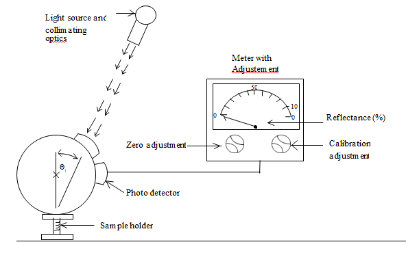
|
a0c0 |
| A6 4. | Spectral tristimulus values for the CIE 1931 standard colormetric observer[2] | a0c0 |
| A6 | This table is taken from CIE publication 50 (45) (1970) | a0c0 |
| A6 |

|
a0c0 |
|
A6 |

|
a0c0 |
| A6 | Explanatory figure | a0c0 |
| A6 | Example of device for measuring the reflection factor of spherical mirrors | a0c0 |
| A6 |

|
a0c0 |
| A7 |
|
a0c0 |
| A7 |
|
a0c0 |
| A7 1. | Measurement | a0c0 |
| A7 1.1. | Equipment | a0c0 |
| A7 | A "spherometer" similar to the one described in Figure 1 of this annex having the indicated distances between the tracing pin of the dial gauge and the fixed legs of the bar is used. | a0c0 |
| A7 1.2. | Measuring points | a0c0 |
| A7 1.2.1. | The principal radii of curvature shall be measured at three points situated as close as possible to positions at one-third, one-half and two-thirds of the distance along the arc of the reflecting surface passing through the centre of this surface and parallel to segment b, or of the arc passing through the centre of the reflecting surface which is perpendicular to it if this arc is the longer. | a0c0 |
| A7 1.2.2. | Where, owing to the size of the reflecting surface, it is impossible to obtain measurements in the directions defined in paragraph 2.1.1.5. of this Regulation, the Technical Services responsible for the tests may take measurements at the said point in two perpendicular directions as close as possible to those prescribed above. | a0c0 |
| A7 2. | Calculation of the radius of curvature "r" | a0c0 |
| A7 | "r" expressed in mm is calculated from the formula: | a0c0 |
| A7 |

|
a0c0 |
| A7 | Figure 1 | a0c0 |
| A7 | Spherometer | a0c0 |
| A7 |
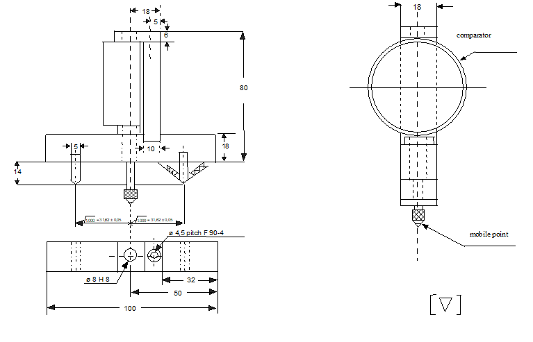
|
a0c0 |
| A8 |
|
a0c0 |
| A8 |
|
a0c0 |
|
A8 |
|
a0c0 |
| A8 |
|
a0c0 |
| A8 |
|
a0c0 |
| A8 |
|
a0c0 |
| A9 |
|
a0c0 |
| A9 |
|
a0c0 |
| A10 |
|
a0c0 |
| A10 |
|
a0c0 |
| A10 1. | Camera monitor device for indirect vision | a0c0 |
| A10 1.1. | Determination of the smallest discernable detail | a0c0 |
| A10 | The smallest discernable detail of the naked eye shall be defined according to standard ophthalmologic tests like the Landolt C test or the Triangle Orientation Discrimination (TOD) test. The smallest discernable detail at the centre of the viewing system can be determined using the Landolt C test or the TOD test. In the rest of the viewing area the smallest discernable detail may be estimated from the centrally determined smallest discernable detail and the local image deformation. For instance, in the case of a digital camera the smallest discernable detail at a given pixel location (in the monitor) scales inversely with the solid angle of the pixel. | a0c0 |
| A10 1.1.1. | Landolt-C test | a0c0 |
| A10 | In the Landolt-C test, test symbols are judged by the subject under test. In accordance with this test the smallest discernable detail is defined as the visual angle of the gap size of the Landolt C symbol at threshold size and is expressed in arcmin. The threshold size corresponds to the size at which the subject judges the orientation correctly in 75 per cent of the trials. The smallest discernable detail is determined in a test involving a human observer. A test chart containing test symbols is placed in front of the camera and the observer judges the orientation of test symbols from the monitor. From the threshold gap size of the Landolt C test symbol d [m] and the distance between the test pattern and the camera D [m] the smallest discernable detail ωc [arcmin] is calculated as follows: | a0c0 |
| A10 |

|
a0c0 |
| A10 1.1.2. | TOD test | a0c0 |
| A10 | The Landolt C test can be used to determine the smallest discernable detail of the camera-monitor system. However, for sensor systems it is more suitable to use the TOD (Triangle Orientation Discrimination) method which is similar to the Landolt C method, but involves equilateral triangular test patterns. The Triangle Orientation Discrimination method is described in detail by Bijl & Valeton (1999), who provide practical guidelines on how to perform a TOD measurement. In the method, triangular test patterns (see Figure 1) are viewed through the viewing system under test. Each triangle can have one out of four possible orientations (apex up, left, right or down) and the observer indicates/guesses for each triangle its orientation. When this procedure is repeated for many (randomly oriented) triangles of different sizes the fraction of correct responses can be plotted (see Figure 2), and increases with test pattern size. The threshold is defined as the point at which the fraction correct crosses the 0.75 level and can be obtained by fitting a smooth function through the data (see Bijl & Valeton, 1999). Critical perception is reached when the critical object diameter equals two times the width of the triangle at threshold size. The smallest discernable detail (ωc) is equal to 0.25 times the width of the triangle at threshold size. This means that, from the threshold triangle width w [m] and the distance between test pattern and the camera D [m] the smallest discernable detail ωc [arcmin] is calculated as follows: | a0c0 |
| A10 |

|
a0c0 |
| A10 | Figure 1 | a0c0 |
| A10 | Triangular test patterns used in the Triangle Orientation Discrimination (TOD) method | a0c0 |
| A10 |

|
a0c0 |
| A10 | Figure 2 | a0c0 |
| A10 | Typical relationship between the size of the triangle and the fraction of correct responses | a0c0 |
| A10 |
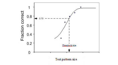
|
a0c0 |
| A10 1.2. | Determination of the critical viewing distance of the monitor | a0c0 |
| A10 | For a monitor having certain dimensions and properties, the distance to the monitor can be calculated within which the detection distance is dependent only on the performances of the camera. The critical viewing distance rmcrit is defined as the distance at which the smallest discernable detail displayed on the monitor spans 1 arcmin measured from the eye (the acuity threshold of a standard observer). | a0c0 |
| A10 |

|
a0c0 |
| A10 | Where: | a0c0 |
| A10 | rmcrit : critical viewing distance of the monitor [m] | a0c0 |
| A10 | δ : size of the smallest discernable detail on the monitor [m] | a0c0 |
| A10 1.3. | Determination of the detection distance | a0c0 |
| A10 1.3.1. | Maximum detection distance within the critical viewing distance where, due to the installation, the distance eye-monitor is less than the critical viewing distance, the maximum attainable detection distance is defined as: | a0c0 |
| A10 |

|
a0c0 |
| A10 1.3.2. | Detection distance greater than the critical viewing distance. Where, due to the installation, the distance eye-monitor is more than the critical viewing distance, the maximum obtainable detection distance is defined as: | a0c0 |
| A10 |
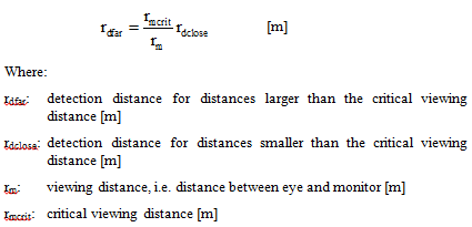
|
a0c0 |
| A10 2. | Secondary functional requirements | a0c0 |
| A10 | Based on the installation conditions, a determination shall be made to discover whether the entire device can still satisfy the functional requirements listed in paragraph 6.2.2. of this Regulation, specifically the glare correction, the maximum and the minimum luminance of the monitor. It shall also be determined the degree to which the glare correction will be addressed and the angle at which sunlight can strike a monitor and these shall be compared to the corresponding measuring results from the system measurements. This can be either based on a CAD-generated model, a determination of the angles of light for the device when mounted on the relevant vehicle, or by carrying out relevant measurements on the relevant vehicle as described in paragraph 6.2.2.2. of this Regulation. | a0c0 |
| A11 |
|
a0c0 |
| A11 |
|
a0c0 |
| A11 1. | Camera monitor device for indirect vision | a0c0 |
| A11 1.1. | General | a0c0 |
| A11 | Determination of the displayed object size considers the possible appearance of smear. The impact on the monitors image and consequence is the occultation of the field of view and therefore of the object. The following differentiation is made: | a0c0 |
| A11 1.2. | Case A: Smear appears | a0c0 |
| A11 1.2.1. | Step 1: Under the condition described in paragraph 6.2.2.2.1.2. of this Regulation, measure the width (s) of the vertical bar displayed on the monitor e.g. with a measurement microscope. | a0c0 |
| A11 1.2.2. | Step 2: Place the object at a defined distance from the camera. Measure the width of the object displayed on the monitor (b) in a situation without real sun light condition e.g. with a measurement microscope. | a0c0 |
| A11 1.2.3. | Step 3: Calculate the residual object width (a) according to the following equation: | a0c0 |
| A11 |
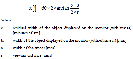
|
a0c0 |
| A11 1.3. | Case B: Smear does not appear | a0c0 |
| A11 1.3.1. | Step 1: Place the object at a defined distance from the camera. Measure the width of the object displayed on the monitor (b) in a situation without real sun light condition e.g. with a measurement microscope. | a0c0 |
| A11 1.3.2. | Step 2: Calculate the object width (a) according to the following equation: | a0c0 |
| A11 |

|
a0c0 |
| A11 1.4. | Data supplied by the instructions for use | a0c0 |
| A11 | In the case of Classes V and VI camera monitor devices the instructions for use shall include a table that shows the minimum and maximum mounting height of the camera above ground under consideration of different viewing distances. The camera shall be mounted within the applicable height range. The viewing distances shall be selected from the intended context of use. The following table shows an example. | a0c0 |
| A11 |
|
a0c0 |
| A11 1.4.1. | The value of the minimum mounting height is the same for all viewing distances as it is independent of the viewing distance. It is determined by the dimensions of the field of vision and the field of view of the camera. Use the following working steps for determination of the minimum mounting height. | a0c0 |
| A11 1.4.1.1. | Step 1: Draw the intended field of vision on ground. | a0c0 |
| A11 1.4.1.2 | Step 2: Place the camera above the field of vision in such a way that the camera is viewing the field of vision. The lateral position shall be in accordance with the intended mounting position at the vehicle. | a0c0 |
| A11 1.4.1.3. | Step 3: Change the height of the camera above ground in such a way, that the field of vision displayed on the monitor covers an area at least as large as the field of vision. Furthermore, the field of vision display shall encompass the entire monitor screen. | a0c0 |
| A11 1.4.1.4. | Step 4: Measure the height between camera and ground which is the minimum mounting height. Report the result value. | a0c0 |
| A11 1.4.2. | The value of the maximum mounting height is different for different viewing distances as the displayed object size varies with the mounting height. Use the following working steps for determination of the maximum mounting height: | a0c0 |
| A11 1.4.2.1. | Step 1: Determine the minimum width bmin of the critical object displayed on the monitor for each viewing distance. | a0c0 |
| A11 |
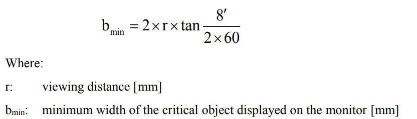
|
a0c0 |
| A11 1.4.2.2. | Step 2: Place the critical object inside the drawn intended field of vision in a position at which the distance between the critical object and the camera is largest. The illumination conditions shall be in such a way that the critical object is clearly visible on the monitor. | a0c0 |
| A11 1.4.2.3. | Step 3: Select the first value of the possible viewing distances. | a0c0 |
| A11 1.4.2.4. | Step 4: Change the height of the camera above ground in such a way, that the residual width B of the object displayed on the monitor is equal to the minimum width allocated to that viewing distance. | a0c0 |
| A11 |

|
a0c0 |
| A11 1.4.2.5. | Step 5: Measure the height between camera and ground which is the maximum mounting height allocated to that viewing distance. Report the result value. | a0c0 |
| A11 1.4.2.6. | Step 6: Repeat the aforementioned steps 4 and 5 for the other viewing distances. | a0c0 |
| A12 |
|
a0c0 |
| A12 |
|
a0c0 |
| A12 1. | Test methods | a0c0 |
| A12 1.1. | General specifications | a0c0 |
| A12 | The Technical Service shall use recognized test methods to check compliance with the requirements defined above in the Regulation. These test methods shall be agreed upon by the Type Approval Authority. | a0c0 |
| A12 1.2. | Flicker test | a0c0 |
| A12 | The entire image area of the monitor shall be free of flicker for at least 90 per cent of the user population. The flicker evaluation uses the determination given in Annex B of ISO13406-2: 2001. The following measurement procedure applies: | a0c0 |
| A12 1.2.1. | Position the camera of the CMS in front of a still scene (e.g. chessboard chart). Use a scene illumination of about 500 lx. Measure the time resolved luminance value of a portion of the monitor that displays a white patch of the chessboard chart. The measurement location shall be near the centre of the monitor defined size and the measurement direction is perpendicular onto the monitor. Perform a Fourier transform of the luminance-time function for determination of the amount of energy Eobs at various frequencies up to 120 Hz. These numbers are then compared to the amounts of energies that people will detect as flicker, the predicted flicker threshold Epred. | a0c0 |
| A12 | If Eobs < Epred at every frequency < 120 Hz then it is likely that people will not see flicker. | a0c0 |
| A12 | If Eobs ≥ Epred at any frequency < 120 Hz then it is likely that people will see flicker. | a0c0 |
| A12 1.2.2. | Determination of Eobs, which is the observed energy at every frequency < 120 Hz: | a0c0 |
| A12 |
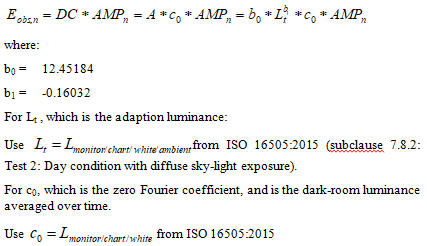
|
a0c0 |
| A12 |
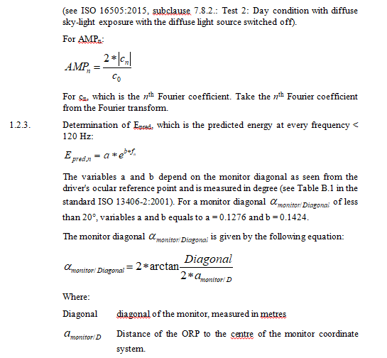
|
a0c0 |
| A12 1.2.4. | For every frequency < 120 Hz compare the observed energy Eobs with the predicted energy Epred and report the result value for passed or failed. | a0c0 |
| A12 1.3. | Point light sources test method | a0c0 |
| A12 | Figure 1 shows the test arrangement for the point light source test. | a0c0 |
| A12 | Figure 1 | a0c0 |
| A12 | Test arrangement for the point light source test | a0c0 |
| A12 |

|
a0c0 |
| A12 | The point light source lab model is an emulation of a set of vehicle passing beam headlamps at a distance of 250 m with luminous intensity of 1,750 cd, in accordance to the maximum allowance of luminous intensity of a vehicle passing-beam headlamp at point "BR" described in Regulation No. 112, 01 series of amendments. The test is performed considering a set of lamps with 0.09 m diameter and separated by 1.3 m. This results in a luminance of 275,000 cd/m2. For laboratory evaluation purposes the light sources shall be adjusted to have a luminance within the range of 250,000 to 300,000 cd/m2 by using a constant current source. | a0c0 |
| A12 | For laboratory evaluation purpose a shorter distance than 250 m can be used. | a0c0 |
| A12 | The distance aPLS from the camera entrance pupil to the point light source lab model shall be within the depth of field of the camera. The point light source lab model shall be adjusted to the measuring distance aPLS in terms of lamp size dPLS and distance SDPLS. The value for dPLS and SDPLS shall be rounded to the nearest 0.1 mm. | a0c0 |
| A12 | A typical white LED having a correlated colour temperature of 6,500 K with a tolerance of ± 1,500 K is used for this evaluation. The emitting surface of the LED shall keep an even luminance or it shall be diffused using an optional diffuser as shown in Figure 1. | a0c0 |
| A12 | The angular size corresponding to the headlamp of 0.09 m diameter and the angular orientation of the two point light source separated by 1.3 m of each other, at 250 m distance, are calculated as: | a0c0 |
| A12 |
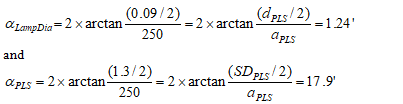
|
a0c0 |
| A12 | For example, at 6 m distance from CMS to this emulated LED, the corresponding aperture opening of the LED shall be dPLS = 2.2 mm in diameter and separated by SDPLS = 31.2 mm to emulate the set of passing beam headlamps located 250 m from the CMS. | a0c0 |
| A12 | Ambient illumination at the point light source lab model and at the monitor-side shall be less than 2 lx. | a0c0 |
| A12 | The luminance of the LED shall be measured at the same angular direction of the CMS to confirm that light emitted from the aperture delivers the correct luminance. | a0c0 |
| A12 | The luminance of the rendered point light sources on the monitor is measured by using a reference (luminance) camera according to ISO 16505:2015 providing a sufficient spatial resolution, or equivalent. | a0c0 |
| A12 | For the evaluation, the CMS shall be switched to the operation mode intended to observe the point light sources. | a0c0 |
| A12 | Position the camera of the CMS such that its optical axis is aligned to the perpendicular orientation of the point light source lab model (Figure 1). Target the CMS camera to display the point light sources in the middle of the monitor defined size. The distance from the camera entrance pupil to the point light source lab model shall be set to aPLS. | a0c0 |
| A12 | For determination of the point light source detection factor PLSDF evaluate the luminance profile in horizontal and vertical direction (Figure 2). | a0c0 |
| A12 | Figure 2 | a0c0 |
| A12 | Luminance profile of the rendered point light sources for the determination of PLSDF | a0c0 |
| A12 |

|
a0c0 |
| A12 | Verify the consistency of the result with slightly shifted position of the point light source lab model. | a0c0 |
| A12 | For determination of the point light source contrast factor PLSCF, evaluate the luminance profile in horizontal direction (Figure 3) at the vertical centre. | a0c0 |
| A12 | Figure 3 | a0c0 |
| A12 | Luminance profile of the rendered point light sources for the determination of the PLSCF | a0c0 |
| A12 |
|
a0c0 |
| A12 | Verify the consistency of the result with slightly shifted position of the point light source lab model. | a0c0 |
| A12 1.4. | Grey scale rendering test method | a0c0 |
| A12 | The grey scale rendering test shall verify that CMS are capable of displaying at least 8 tonal grey steps distinguishable within the darkest and brightest output range from the reproduced chart on the CMS monitor. The grey scale rendering test is evaluated using a 20:1 low contrast grey scale chart as described in ISO 14524:2009, Table A.1, under 500 lx illuminated scene environment. | a0c0 |
| A12 | The distinguishable tonal difference described herein is defined as an display output signal whose lightness difference between two different tonal input through the CMS satisfy at least delta L* ≥ 3.0, with L* defined as lightness according to the definition in CIE 1976 L*a*b* colour space. | a0c0 |
| A12 | Figure 4 shows the test arrangement for the grey scale rendering test. | a0c0 |
| A12 | Figure 4 | a0c0 |
| A12 | Test arrangement for the grey scale rendering test | a0c0 |
| A12 |
|
a0c0 |
| A12 | Figure 5 shows an example of a grey scale rendering chart to be used in this measurement. The grey scale rendering chart shall consists of 12 different tonal density grey patches. | a0c0 |
| A12 | The density value Di shall follow the values as defined by ISO 14524:2009 Table A.1 for low contrast 20:1. The definition of Di is given in the ISO 14524:2009. | a0c0 |
| A12 | The background of the patches shall be covered with a neutral grey colour having a density value Di of 0.54 ± 0.05. | a0c0 |
| A12 | Both reflective and transmissive charts with Lambertian characteristics can be used. | a0c0 |
| A12 | The whole camera image area shall be covered by the chart image. The grey scale rendering chart shall be placed in such a way so that the grey patches are visible in the centre of the monitor defined size. | a0c0 |
| A12 | Adjust the distance between the camera under test and the test chart to have individual patches of the chart displayed by at least 50 x 50 pixels on the monitor under test, whenever possible. For Class IV devices exhibiting high distortion and/or optical vignetting, a reduced size area may also be used to minimize the vignette effect on the measurement results. | a0c0 |
| A12 | The illumination shall be similar to the CIE D65 standard illuminant and have a correlated colour temperature of T = 6,500 K with a tolerance of ± 1,500 K. | a0c0 |
| A12 | The test is performed with a scene illumination of 500 lx (this test condition is equivalent to test condition for colour rendering as defined in ISO 16505:2015 clause 7.8.3), and at room temperature 22 °C ± 5 °C. | a0c0 |
| A12 | Ambient illumination at the monitor-side shall be ≤ 10 lx, and glare light source to the monitor shall be avoided. | a0c0 |
| A12 | Figure 5 | a0c0 |
| A12 | Example of the grey scale rendering chart | a0c0 |
| A12 |
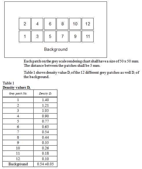
|
a0c0 |
| A12 |

|
a0c0 |
| A12 2. | Special requirements to be applied to the safety aspects of camera monitor systems for indirect vision | a0c0 |
| A12 2.1. | General | a0c0 |
| A12 | The purpose of this paragraph is to specify the requirements for documentation and verification for CMS for indirect vision of Classes I to IV to replace mandatory rear-view mirrors for road vehicles. | a0c0 |
| A12 | "The System", referred to herein, is the one for which type approval is being sought. | a0c0 |
| A12 | This paragraph 2. does not specify the performance criteria for "The System" but covers the methodology applied to the design process and the information which shall be disclosed to the Technical Service, for type approval purposes. | a0c0 |
| A12 | This information shall show that "The System" respects, under normal and fault conditions, all the appropriate performance requirements specified elsewhere in this Regulation. | a0c0 |
| A12 2.2. | Definitions | a0c0 |
| A12 2.2.1. | Camera Monitor System (CMS) | a0c0 |
| A12 | A CMS is used in road vehicles to present the required outside information of a specific field of view to the driver. It replaces a conventional legally prescribed mirror system on the vehicle by means of electronic image capture and display systems. | a0c0 |
| A12 | It consists of a camera that is usually installed at the bodywork of a vehicle and a monitor that is usually placed inside the vehicle. | a0c0 |
| A12 2.2.2. | Camera | a0c0 |
| A12 | A camera is a device to capture colour images of a specific field of view. It mainly consists of two relevant items: imager and lens. | a0c0 |
| A12 2.2.3. | Monitor | a0c0 |
| A12 | A monitor is a device for displaying images. It either consists of a matrix of active areas that radiate light of different wavelengths or is a (usually diffuse) reflector that is illuminated in different wavelengths and in a matrix of specific points by a projector. | a0c0 |
| A12 2.2.4. | Control unit | a0c0 |
| A12 | A control unit is a component which controls communication and coordination between electronic components, e.g. a camera and a monitor. | a0c0 |
| A12 2.2.5. | Safety concept | a0c0 |
| A12 | A safety concept is a description of the measures designed into the system, for example within the electronic units, so as to address system integrity and thereby ensure safe operation even in the event of a system or electrical failure. | a0c0 |
| A12 2.2.6. | "Boundary of functional operation" | a0c0 |
| A12 | "Boundary of functional operation" defines the boundaries of the external physical limits within which the system is able to maintain functionality. | a0c0 |
| A12 2.3. | Documentation | a0c0 |
| A12 2.3.1. | The vehicle manufacturer shall provide the following documentation: | a0c0 |
| A12 | a) A description of the camera monitor system which gives an explanation of the main function of the system, incl. drawings, pictures, block diagrams, etc. | a0c0 |
| A12 | b) A description of the location of the camera and the monitor in the vehicle (system overview). | a0c0 |
| A12 | c) Name of manufacturer of camera, monitor and electronic control units. | a0c0 |
| A12 | d) Type of camera and monitor. Each unit shall be clearly and unambiguously identifiable (e.g. by marking for hardware and marking or software output for software content) to provide corresponding hardware and documentation association. | a0c0 |
| A12 | e) Explanation of the warning strategy and the safety concept, as defined by the manufacturer, covering at least the list of failures of paragraph 2.4. | a0c0 |
| A12 2.3.2. | For periodic technical inspections, the documentation shall describe how the current operational status of "The System" can be verified. | a0c0 |
| A12 2.3.3. | The limits for the boundary of functional operation (e.g. environmental parameters) shall be stated where appropriate to the system performance. | a0c0 |
| A12 2.3.4. | Safety concept of the manufacturer | a0c0 |
| A12 | The manufacturer shall provide a statement which affirms that the strategy chosen allows a safe operation of "The System". | a0c0 |
| A12 | In the case of a failure, the driver shall be informed for example by a clear and visible warning signal or message display. When the system is activated, the warning shall be present as long as the fault condition persists. | a0c0 |
| A12 | The fault conditions shall be established and maintained by the manufacturer and shall be made open for inspection by the Technical Service at the time of the type approval. | a0c0 |
| A12 2.3.5. | The chosen analytical approach(es) shall be established and maintained by the manufacturer and shall be made open for inspection by the Technical Service at the time of the type approval. | a0c0 |
| A12 2.4. | List of failures | a0c0 |
| A12 2.4.1. | Camera | a0c0 |
| A12 | a) Failure of the camera; | a0c0 |
| A12 | b) Electronic noise, reduced detail resolution; | a0c0 |
| A12 | c) Defocus of the optics, reduced detail resolution. | a0c0 |
| A12 2.4.2. | Monitor | a0c0 |
| A12 | a) Failure of monitor display, no image content is displayed; | a0c0 |
| A12 | b) Freeze of displayed monitor content, image content is not refreshed; | a0c0 |
| A12 | c) Enlarged image formation time, changing image content is blurred. | a0c0 |
| A12 2.4.3. | Control unit | a0c0 |
| A12 | a) Failure of the control unit; | a0c0 |
| A12 | b) Failure in the communication between camera and control unit; | a0c0 |
| A12 | c) Failure in the communication between control unit and monitor. | a0c0 |
| A12 2.5. | Verification | a0c0 |
| A12 2.5.1. | Verification of the performance of the camera monitor system under no-fault and fault conditions shall be conducted against the manufacturer's specification. | a0c0 |
| A12 2.5.2. | The verification of the safety concept of the reaction of the camera monitor system shall, at the discretion of the Type Approval Authority, be verified according to the influence of failures in paragraph 2.4. The verification results shall correspond with the documented summary of the failure analysis in paragraph 2.4., to a level of overall effect such that the safety concept and execution are confirmed as being adequate. | a0c0 |
Regulation UN No. 46 (Rev.6)
Devices for indirect vision
Consolidated up to
Suppl.9 to 04
dated: 30.09.21.png)