| ... |
|
a0c0 | |||
| ... | Regulation | a0c0 | |||
| ... | Scope | a0c0 | |||
| ... | 2. Definitions | a0c0 | |||
| ... | 3. Application for approval | a0c0 | |||
| ... | 4. Markings | a0c0 | |||
| ... | 5. Approval | a0c0 | |||
| ... | 6. General specifications | a0c0 | |||
| ... | 7. Intensity of light emitted | a0c0 | |||
| ... | 8. Test procedure | a0c0 | |||
| ... | 9. Colour of light emitted | a0c0 | |||
| ... | 10. Conformity of production | a0c0 | |||
| ... | 11. Penalties for non-conformity of production | a0c0 | |||
| ... | 12. Production definitively discontinued | a0c0 | |||
| ... | 13. Names and addresses of Technical Services conducting approval tests, and of Type Approval Authorities | a0c0 | |||
| ... | 14. Transitional provisions | a0c0 | |||
| ... | Annexes | a0c0 | |||
| ... | 1 Minimum horizontal (H) and minimum vertical (V) angles for spatial light distribution | a0c0 | |||
| ... | 2 Communication | a0c0 | |||
| ... | 3 Examples of arrangements of the approval marks | a0c0 | |||
| ... | 4 Photometric measurements | a0c0 | |||
| ... | 5 Photometric measurements for the rear-registration-plate illuminating device | a0c0 | |||
| 1. |
|
a0c0 | |||
| ... | This Regulation applies to front position lamps, rear position lamps, stop lamps, direction indicators, and rear-registration-plate illuminating devices for vehicles of category L[1]. | a0c0 | |||
|
|
|
a0c0 | |||
| 2. |
|
a0c0 | |||
| 2.1. | Definitions of terms | a0c0 | |||
| ... | The definitions given in Regulations Nos. 53 or 74 and the series of amendments in force at the time of application for type approval shall apply to this Regulation. | a0c0 | |||
| 2.2. |
"Front position lamps, rear position lamps, stop lamps, direction indicator lamps and rear-registration-plate illuminating devices of different types" means lamps which differ |
a3c0 | |||
| ... | (a)The trade name or mark: | a3c0 | |||
| ... |
|
a3c0 | |||
| ... |
|
a3c0 | |||
| ... | (b)The characteristics of the optical system, (levels of intensity, light distribution angles, category of light source, light source module, etc.); | a0c0 | |||
| ... |
|
a2c0 | |||
| ... | A change of the colour of the light source or the colour of any filter does not constitute a change of type. | a0c0 | |||
| 2.3. |
The definitions of the colour of the light emitted, given in Regulation No. 48 and its series of amendments in force at the time of application for type approval shall apply to this Regulation. |
a0c0 | |||
| 2.4. |
References made in this Regulation to standard (étalon) filament lamp(s) and to Regulation No. 37 shall refer to Regulation No. 37 and its series of amendments in force at the time of application for type approval. |
a0c0 | |||
| ... |
References made in this Regulation to standard (étalon) LED light source(s) and to Regulation No. 128 shall refer to Regulation No. 128 and its series of amendments in force at the time of application for type approval. |
a0c0 | |||
| 3. |
|
a0c0 | |||
| 3.1. | The application for approval shall be submitted by the holder of the trade name or mark or by his duly accredited representative. It shall specify: | a0c0 | |||
| 3.1.1. | The purpose or purposes for which the device submitted for approval is intended; | a0c0 | |||
| 3.1.2. | In the case of a front position lamp an indication whether it is intended to emit white or amber light; | a0c0 | |||
| 3.1.3. | In the case of a direction indicator, the category; | a0c0 | |||
| 3.1.4. | At the choice of the applicant, that the device may be installed on the vehicle with different inclinations of the reference axis in respect to the vehicle reference planes and to the ground or rotate around its reference axis or, in the case of a rear registration plate lamp, that the device may be fitted in more than one or a field of positions in relation to the space to be occupied by the registration plate; these different conditions of installation (or different positions) shall be indicated in the communication form. | a0c0 | |||
| 3.2. | For each type of device, the application shall be accompanied by: | a0c0 | |||
| 3.2.1. |
Drawings, in triplicate, in sufficient detail to permit identification of the type of the device and showing the following: |
a1c0 | |||
| 3.2.2. | A brief technical description stating, in particular, with the exception of lamps with non-replaceable light sources: | a0c0 | |||
| ... |
(a)The category or categories of filament lamp(s) prescribed; this filament lamp category shall be one of those contained in Regulation No. 37 and its series of amendments in force at the time of application for type approval; and/or |
a0c0 | |||
| ... | (b)The category or categories of LED light source(s) prescribed; this LED light source category shall be one of those contained in Regulation No. 128 and its series of amendments in force at the time of application for type approval; and/or | a0c0 | |||
| ... | (c)The light source module specific identification code. | a0c0 | |||
| 3.2.3. | Two devices. | a0c0 | |||
|
|
|
a3c0 | |||
|
|
|
a3c0 | |||
|
|
|
a3c0 | |||
|
|
|
a3c0 | |||
| 4. |
|
a0c0 | |||
| 4.1. | Devices submitted for approval shall in a clearly legible and indelible way bear the following markings: | a0c0 | |||
| 4.1.1. | The trade name or market of the applicant; | a0c0 | |||
| 4.1.2. | With the exception of lamps with non-replaceable light sources, a clearly legible and indelible marking indicating: | a0c0 | |||
| ... | (a)The category or categories of light source(s) prescribed; and/or | a0c0 | |||
| ... | (b)The light source module specific identification code. | a0c0 | |||
| 4.2. | They shall comprise furthermore a space of sufficient size for the approval mark (see paragraph 3.2.1.). | a0c0 | |||
| 4.3. |
Lamps with non-replaceable light sources or light source module(s) shall bear the marking of the rated voltage or range of voltage. |
a3c0 | |||
| 4.4. | In the case of light source module(s) the light source module(s) shall bear: | a0c0 | |||
| 4.4.1. | The trade name or mark of the applicant; this marking must be clearly legible and indelible; | a0c0 | |||
| 4.4.2. |
The specific identification code of the module; this marking must be clearly legible and indelible. This specific identification code shall comprise the starting letters "MD" for "MODULE" followed by the approval marking without the circle as prescribed in paragraph 5.5.1. below and in the case several non-identical light source modules are used, followed by additional symbols or characters; this specific identification code shall be shown in the drawings mentioned in paragraph 3.2.1. above. |
a0c0 | |||
| ... | The approval marking does not have to be the same as the one on the lamp in which the module is used, but both markings shall be from the same applicant. | a0c0 | |||
| 4.4.3. |
The marking of the rated voltage |
a3c0 | |||
| 5. |
|
a0c0 | |||
| 5.1. |
If the two devices of a type of device which are submitted in pursuance of paragraph 3. above meet the requirements of this Regulation, approval shall be granted. |
a1c0 | |||
| 5.2. | When two or more lamps are part of the same device, approval is only granted, if each of these lamps satisfies the provisions of this Regulation or of another Regulation. Lamps not satisfying any one of those Regulations shall not be part of such device. | a0c0 | |||
| 5.3. | An approval number shall be assigned to each type approved. Its first two digits (at present 00 for the Regulation in its original form) shall indicate the series of amendments incorporating the most recent major technical amendments to the Regulation at the time of issue of the approval. The same Contracting Party may not assign the same number to another type of device covered by this Regulation. | a0c0 | |||
| 5.4. | Notice of approval or of refusal of approval of a type of device pursuant to this Regulation shall be communicated to the Parties to the Agreement applying this Regulation, by means of a form conforming to the model shown in Annex 2 to this Regulation and of an attached drawing supplied by the applicant for approval, in a format not exceeding A4 (210 x 297 mm) and, if possible, on a scale of 1:1. | a0c0 | |||
| 5.5. | Each device conforming to a type approved under this Regulation shall bear, in the space referred to in paragraph 4.2. above, in addition to the markings referred to in paragraphs 4.1. and 4.3. an international approval mark consisting of: | a0c0 | |||
| 5.5.1. | A circle enclosing the letter "E" followed by the distinguishing number of the country which was granted the approval[2], and | a0c0 | |||
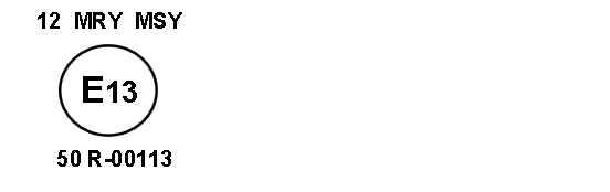
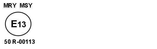
| 5.5.2. | The number of this Regulation followed by the letter "R", a dash and the approval number; | a0c0 | |||
| 5.5.3. |
In the general case of a direction indicator: a number indicating the category 11, 11a, 11b, 11c or 12 close to the circle according to paragraph 5.5.1. and on the opposite side to the approval number; |
a0c0 | |||
| 5.5.4 |
In the case of a direction indicator, which does on one side not attain the minimum luminous intensity prescribed up to an angle of H = 80° according to paragraph 7.7.1.: a horizontal arrow, the tip of which is oriented to the side where the minimum luminous intensity according to paragraph 7.7.1. is complied with up to an angle of at least 80°; |
a0c0 | |||
| 5.5.5. |
On front or rear position lamps of which the visibility angles are asymmetrical with regard to the reference axis in a horizontal direction, an arrow pointing towards the side on which the photometric specifications are met up to an angle of 80° H. |
a0c0 | |||
|
|
|
a1c0 | |||
|
|
(a) For a front position lamp "MAY"; (b) For a rear position lamp "MRY"; (c) For a stop lamp "MSY"." |
a1c0 | |||
| 5.6. | Where a device has been found to comply with the requirements of several Regulations, a single approval mark may be applied comprising a circle according to paragraph 5.5.1., the approval numbers and the additional symbols appropriate to each Regulation under which approval has been granted. The size of the components of this single approval mark shall not be less than the minimum size required for the smallest of the individual marks under a Regulation, under which approval has been granted. | a0c0 | |||
| 5.7. | The approval mark referred to in paragraph 5.5. above shall be clearly legible and be indelible. It may be placed on an inner or outer part (transparent or not) of the device emitting the light. In any case the marking shall be visible when the device is fitted on the vehicle or when a movable part such as the set or a compartment cover is opened. | a0c0 | |||
| 5.8. | Annex 3 gives an example of arrangement of the approval mark. | a0c0 | |||
|
|
|
a0c0 | |||
| 6. |
|
a0c0 | |||
| ... |
The requirements pertinent to each lamp and to the category/ies of vehicle on which the lamp is intended to be installed shall be applied, where its verification at the moment of lamp type approval is feasible. |
a3c0 | |||
| 6.1. | Each device shall conform to the specifications of this Regulation. | a0c0 | |||
| 6.2. | The devices must be so designed and constructed that in normal use and, despite the vibrations to which they may be subjected, their satisfactory operation continues to be assured and they retain the characteristics prescribed by this Regulation. | a0c0 | |||
| 6.3. | Position lamps, which are reciprocally incorporated with another function, using a common light source, and designed to operate permanently with an additional system to regulate the intensity of the light emitted, are permitted. | a0c0 | |||
| 6.3.1. | However, in the case of rear position lamp reciprocally incorporated with a stop lamp, the device shall either: | a0c0 | |||
| ... | (a)Be a part of a multiple light source arrangement, or | a0c0 | |||
| ... | (b)Be intended for use in a vehicle equipped with a failure monitoring system for that function. | a0c0 | |||
| ... | In either case, a note shall be made within the communication document. | a0c0 | |||
| 6.4. | In the case of replaceable light source(s): | a0c0 | |||
| 6.4.1. |
The device |
a4c0 | |||
| 6.4.2. | The design of the device shall be such that the light source cannot be fixed in any other position but the correct one. | a0c0 | |||
| 6.4.3. | The light source holder shall conform to the characteristics given in IEC Publication 60061. The holder data sheet relevant to the category of light source used, applies. | a0c0 | |||
| 6.5. | In the case of replaceable filament lamp(s): | a0c0 | |||
| 6.5.1. |
Any category or categories of filament lamp(s) approved according to Regulation No. 37 may be used, provided that no restriction on the use is made in Regulation No. 37 and its series of amendments in force at the time of application for type approval. |
a0c0 | |||
| 6.5.2. | The design of the device shall be such that the filament lamp can be fixed in no other position but the correct one. | a0c0 | |||
| 6.5.3. |
The filament lamp holder shall conform to the characteristics given in IEC Publication 60061. The holder data sheet relevant to the category of filament lamp used, applies. |
a0c0 | |||
|
|
|
a1c0 | |||
|
|
|
a3c0 | |||
|
|
|
a1c0 | |||
|
|
For direction indicator lamps of categories 11, 11a, 11b, 11c or 12 the flash may be produced by sequential activation of their light sources if the following conditions are met: (a) Each light source, after its activation, shall remain lit until the end of the ON cycle; (b) The sequence of activation of the light sources shall (c) (d) The variation shall finish no more than 200 ms after the beginning of the ON cycle; (e) For the orthogonal projection in the direction of the axis of reference of a rectangle, circumscribing the apparent surface of the direction indicator shall have its longer sides parallel to the H-plane, the ratio of the horizontal to the vertical sides shall not be less than 1.7. Compliance to the conditions mentioned above shall be verified in flashing mode. |
a4c0 | |||
| 7. |
|
a1c0 | |||
| ... | In the reference axis, the intensity of the emitted light of each of the two devices shall be at least equal to the minimum values and not exceed the maximum values of the following table. In no direction, the maximum values indicated shall be exceeded. | a1c0 | |||
| ... |
|
a1c0 | |||
| 7.1. |
|
a1c0 | |||
| 7.2. |
|
a1c0 | |||
| 7.2.1. |
|
a1c0 | |||
| 7.3. |
|
a1c0 | |||
| 7.4. |
|
a0c0 | |||
| 7.4.1. |
|
a1c0 | |||
| 7.4.1.1. |
|
a1c0 | |||
| 7.4.1.2. |
|
a1c0 | |||
| 7.4.1.3. |
|
a1c0 | |||
| 7.4.2. |
|
a1c0 | |||
| 7.5. |
Outside of the reference axis and within the angle fields defined in the diagrams in Annex 1 to this Regulation, the intensity of the light emitted shall, in each direction corresponding to the points in the light distribution table reproduced in Annex 4 to this Regulation, be not less than the product of the minima specified in paragraphs 5.7.1. to 7.4. above and of the percentage specified in the said table for the direction in question. |
a0c0 | |||
| 7.5.1. | In the case of a single lamp containing more than one light source: | a1c0 | |||
| ... |
(a) |
a1c0 | |||
| ... |
|
a1c0 | |||
| ... |
|
a1c0 | |||
| 7.6. |
As an exception to paragraph 7.1. above, a luminous intensity of 60 cd maximum shall be permitted for rear position lamps reciprocally incorporated with stop lamps below a plane forming an angle of 5° with and downward from a horizontal plane. |
a0c0 | |||
| 7.7. | Moreover, | a0c0 | |||
| 7.7.1. | Throughout the fields defined in Annex 1, the intensity of the light emitted shall not be less than 0.05 cd for position lamps and not less than 0.3 cd for stop lamps and direction indicators; | a0c0 | |||
| 7.7.2. |
If a position lamp is grouped or reciprocally incorporated with a stop lamp, the ratio between the luminous intensities actually measures of the two lamps when turned on simultaneously and the intensity of the rear position lamp when turned on alone shall be at least 5:1 to the eleven measuring points defined in Annex 4 and situated in the field delimited by straight vertical lines passing through 0°V/ 10°H and the straight horizontal lines passing through ±5°V/0°H of the light distribution table; |
a0c0 | |||
| ... | If the rear position lamp or the stop lamp or both contain more than one light source and are considered as a single lamp, as defined in paragraph 7.5.2. above, the values to be considered are those obtained with all light sources in operation. | a0c0 | |||
| 7.7.3. | The provisions of paragraph 2.2. of Annex 4 to this Regulation on local variations of intensity shall be observed. | a0c0 | |||
| 7.8. | In general the intensities shall be measured with the light sources(s) continuously alight. | a0c0 | |||
| ... | In the case of lamps intended to work intermittently, precaution shall be taken to avoid overheating of the device. Depending on the construction of the device, for example, the use of light-emitting diodes (LED) or the need to take precautions to avoid overheating, it is allowed to measure the lamps in flashing mode. | a0c0 | |||
| ... |
This must be achieved by switching with a frequency of f = 1.5 ± 0.5 Hz with the pulse width greater than 0.3 s, measured at 95 per cent peak light intensity. |
a0c0 | |||
| ... | In the case of replaceable filament lamps the filament lamps shall be operated at reference luminous flux during on time. In all other cases the voltage as required in paragraph 8.1. shall be switched with a rise time and fall time shorter than 0.01 s; no overshoot is allowed. | a0c0 | |||
| ... | In the case of measurements taken in flashing mode the reported luminous intensity shall be represented by the maximum intensity. | a0c0 | |||
| 7.9. | Annex 4, to which reference is made in paragraph 7.5. above, gives particulars of the methods of measurement to be used. | a0c0 | |||
| 7.10. | The rear-registration-plate illuminating device shall comply with the specifications indicated in Annex 5 to this Regulation. | a0c0 | |||
| 7.11. |
|
a1c0 | |||
| 7.11.1. |
|
a1c0 | |||
| 7.11.2. |
|
a1c0 | |||
| 8. |
|
a0c0 | |||
| 8.1. | All measurements, photometric and colorimetric shall be carried out with an uncoloured or coloured standard light source of the category prescribed for the device, supplied with the voltage: | a0c0 | |||
| ... | (a)In the case of filament lamps, that is necessary to produce the reference luminous flux required for that category of filament lamp; | a0c0 | |||
| ... |
(b)In the case of LED light sources of 6.75 V or 13.5 V; the luminous flux value produced shall be corrected. The correction factor is the ratio between the objective luminous flux and the mean value of the luminous flux found at the voltage applied; |
a0c0 | |||
| ... | (c)In the case of lamps with non-replaceable light sources: 6.75 V and 13.5 V respectively; | a0c0 | |||
| ... |
(d)In the case of a system that uses an electronic light source control gear being part of the lamp[3] applying at the input terminals of the lamp the voltage declared by the manufacturer or, if not indicated, 6.75 V, 13.5 V or 28.0 V, respectively; |
a0c0 | |||
| ... | (e)In the case of a system that uses an electronic light source control gear not being part of the lamp, the voltage declared by the manufacturer shall be applied to the input terminals of the lamp. | a0c0 | |||
| 8.2. | The test laboratory shall require from the manufacturer the light source control gear needed to supply the light source and the applicable functions. | a0c0 | |||
| 8.3. |
The voltage to be applied to the lamp shall be noted in the communication form in Annex 2 of this Regulation. |
a0c0 | |||
| 8.4. | The limits of the apparent surface in the direction of the reference axis of a light-signalling device shall be determined. | a0c0 | |||
|
|
|
a0c0 | |||
| 9. |
|
a0c0 | |||
| ... |
Stop lamps and rear position lamps shall emit red light, front position lamps may emit white or amber light, direction indicators shall emit amber light. For the measurement of the colour of the light emitted inside the field of the light distribution grid defined at paragraph 2. of Annex 4, the test procedure described in paragraph 8. of this Regulation shall be applied. Outside this field no sharp variation of colour shall be observed. |
a0c0 | |||
| ... | However, for lamps equipped with non-replaceable light sources (filament lamps and other), the colorimetric characteristics should be verified with the light sources present in the lamps, in accordance with relevant subparagraphs of paragraph 8.1. of this Regulation. | a0c0 | |||
| 10. |
|
a0c0 | |||
| 10.1. | Every device bearing an approval mark as prescribed under this Regulation shall conform to the type approved and shall comply with the requirements of this Regulation. However, in the case of a device picked at random from series production, the requirements as to the respectively, minimum and maximum intensities of the light emitted (measured with a standard light source as referred to in paragraph 8. above) shall be at least 80 per cent of the minimum values specified and not exceed 120 per cent of the maximum values allowed. | a0c0 | |||
|
|
|
a3c0 | |||
|
|
|
a3c0 | |||
|
|
|
a3c0 | |||
|
|
|
a3c0 | |||
|
|
|
a3c0 | |||
| 11. |
|
a0c0 | |||
| 11.1. | The approval granted in respect of a device pursuant to this Regulation may be withdrawn in the foregoing conditions are not observed. | a0c0 | |||
| 11.2. | If a Contracting Party to the Agreement, applying this Regulation, withdraws an approval it has previously granted, it shall forthwith so notify the other Contracting Parties applying this Regulation, by means of a copy of the approval form bearing at the end, in large letters, the signed and dated annotation "APPROVAL WITHDRAWN". | a0c0 | |||
| 12. |
|
a0c0 | |||
| ... | If the holder of the approval completely ceases to manufacture a device approved in accordance with this Regulation, he shall so inform the Type Approval Authority, which granted the approval. Upon receiving the relevant communication, that Authority shall inform thereof the other Parties to the Agreement which apply this Regulation by means of a copy of the approval form bearing at the end, in large letters, the signed and dated annotation "PRODUCTION DISCONTINUED". | a0c0 | |||
| 13. |
|
a0c0 | |||
| ... | The Contracting Parties to the Agreement which apply this Regulation shall communicate to the United Nations Secretariat the names and addresses of the Technical Services responsible for conducting approval tests and of the Type Approval Authorities which grant approval and to which forms certifying approval or refusal or withdrawal of approval issued in other countries are to be sent. | a0c0 | |||
| 14. |
|
a0c0 | |||
| 14.1. | Devices not equipped with filament lamps | a0c0 | |||
| 14.1.1. | As from the date of entry into force of Supplement 4 to this Regulation, no Contracting Party applying this Regulation shall refuse to grant approvals under this Regulation as amended by Supplement 4. | a0c0 | |||
| 14.1.2. | As from 36 months after the date of entry into force of Supplement 4 to this Regulation, Contracting Parties applying this Regulation shall grant approvals only if the type of devices as described in paragraph 14.1. above meets the requirements of this Regulation as amended by Supplement 4. | a0c0 | |||
| 14.1.3. | Contracting Parties applying this Regulation shall not refuse to grant extensions of approvals of this Regulation as amended by Supplement 3. | a0c0 | |||
| 14.1.4. | Contracting Parties applying this Regulation shall continue to grant approvals to those types of devices as described in paragraph 14.1. above, which comply with the requirements of this Regulation amended by Supplement 3 during the 36 months period which follows the date of entry into force of Supplement 4. | a0c0 | |||
| 14.2. | Fitting of devices described in paragraph 14.1. above on a vehicle. | a0c0 | |||
| 14.2.1. | As from the date of entry into force of Supplement 4 to this Regulation, no Contracting Party applying this Regulation shall prohibit the fitting on a vehicle of devices described in paragraph 14.1. above, approved to this Regulation as amended by Supplement 3, during the 48 months period which follows the date of entry into force of Supplement 4. | a0c0 | |||
| 14.2.2. | Contracting Parties applying this Regulation shall continue to allow the fitting on a vehicle of devices described in paragraph 14.1. above, approved to this Regulation as amended by Supplement 3, during the 48 months period which follows the date of entry into force of Supplement 4. | a0c0 | |||
| 14.2.3. | Upon the expiration of a period of 48 months after the date of entry into force of Supplement 4, Contracting Parties applying this Regulation may prohibit the fitting of devices, described in paragraph 14.1. above which do not meet the requirement of this Regulation as amended by Supplement 4, on a new vehicle for which type approval or individual approval was granted more than 24 months after the date of entry into force of Supplement 4. | a0c0 | |||
| 14.2.4. | Upon the expiration of a period of 60 months after the date of entry into force of Supplement 4, Contracting Parties applying this Regulation may prohibit the fitting of devices, as described in paragraph 14.1. above which do not meet the requirements of this Regulation, as amended by Supplement 4, on a new vehicle first registered more than 60 months after the date of entry into force of Supplement 4. | a0c0 | |||
|
|
|
a4c0 | |||
|
|
|
a4c0 | |||
|
|
|
a4c0 | |||
| A1 |
|
a0c0 | |||
| A1 |
|
a0c0 | |||
| A1 1. | Front position lamps | a1c0 | |||
| A1 |
V = +15° / -10° |
a1c0 | |||
| A1 |
|
a1c0 | |||
| A1 | Front position lamps (for a pair of lamps) | a1c0 | |||
| A1 |
V = +15° / -10° |
a1c0 | |||
| A1 |

|
a1c0 | |||
| A1 2. | Rear position lamps | a1c0 | |||
| A1 |
V = +15± / -10± |
a1c0 | |||
| A1 |

|
a1c0 | |||
| A1 | Rear position lamps (for a pair of lamps) | a1c0 | |||
| A1 |
V = +15° / -10° |
a1c0 | |||
| A1 |
|
a1c0 | |||
| A1 |
|
a1c0 | |||
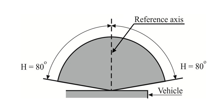
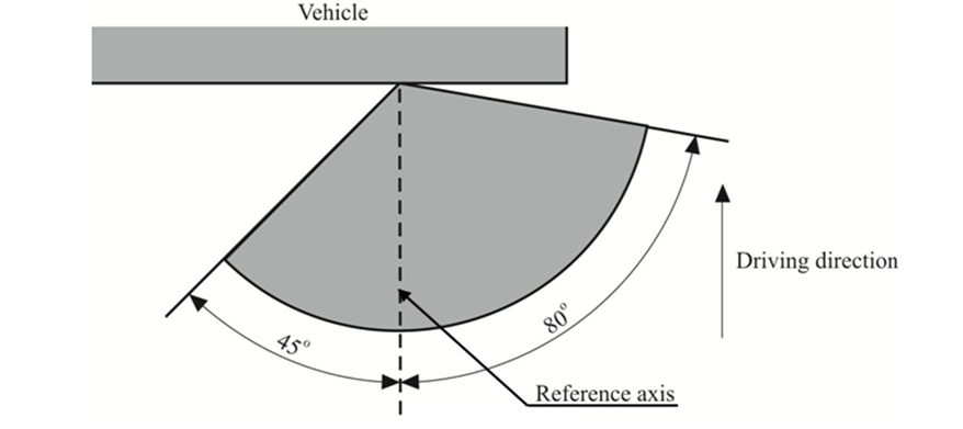
| A1 3. | Direction indicators of categories 11, 11a, 11b, 11c and 12 | a1c0 | |||
| A1 |
V = ±15° |
a1c0 | |||
| A1 | Minimum horizontal angles of light distribution in space: | a1c0 | |||
| A1 | Categories 11, 11a, 11b and 11c: | a1c0 | |||
| A1 | direction indicators for the front of the vehicle; | a1c0 | |||
| A1 | Category 11: | a1c0 | |||
| A1 | for use at a distance not less than 75 mm from the passing beam headlamp; | a1c0 | |||
| A1 | Category 11a: | a1c0 | |||
| A1 | for use at a distance not less than 40 mm from the passing beam headlamp; | a1c0 | |||
| A1 | Category 11b: | a1c0 | |||
| A1 | for use at a distance not less than 20 mm from the passing beam headlamp; | a1c0 | |||
| A1 | Category 11c: | a1c0 | |||
| A1 | for use at a distance less than 20 mm from the passing beam headlamp. | a1c0 | |||
| A1 |

|
a1c0 | |||
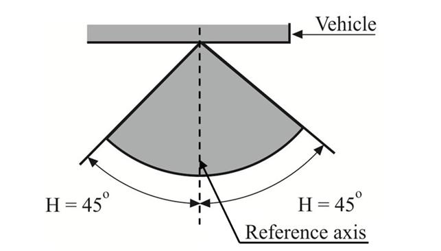
| A1 4. | Stop lamps | a1c0 | |||
| A1 |
V = + 15°/ -10° |
a1c0 | |||
| A1 |
|
a1c0 | |||
| A1 |
|
a1c0 | |||
| A2 |
|
a0c0 | |||
| A2 |
|
a0c0 | |||
| A2 | (Maximum format: A4 (210 x 297 mm)) | a0c0 | |||
| A2 |
|
a0c0 | |||
| A2 | of a type of front position lamps, rear position lamps, stop lamps, direction indicators and rear-registration-plate illuminating devices for mopeds, motor cycles and vehicles treated as such pursuant to Regulation No. 50 | a0c0 | |||
| A2 |
|
a0c0 | |||
| A2 1. | Trade name or mark of the device: | a0c0 | |||
| A2 2. | Manufacturer's name for the type of device: | a0c0 | |||
| A2 3. | Manufacturer's name and address: | a0c0 | |||
| A2 4. | If applicable, name and address of the manufacturer's representative: | a0c0 | |||
| A2 5. | Submitted for approval on: | a0c0 | |||
| A2 6. | Technical Service responsible for conducting approval tests: | a0c0 | |||
| A2 7. | Date of report issued by that Service | a0c0 | |||
| A2 8. | Number of report issued by that Service | a0c0 | |||
| A2 9. | Concise description[3]: | a0c0 | |||
| A2 | By category of lamp: | a0c0 | |||
| A2 | Colour of light emitted: red / white / amber[2] | a0c0 | |||
| A2 | Number and category(ies) of light source(s): | a0c0 | |||
| A2 | Light source module: yes/no[2] / | a0c0 | |||
| A2 | Light source module specific identification code: | a0c0 | |||
| A2 | Geometrical conditions of installation and relating variations, if any: | a0c0 | |||
| A2 | Application of an electronic light source control gear/variable intensity control: | a0c0 | |||
| A2 | (a)being part of the lamp: yes/no/not applicable[2] | a0c0 | |||
| A2 | (b)being not part of the lamp: yes/no/not applicable[2] | a0c0 | |||
| A2 | Input voltage(s) supplied by an electronic light source control gear/variable intensity control: | a0c0 | |||
| A2 | Electronic light source control gear/variable intensity control manufacturer and identification number (when the light source control gear is part of the lamp but is not included into the lamp body): | a0c0 | |||
| A2 |
|
a1c0 | |||
| A2 |
Front position lamp: yes/ no[2] Rear position lamp: yes/ no[2] Stop lamp: yes/ no [2] |
a1c0 | |||
| A2 |
|
a2c0 | |||
| A2 10. | Position of the approval mark: | a0c0 | |||
| A2 11. | Reason(s) for extension (if applicable): | a0c0 | |||
| A2 12. | Approval granted/extended refused withdrawn[2]: | a0c0 | |||
| A2 13. | Place: | a0c0 | |||
| A2 14. | Date: | a0c0 | |||
| A2 15. | Signature: | a0c0 | |||
| A2 16. | The list of documents deposited with the Type Approval Authority which has granted approval is annexed to this communication and may be obtained on request | a0c0 | |||
|
A2 |
|
a0c0 | |||
|
A2 |
|
a0c0 | |||
|
A2 |
|
a0c0 | |||
| A3 |
|
a0c0 | |||
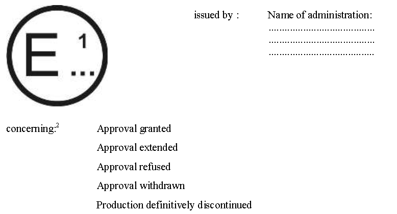
| A3 |
|
a1c0 | |||
| A3 | (See paragraph 5.3. of this Regulation) | a1c0 | |||
| A3 |

|
a1c0 | |||
| A3 | A device bearing the approval mark shown above is a direction indicator of the category 11 approved in the Netherlands (E4) under the number 00243. The first two digits of the approval number indicate that the approval was granted in accordance with the requirements of Regulation No. 50 in its original form. | a0c0 | |||
| A3 |
For a direction indicator, the arrow indicates that the luminous distribution is a symmetrical in a horizontal plane and that the photometric values required are satisfied up to an angle of 80° to the right, the device seen in the opposite sense of the light emitted. |
a1c0 | |||
| A3 | Light source modules | a0c0 | |||
| A3 |

|
a0c0 | |||
| A3 |
The light source module bearing the identification code shown above has been approved together with a lamp approved in Italy (E3) under approval number 17325. |
a0c0 | |||
| A3 | Note: The approval number must be placed close to the circle and either above or below the letter "E" or to the left of right of that letter the digits of the approval number must be on the same side of the "E" and face in the same direction. The use of Roman numbers as approval numbers should be avoided so as to prevent any confusion with other symbols. | a0c0 | |||
| A3 |
|
a1c0 | |||
| A3 |
|
a1c0 | |||
| A3 |
|
a1c0 | |||
| A3 |
|
a1c0 | |||
| A3 |
|
a1c0 | |||
| A3 |
|
a1c0 | |||
| A3 |
|
a1c0 | |||
| A3 |
|
a1c0 | |||
| A3 |
|
a1c0 | |||
| A4 |
|
a0c0 | |||
| A4 |
|
a0c0 | |||
| A4 1. | Measurement methods | a0c0 | |||
| A4 1.1. | During photometric measurements, stray reflections shall be prevented by appropriate masking. | a0c0 | |||
| A4 1.2. | Should the results of measurements be challenged, measurements shall be carried out in such a way as to meet the following requirements: | a0c0 | |||
| A4 1.2.1. | The distance of measurements shall be such that the law of the inverse of the square of the distance is applicable; | a0c0 | |||
| A4 1.2.2. |
The measuring equipment shall be such that the angular aperture of the receiver viewed from the reference centre of the lamp is between 10' and 1°; |
a0c0 | |||
| A4 1.2.3. | The intensity requirement for a particular direction of observation shall be deemed to be satisfied if that requirement is met in a direction deviating by not more than 15' from the direction of observation. | a0c0 | |||
| A4 1.3. | In the case where the device may be installed on the vehicle in more than one or in a field of different positions the photometric measurements shall be repeated for each position or for the extreme positions in the field of the reference axis specified by the manufacturer. | a0c0 | |||
| A4 2. | Standard luminous intensity distribution table | a0c0 | |||
| A4 |

|
a0c0 | |||
| A4 2.1. |
The direction H = 0° and V = 0° corresponds to the reference axis. (On the vehicle it is horizontal, parallel to the median longitudinal plane of the vehicle and oriented in the required direction of visibility). It passes through the centre of reference. The values shown in the table give, for the various directions of measurements, the minimum intensities as a percentage of the minimum required in the axis for each lamp (in the direction H = 0° and V = 0°). |
a0c0 | |||
| A4 2.2. | Within the field of light distribution of paragraph 2., schematically shown as a grid, the light pattern should be substantially uniform so that the light intensity in each direction of a part of the field formed by the grid lines meets at least the lowest minimum percentage value being shown on the grid lines surrounding the questioned direction. | a0c0 | |||
|
A4 |
|
a1c0 | |||
| A4 3. | Test conditions | a0c0 | |||
| A4 | The photometric performance shall be checked: | a0c0 | |||
| A4 3.1. | For non-replaceable light sources (filament lamps and others): | a0c0 | |||
| A4 | With the light sources present in the lamp, in accordance with the relevant subparagraph of paragraph 8.1. of this Regulation. | a0c0 | |||
| A4 3.2. | For replaceable light sources: | a0c0 | |||
| A4 |
When equipped with light sources at 6.75 V or 13.5 V, the luminous intensity values produced shall be corrected. |
a0c0 | |||
| A4 |
For filament lamps the correction factor is the ratio between the reference luminous flux and the mean value of the luminous flux found at the voltage applied (6.75 V or 13.5 V). |
a0c0 | |||
| A4 |
For LED light sources the correction factor is the ratio between the objective luminous flux and the mean value of the luminous flux found at the voltage applied (6.75 V or 13.5 V). |
a0c0 | |||
| A4 |
The actual luminous fluxes of each light source used shall not deviate more than ±5 per cent from the mean value. |
a0c0 | |||
| A4 | Alternatively and in case of filament lamps only, a standard filament lamp may be used in turn, in each of the individual positions, operated at its reference flux, the individual measurements in each position being added together. | a0c0 | |||
| A4 3.3. |
For any signalling lamps, except those equipped with filament lamps, the luminous intensities measured after one minute and after 30 minutes of operation shall comply with the minimum and maximum requirements; direction indicators shall be operated in the flashing mode (f =±1.5 Hz, duty factor 50 per cent). The luminous intensity distribution after one minute of operation can be calculated from the luminous intensity distribution after 30 minutes of operation by applying at each test point the ratio of luminous intensities measured at HV after one minute and after 30 minutes of operation. |
a0c0 | |||
| A5 |
|
a0c0 | |||
| A5 |
|
a0c0 | |||
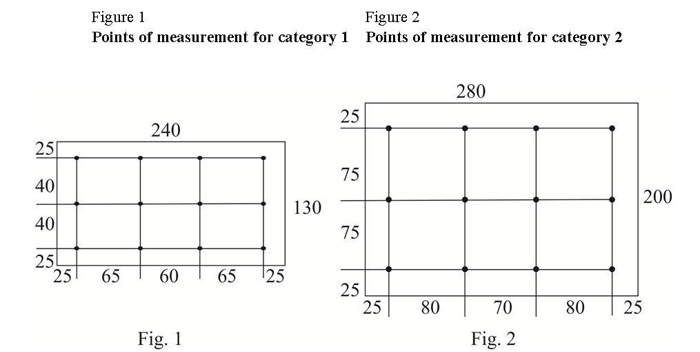
| A5 1. | Space to be illuminated | a0c0 | |||
| A5 | The devices can be of category 1 or 2. The devices of category 1 shall be designed to illuminate a space of at least 130 x 240 mm, the devices of category 2 shall be designed to illuminate a space of at least 200 x 280 mm. | a0c0 | |||
| A5 2. | Colour of the light | a0c0 | |||
| A5 | The light of the illuminating device shall be sufficiently colourless in order not to modify noticeably the colour of the rear-registration-plate. | a0c0 | |||
| A5 3. | Angle of incidence | a0c0 | |||
| A5 |
The manufacturer of the illuminating device shall specify one or more or a field of positions in which the device is to be fitted in relation to the space for the registration plate; when the lamp is placed in the position(s) specified by the manufacturer the angle of incidence of the light on the surface of the plate does not exceed 82° at any point of the surface to be illuminated, this angle being measured from the mid-point of the edge of the illuminating surface of the device which is furthest from the surface of the plate. If there is more than one illuminating device, the foregoing requirement shall apply only to the part of the plate intended to be illuminated by the device concerned. |
a0c0 | |||
| A5 | The device shall be so designed that no light is emitted directly towards the rear, with the exception of red light if the device is combined or grouped with a rear lamp. | a0c0 | |||
| A5 4. | Measuring procedure | a0c0 | |||
| A5 | Luminance measurements shall be made on a diffuse colourless surface with known diffuse reflection factor[1]. The diffuse colourless surface shall have the dimensions of the registration plate or the dimension exceeding one measuring point. Its centre shall be placed in the centre of the positions of the measuring points. | a0c0 | |||
| A5 | This diffuse colourless surface(s) shall be placed in the position normally occupied by the registration plate and 2 mm in front of its holder. | a0c0 | |||
| A5 |
Luminance measurements shall be made perpendicularly to the surface of the diffuse colourless surface with the tolerance of 5° in each direction at the points shown in paragraph 5. of this annex, each point representing a circular area of 25 mm in diameter. |
a0c0 | |||
| A5 | The measured luminance shall be corrected for the diffuse reflection factor 1.0. | a0c0 | |||
| A5 | For an illuminating device not equipped with filament lamps, the luminance values measured after one minute and after 30 minutes of operation shall comply with the minimum requirements. The luminance distribution after one minute of operation can be calculated from the luminance distribution after 30 minutes of operation, by applying at each test point the ratio of luminance values measured at one point after one minute and after 30 minutes of operation. | a0c0 | |||
|
A5 |
|
a0c0 | |||
| A5 5. | Photometric characteristics | a0c0 | |||
| A5 | At each of the points of measurement shown below, the luminance B shall be not less than 2 cd/m2. | a0c0 | |||
| A5 |
|
a0c0 | |||
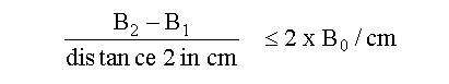
| A5 | The gradient of the luminance between the values B1 and B2, measured at any two points 1 and 2 selected from among those mentioned above, shall not exceed 2 x B0/cm, B0 being the minimum luminance measured at the various points, that is to say: | a0c0 | |||
| A5 |
|
a0c0 |