| ... | 1. Scope | a0c0 |
| ... | 2. Definitions | a0c0 |
| ... | 3. Application for approval | a0c0 |
| ... | 4. Markings | a0c0 |
| ... | 5. Approval | a0c0 |
| ... | 6. Specifications | a0c0 |
| ... | 7. Modifications of the type of pneumatic tyre and extension of approval | a0c0 |
| ... | 8. Conformity of production | a0c0 |
| ... | 9. Penalties for non-conformity of production | a0c0 |
| ... | 10. Production definitively discontinued | a0c0 |
| ... | 11. Names and addresses of Technical Services responsible for conducting approval tests of Type Approval Authorities | a0c0 |
| ... | 12. Transitional provisions | a0c0 |
| ... | Annexes | a0c0 |
| ... | 1. Communication | a0c0 |
| ... |
2. Arrangements of approval marks |
a6c0 |
| ... |
Appendix 1 - Example of separate Regulation No. 117 approval marks |
a6c0 |
| ... | a6c0 | |
| ... | a6c0 | |
| ... | Appendix 4 - Extensions to combine approvals issued in accordance with Regulation No. 117 | a0c0 |
| ... | 3. Coast-by test method for measuring tyre-rolling sound emission | a0c0 |
| ... | Appendix 1 - Test report | a0c0 |
| ... | 4. Specifications for the test site | a0c0 |
| ... | a6c0 | |
| ... | Appendix 1 - Test reports examples of wet grip index | a0c0 |
| ... | 6. Test procedure for measuring rolling resistance | a0c0 |
| ... | Appendix 1 -Test equipment tolerances | a0c0 |
| ... | a6c0 | |
| ... | Appendix 3 - Test report and test data (Rolling resistance) | a0c0 |
| ... | Appendix 4 -Tyre standards organizations | a0c0 |
| ... | Appendix 5 - Deceleration method: Measurements and data processing for deceleration value obtaining in differential form dω/dt | a0c0 |
| ... | 7. Procedures for snow performance testing relative to snow tyre for use in severe snow conditions | a0c0 |
| ... | a6c0 | |
| ... | Appendix 2 - Test reports and test data for C1 and C2 tyres | a0c0 |
| ... | Appendix 3 - Test reports and test data for C3 tyres | a0c0 |
| ... |
8. Procedures for ice performance testing relative to ice grip tyre of class C1 |
a6c0 |
| ... | a6c0 | |
| ... | a6c0 | |
| 1. |
|
a0c0 |
| 1.1. |
This Regulation applies to new pneumatic tyres |
a1c0 |
|
|
|
a1c0 |
| 1.1.1. | Tyres designed as "Temporary use spare tyres" and marked "Temporary use only"; | a0c0 |
| 1.1.2. | Tyres having a nominal rim diameter code ≤ 10 (or ≤ 254 mm) or ≥ 25 (or ≥ 635 mm); | a0c0 |
| 1.1.3. | Tyres designed for competitions; | a0c0 |
| 1.1.4. | Tyres intended to be fitted to road vehicles of categories other than M, N and O;[1] | a0c0 |
| 1.1.5. | Tyres fitted with additional devices to improve traction properties (e.g. studded tyres); | a0c0 |
| 1.1.6. |
Tyres with a speed |
a6c0 |
| 1.1.7. | Tyres designed only to be fitted to vehicles registered for the first time before 1 October 1990. | a0c0 |
| 1.1.8. | Professional off-road tyres. | a0c0 |
| 1.2. | Contracting Parties shall issue or accept approvals to rolling sound and/or wet adhesion and/or rolling resistance. | a0c0 |
|
|
|
a0c0 |
| 2. |
|
a0c0 |
| ... | For the purpose of this Regulation, in addition to the definitions contained in Regulations Nos. 30 and 54, the following definitions apply. | a0c0 |
| 2.1. |
"Type of tyre" means |
a2c0 |
| ... | (a) The manufacturer's name; | a0c0 |
| ... |
(b) The tyre class (see paragraph 2.6. below); |
a6c0 |
| ... | (c) The tyre structure; | a0c0 |
| ... | (d) The category of use: normal tyre, snow tyre and special use tyre; | a0c0 |
| ... | (e) Whether tyre for use in severe snow conditions or not; | a3c0 |
| ... |
(f) For class C1 tyres, whether ice grip tyre or not; |
a6c0 |
| ... | [DEL] | a3c0 |
| ... | [DEL] | a3c0 |
| ... |
(g) For Classes C2 and C3 tyres, whether traction tyre or not: |
a6c0 |
| ... | [DEL] | a3c0 |
| ... | [DEL] | a3c0 |
| ... |
(h) The tread pattern (see paragraph 3.2.1. of this Regulation). |
a6c0 |
| 2.2. |
|
a1c0 |
| 2.3. |
"Brand name/trademark" means the identification of the brand or trademark as defined by the tyre manufacturer and marked on the sidewall(s) of the tyre. The brand name/trademark may be the same as that of the Manufacturer. |
a6c0 |
|
|
|
a1c0 |
|
2. |
"Rolling sound emission" means the sound emitted from the contact between the tyres in motion and the road surface. | a1c0 |
|
2. |
"Tyre class" means one of the following groupings: | a1c0 |
|
2. |
Class C1 tyres: Tyres conforming to Regulation No. 30; | a1c0 |
|
2. |
Class C2 tyres: Tyres conforming to Regulation No. 54 and identified by a load capacity index in single formation lower or equal to 121 and a speed category symbol higher or equal to "N"; | a1c0 |
|
2. |
Class C3 tyres: Tyres conforming to Regulation No. 54 and identified by: | a1c0 |
| ... | (a) A load capacity index in single formation higher or equal to 122; or | a0c0 |
| ... | (b) A load capacity index in single formation lower or equal to 121 and a speed category symbol lower or equal to "M". | a0c0 |
| 2.7. |
"Representative tyre size" means the tyre size which is submitted to the test described in Annex 3 to this Regulation with regard to rolling sound emissions, or Annex 5 for adhesion on wet surfaces or Annex 6 for rolling resistance to assess the conformity for the type approval of the type of tyre, or Annex 7 for measuring snow performance, or Annex 8 for measuring ice performance." |
a6c0 |
|
2. |
"Temporary-use spare tyre" means a tyre different from a tyre intended to be fitted to any vehicle for normal driving conditions; but intended only for temporary use under restricted driving conditions. | a1c0 |
|
2. |
"Tyres designed for competition" means tyres intended to be fitted to vehicles involved in motor sport competition and not intended for non-competitive on-road use. | a1c0 |
|
2. |
"Normal tyre" means a tyre intended for normal on-road use. | a1c0 |
|
2. |
"Reinforced tyre" or "extra load tyre" of Class C1 means a |
a1c0 |
|
|
|
a0c0 |
|
2. |
"Traction tyre" means a tyre in Class C2 or C3 bearing the inscription TRACTION and intended to be fitted primarily to the drive axle(s) of a vehicle to maximize force transmission in various circumstances. | a1c0 |
|
2. |
"Snow tyre" means a tyre whose tread pattern, tread compound or structure is primarily designed to achieve in snow conditions a performance better than that of a normal tyre with regard to its ability to initiate or maintain vehicle motion. | a1c0 |
| 2.13.1. |
"Snow tyre for use in severe snow conditions" means a snow tyre whose tread pattern, tread compound or structure is specifically designed to be used in severe snow conditions and that fulfils the requirements of paragraphs 6.4. and 6.4.1. of this Regulation." |
a6c0 |
|
|
"Ice grip tyre" means a class C1 snow tyre for use in severe snow conditions that is additionally designed to be used on road surfaces covered with ice and that fulfils the requirements of paragraph 6.4.2. of this Regulation." |
a6c0 |
|
2. |
"Special use tyre" means a tyre intended for mixed use both on- and off-road or for other special duty. These tyres are primarily designed to initiate and maintain the vehicle in motion in off-road conditions. | a1c0 |
|
2. |
"Professional off-road tyre" is a special use tyre primarily used for service in severe off-road conditions. | a1c0 |
|
2. |
"Tread depth" means the depth of the principal grooves. | a1c0 |
|
2. |
"Principal grooves" means the wide circumferential grooves positioned in the central zone of the tyre tread, which, in the case of passenger and light truck (commercial) tyres, have the treadwear indicators located in the base. | a1c0 |
|
2. |
"Void to fill ratio" means the ratio between the area of voids in a reference surface and the area of this reference surface calculated from the mould drawing. | a1c0 |
| 2.18. |
"Standard Reference Test Tyre" |
a5c0 |
| ... |
(a) E1136 - 17 [DEL] for the size P195/75R14 and referred to as "SRTT14", |
a3c0 |
| ... |
(b) F2493 – 20 for the size P225/60R16 and referred to as "SRTT16", |
a6c0 |
| ... |
(c) F2872 – 16 for the size 225/75R16C and referred to as "SRTT16C", |
a6c0 |
| ... |
(d) F2871 – 16 for the size 245/70R19.5 and referred to as "SRTT19.5", |
a6c0 |
| ... |
(e) F2870 – 16 for the size 315/70R22.5 and referred to as "SRTT22.5". |
a6c0 |
| 2.19. |
Wet grip or snow DEL performance or ice performance measurements - Specific definitions |
a6c0 |
| 2.19.1. |
"Adhesion on wet surfaces" or "wet adhesion" means the relative braking performance, on a wet surface, of a test vehicle equipped with the candidate tyre in comparison to that of the same test vehicle equipped with a Standard Reference Test Tyre (SRTT). |
a6c0 |
| 2.19.2. |
"Candidate tyre" or "candidate tyre set" means a tyre or a tyre set, representative of the type that is submitted for approval in accordance with this Regulation and whose performances are evaluated relative to that of a reference tyre or reference tyre set. |
a6c0 |
|
|
"Reference tyre" or "reference tyre set" means a tyre or a tyre set of Standard Reference Test Tyres as defined in the respective annex. |
a6c0 |
|
2.19. |
"Control tyre" or "control tyre set" means a normal production tyre or a normal production tyre set that is used to establish the wet DEL adhesion level or snow DEL performance level or ice performance level of tyre sizes unable to be fitted to the same vehicle as the DEL reference tyre or reference tyre set – see paragraph 2.2.2.8. of Annex 5, part (B), paragraph 3.4.3. of Annex 7 and paragraph 2.4.5.1.1. of Annex 8 to this Regulation. |
a6c0 |
|
|
"Test tyre" means a candidate tyre, reference tyre or control tyre. |
a6c0 |
|
2.19. |
"Wet grip index" (G) means the dimensionless unit for expressing the wet adhesion level of a candidate tyre relative to that of the applicable DEL SRTT." |
a6c0 |
|
2.19. |
"Snow grip index" (SG) means the dimensionless unit for expressing the snow DEL performance level of a candidate tyre relative to the performance of the applicable SRTT." |
a6c0 |
|
|
"Ice grip index" (GI) means the dimensionless unit for expressing the ice performance level of a candidate tyre relative to the performance of the applicable SRTT. |
a6c0 |
|
2.19. |
"Peak brake force coefficient ("pbfc")" means the maximum value of the ratio of braking force to vertical load on the tyre prior to wheel lock-up. |
a6c0 |
|
2.19. |
"Mean fully developed deceleration ("mfdd")" means the average deceleration calculated on the basis of the measured distance recorded when decelerating a vehicle between two specified speeds. |
a6c0 |
|
2.19. |
"Coupling (hitch) height" means the height when measured perpendicularly from the centre of the articulation point of the trailer towing coupling or hitch to the ground, when the towing vehicle and trailer are coupled together. The vehicle and trailer shall be standing on level pavement surface in its test mode complete with the appropriate tyre(s) to be used in the particular test. |
a6c0 |
|
|
"Test run" means a single pass of a loaded tyre over a given test surface. |
a6c0 |
|
|
"Braking test" means a series of a specified number of test runs of the same test tyre repeated within a short time frame. |
a6c0 |
|
|
"Traction test" means a series of a specified number of spin-traction test runs of the same tyre repeated within a short time frame. |
a6c0 |
|
|
"Acceleration test" means a series of specified number of traction controlled acceleration test runs of the same tyre repeated within a short timeframe. |
a6c0 |
|
|
"Test cycle" means a series of braking tests, traction tests or acceleration tests that consist of an initial test of the reference tyre or the control tyre, of tests of candidate tyres and/or control tyres and a final test of the same reference tyre or control tyre." |
a6c0 |
|
2. |
Rolling resistance measurement - Specific definitions | a1c0 |
| 2.20.1. |
"Rolling resistance (Fr)" |
a6c0 |
| ... | means the loss of energy (or energy consumed) per unit of distance traveled.[3] | a3c0 |
|
|
|
a0c0 |
| 2.20.2. |
Rolling resistance coefficient (Cr) |
a6c0 |
| ... |
Means the ratio of the rolling resistance to the load on the tyre.[4] |
a6c0 |
|
|
|
a0c0 |
| 2.20.3. | "New test tyre" | a3c0 |
| ... |
means a tyre which has not been previously used in a rolling deflected test [DEL] which elevates the tyre's temperature to higher than that generated in rolling resistance tests, and which has not previously been exposed to a temperature above 40 ºC.[5], [6] |
a3c0 |
|
|
|
a0c0 |
|
|
|
a0c0 |
|
2. |
Laboratory control tyre | a1c0 |
| ... |
Means a tyre used by an individual laboratory to control machine behaviour as a function of time.[7] |
a6c0 |
|
|
|
a0c0 |
| 2.20.5. | "Capped inflation" | a3c0 |
| ... | means the process of inflating the tyre to the required cold inflation pressure and allowing the inflation pressure to build up, as the tyre is warmed up while running. | a3c0 |
|
2. |
Parasitic loss | a1c0 |
| ... |
Means the loss of energy (or energy consumed) per unit distance excluding internal tyre losses, attributable to aerodynamic loss of the different rotating elements of the test equipment, bearing friction and other sources of systematic loss which may be inherent in the measurement. |
a6c0 |
|
2. |
Skim test reading | a1c0 |
| ... |
Means a type of parasitic loss measurement, in which the tyre is kept rolling without slippage, while reducing the tyre load to a level at which energy loss within the tyre itself is virtually zero. |
a6c0 |
| 2.20.8. | "Inertia" or "moment of inertia" | a3c0 |
| ... | means the ratio of the torque applied to a rotating body, such as a tyre assembly or machine drum, to the rotational acceleration of this body.[8] | a3c0 |
|
|
|
a0c0 |
| 2.20.9. |
Measurement reproducibility (σm) |
a6c0 |
| ... |
Means the capability of a machine to measure rolling resistance.[9] |
a6c0 |
|
|
|
a0c0 |
| ... |

|
a0c0 |
| ... |
|
a0c0 |
| ... |
|
a0c0 |
| ... |
|
a0c0 |
| 3. |
|
a0c0 |
| 3.1. | The application for approval of a type of tyre with regard to this Regulation shall be submitted by the tyre manufacturer or by his duly accredited representative. It shall specify: | a0c0 |
| 3.1.1. |
The performance characteristics to be assessed for the type of tyre; "rolling sound emissions level" and/or "adhesion performance level on wet surfaces" and/or "rolling resistance level"; "snow performance level" in case of "snow tyre for use in severe snow conditions" and additionally "ice performance level" in case of ice grip tyre;" |
a6c0 |
| 3.1.2. |
Manufacturer's name and address; |
a3c0 |
| 3.1.3. |
If applicable, name and address of [DEL] manufacturer's representative; |
a3c0 |
|
3.1. |
Tyre class (Class C1, C2 or C3) (see paragraph 2.6. of this Regulation); |
a3c0 |
|
3.1. |
Category of use (normal, snow, or special); |
a3c0 |
| 3.1.5.1. |
Whether snow tyre for use in severe snow conditions or not; |
a6c0 |
| 3.1.5.2. |
For classes C2 and C3 tyres, whether traction tyre or not; |
a6c0 |
|
|
For class C1 tyres, whether ice grip tyre or not; |
a6c0 |
|
3.1. |
Tyre structure; |
a3c0 |
|
3.1. |
Brand name(s)/trademark(s), trade description(s)/commercial name(s); |
a3c0 |
|
3.1. |
A list of tyre size designations covered by this application and specifying for each brand name/trademark and/or each trade description/commercial name the applicable tyre size designations and service descriptions, adding in case of Class C1 tyres whether "reinforced" (or "extra load") or not. |
a3c0 |
|
|
[DEL] |
a3c0 |
|
|
[DEL] |
a3c0 |
|
|
[DEL] |
a3c0 |
|
|
[DEL] |
a3c0 |
| ... |
[DEL] |
a3c0 |
| ... |
[DEL] |
a3c0 |
| ... |
[DEL] |
a3c0 |
| ... |
[DEL] |
a3c0 |
| ... |
[DEL] |
a3c0 |
| 3.2. | The application for approval shall be accompanied (in triplicate) by: | a0c0 |
| 3.2.1. |
Details of the major features, with respect to the effects on the performance (i.e. rolling sound emission level, adhesion on wet surfaces, rolling resistance, snow performance and ice performance) of the tyres, including the tread pattern, included in the designated range of tyre sizes. This may be by means of descriptions supplemented by technical data, drawings, photographs or Computer Tomography (CT) scans, and must be sufficient to allow the Type Approval Authority or Technical Service to determine whether any subsequent changes to the major features will adversely affect the tyre performance. The effects of changes to minor details of tyre construction on tyre performances will be evident and determined during checks on conformity of production; |
a6c0 |
| 3.2.2. |
Drawings or photographs of the tyre sidewall, showing the DEL approval marks referred to in paragraph 4., shall be submitted once the production has been established, but no later than one year after the date of granting of type approval; |
a6c0 |
| 3.2.3. | In the case of applications relating to special use tyres, a copy of the mould drawing of the tread pattern shall be supplied in order to allow verification of the void-to-fill ratio. | a0c0 |
| 3.3. | At the request of the Type Approval Authority, the applicant shall submit samples of tyres for test or copies of test reports from the Technical Services, communicated as given in paragraph 11. of this Regulation. | a0c0 |
| 3.4. |
With regard to the application, testing may be confined to a [DEL] representative tyre size of the type of tyre, at the discretion of the Type Approval Authority [DEL]. |
a3c0 |
|
|
|
a1c0 |
| 4. |
|
a0c0 |
| 4.1. | All tyres constituting the type of tyre shall be marked as prescribed by either Regulation No. 30 or 54, as applicable. | a0c0 |
| 4.2. | In particular tyres shall bear:[10] | a0c0 |
| 4.2.1. |
The manufacturer's name or |
a1c0 |
|
|
|
a0c0 |
| 4.2.2. |
The trade description/commercial name (see paragraph 2.4. of this Regulation). However, the trade description is not required when it coincides with the brand name/trademark; |
a6c0 |
| 4.2.3. | The tyre size designation; | a0c0 |
| 4.2.4. | The inscription "REINFORCED" (or alternatively "EXTRA LOAD") if the tyre is classified as reinforced; | a0c0 |
| 4.2.5. | The inscription "TRACTION"[11] if the tyre is classified as "traction tyre"; | a0c0 |
|
|
|
a0c0 |
| 4.2.6. |
The "Alpine Symbol" ("3-peak-mountain with snowflake" conforming to the pictogram described in Annex 7, Appendix 1) DEL if the snow tyre is classified as "snow tyre for use in severe snow conditions"; |
a6c0 |
|
|
The "Ice Grip Symbol" (conforming to the pictogram described in Annex 8, Appendix 1) if the snow tyre for use in severe snow conditions is additionally classified as ice grip tyre; |
a6c0 |
| 4.2.7. | The inscription "MPT" (or alternatively "ML" or "ET") and /or "POR" if the tyre is classified in the category of use "special". | a0c0 |
| ... | ET means Extra Tread, ML stands for Mining and Logging, MPT means Multi-Purpose Truck and POR means Professional Off-Road. | a0c0 |
| 4.3. | Tyres shall provide adequate space for the approval mark as shown in Annex 2 to this Regulation. | a0c0 |
| 4.3.1. |
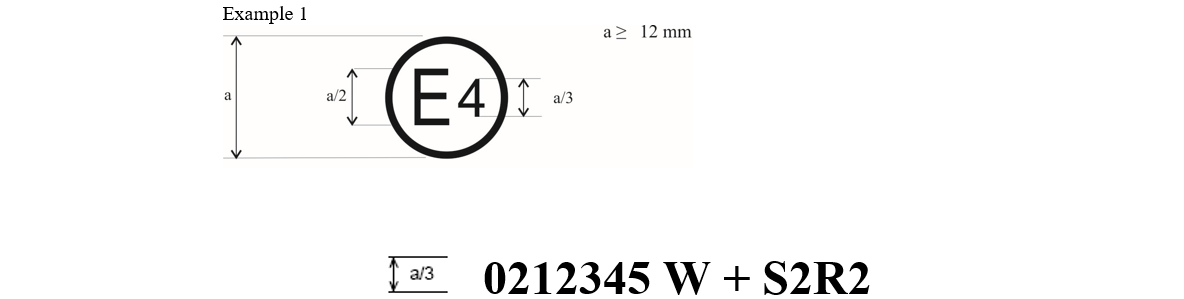
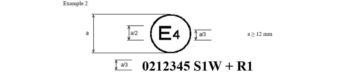
In case the approval of a tyre pursuant to this Regulation has been granted by the same Type Approval Authority than that granting the approval pursuant to UN Regulations Nos. 30 or 54, the approval mark pursuant to UN Regulations Nos. 30 or 54 can be combined with an indication of the applicable series of amendments to which the tyre was approved pursuant to UN Regulation No. 117 on the form of 2 digits (example "02" indicating that the UN Regulation No.117 approval was granted following the 02 series of amendments) and the suffixes according to paragraph 5.2.2. using the addition sign "+", as described in Annex 2, Appendix 3 of this Regulation, for example "0236378 + 02S1WR2". |
a6c0 |
| 4.4. |
|
a5c0 |
| 4.4.1. |
|
a5c0 |
| 5. |
|
a0c0 |
| 5.1. | If the representative tyre size of the type of tyre submitted for approval pursuant to this Regulation meets the requirements of paragraphs 6. and 7. below, approval of that type of tyre shall be granted. | a0c0 |
| 5.2. |
An approval number |
a2c0 |
|
|
Instead of granting the original type approval number pursuant to UN Regulation No. 117, upon the request of the manufacturer, the Type Approval Authority may grant the type approval number, which had been granted before to that type of tyre pursuant to UN Regulations Nos. 30 or 54 with the subsequent extension number. | a2c0 |
|
|
The communication form mentioned in paragraph 5.3. below shall identify specific performance parameters of UN Regulation No. 117 by the following suffixes: S To identify additional conformity to the requirements on tyre rolling sound emissions; W To identify additional conformity to the requirements on tyre adhesion on wet surfaces; R To identify additional conformity to the requirements on tyre rolling resistance. | a2c0 |
| ... | Taking into account that two stages are defined for rolling sound and rolling resistance specifications in paragraphs 6.1. and 6.3. below, S and R will be followed either by the suffix "1" for compliance to stage 1 or by the suffix "2" for compliance to stage 2. | a2c0 |
| 5.3. | Notice of approval or extension of approval or refusal of approval of a type of tyre pursuant to this Regulation shall be communicated to the Parties to the Agreement, which apply this Regulation by means of a form conforming to the model in Annex 1 to the Regulation. | a0c0 |
| 5.3.1. |
|
a2c0 |
| 5.3.1.1. |
When extension of approval is granted to incorporate into the communication form (see Annex 1 to this Regulation) certification(s) of conformity to other Regulations, (all) the specific type approval number(s) and the Regulation itself shall be added to item 9. of Annex 1 "Communication" DEL. |
a6c0 |
| 5.3.1.2. |
The suffix(es) mentioned in paragraph 5.2.2. above shall be preceded by the two digits identifying the series of amendments of the prescription on tyre performances for UN Regulation No. 117, e.g. "02S2" to identify the second series of amendments on tyre road rolling sound emissions at stage 2 or "02S1WR1" to identify the second series of amendments on tyre road rolling sound emissions at stage 1, tyre adhesion on wet surfaces and rolling resistance at stage 1 (see paragraph 6.1. below for stage 1 and stage 2 definitions). |
a6c0 |
| 5.3.2. | The following suffixes have been already reserved to identify specific Regulations on tyre performance parameters: | a0c0 |
| ... | S To identify additional conformity to the requirements on tyre rolling sound emissions; | a0c0 |
| ... | W To identify additional conformity to the requirements on tyre adhesion on wet surfaces; | a0c0 |
| ... | R To identify additional conformity to the requirements on tyre rolling resistance. | a0c0 |
| ... | Taking into account that two stages are defined for rolling sound and rolling resistance specifications in paragraphs 6.1. and 6.3. below, S and R will be followed either by the suffix "1" for compliance to stage 1 or by the suffix "2" for compliance to stage 2. | a0c0 |
| 5.4. | In the space referred to in paragraph 4.3. and in accordance with the requirements of paragraph 4.4. above there shall be affixed to every tyre size, conforming to the type of tyre approved under this Regulation, an international approval mark consisting of: | a0c0 |
| 5.4.1. | A circle surrounding the letter "E" followed by the distinguishing number of the country which has granted approval;[12] and | a0c0 |
|
|
|
a0c0 |
| 5.4.2. |
The |
a2c0 |
| 5.4.3. | The suffix(es), and the identification to the relevant series of amendments, if any, as specified in the communication form. | a0c0 |
| ... | One of the suffixes listed below or any combination of them can be used. | a0c0 |
| ... |
|
a6c0 |
| ... | These suffixes shall be placed to the right or below the approval number, if part of the original approval. | a0c0 |
| ... |
If the approval is extended subsequent to Regulation Nos. 30 or 54 approvals, the addition sign "+" and the series of amendment to Regulation No. 117 shall be placed in front of the suffix or any combination of suffixes to denote an extension to the approval. |
a6c0 |
| ... |
If the approval is extended subsequent to the original approval under UN Regulation No. 117, the addition sign "+" shall be placed between the suffix or any combination of suffixes of the original approval and the suffix or any combination of suffixes added to denote an extension to the approval. |
a6c0 |
| 5.4.4. |
The marking on the tyre sidewalls of suffix(es) to the approval number removes the requirement for any additional marking on the tyre of the specific type approval number for conformity to the Regulation(s) to which the suffix refers as per paragraph 5.<mod>2</mod>.2. above. |
a5c0 |
| 5.5. | If the tyre conforms to type approvals under one or more other Regulations annexed to the Agreement in the country which has granted approval under this Regulation, the symbol prescribed in paragraph 5.4.1. above need not be repeated. In such a case the additional numbers and symbols of all the Regulations under which approval has been granted in the country which has granted approval under this Regulation shall be placed adjacent to the symbol prescribed in paragraph 5.4.1. above. | a0c0 |
| 5.6. | Annex 2 to this Regulation gives examples of arrangements of approval marks. | a0c0 |
| 6. |
|
a0c0 |
| 6.1. | Rolling sound emission limits, as measured by the method described in Annex 3 to this Regulation. | a0c0 |
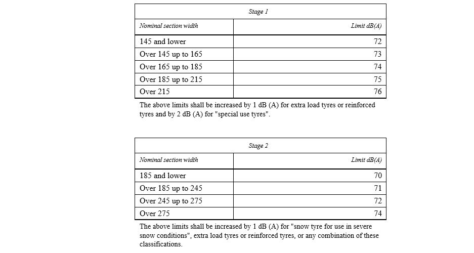
| 6.1.1. |
For Class C1 tyres, the rolling sound emission value shall not exceed the values pertinent to the applicable stage given below. These values refer to the nominal section width as DEL defined in UN Regulation No. 30: |
a6c0 |
| ... |
|
a0c0 |
| 6.1.2. |
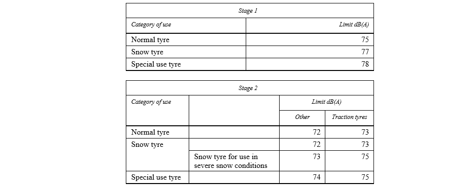
For class C2 tyres, the rolling sound emission value with reference to its category of use (see paragraph 2.1., subparagraph (d) above) shall not exceed the values pertinent to the applicable stage given below: |
a6c0 |
| ... |
|
a0c0 |
| 6.1.3. |
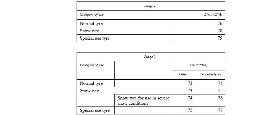
For class C3 tyres, the rolling sound emission value with reference to its category of use (see paragraph 2.1., subparagraph (d) above) shall not exceed the values pertinent to the applicable stage given below: |
a6c0 |
| ... |
|
a0c0 |
| 6.2. |
The wet DEL adhesion will be based on a procedure that compares either peak brake force coefficient ("pbfc") or mean fully developed deceleration ("mfdd") against values achieved by a Standard Reference Test Tyre (SRTT). The relative performance shall be indicated by a wet grip index (G). |
a6c0 |
| 6.2.1. |
For class C1 tyres, tested in accordance with either procedure given in Annex 5, Part (A), to this Regulation, the tyre shall meet the following requirements: |
a6c0 |
| ... |
|
a0c0 |
| 6.2.2. |
For class C2 tyres, tested in accordance with either procedure given in Annex 5, Part (B), to this Regulation, the tyre shall meet the following requirements: |
a6c0 |
| ... |

|
a0c0 |
| 6.2.3. |
For class C3 tyres, tested in accordance with either procedure given in Annex 5, Part (B), to this Regulation, the tyre shall meet the following requirements: |
a6c0 |
| ... |

|
a0c0 |
| 6.3. | Rolling resistance coefficient limits, as measured by the method described in Annex 6 to this Regulation. | a0c0 |
| 6.3.1. | The maximum values for stage 1 for the rolling resistance coefficient shall not exceed the following (value in N/kN is equivalent to value in kg/tonne): | a0c0 |
| ... |

|
a0c0 |
| ... | For "snow tyre for use in severe snow conditions", the limits shall be increased by 1 N/kN. | a0c0 |
| 6.3.2. | The maximum values for stage 2 for the rolling resistance coefficient shall not exceed the following (value in N/kN is equivalent to value in kg/tonne): | a0c0 |
| ... |

|
a0c0 |
| ... | For "snow tyre for use in severe snow conditions , the limits shall be increased by 1 N/kN. | a0c0 |
| 6.4. | In order to be classified as a "snow tyre for use in severe snow conditions" the tyre shall meet the performance requirements of paragraph 6.4.1. below. The tyre shall meet these requirements based on a test method of Annex 7 by which: | a0c0 |
| ... | (a) The mean fully developed deceleration ("mfdd") in a braking test, | a0c0 |
| ... | (b) Or alternatively an average traction force in a traction test, | a0c0 |
| ... | (c) Or alternatively the average acceleration in an acceleration test | a0c0 |
| ... |
of the candidate tyre is compared to that of a Standard Reference Test Tyre (SRTT). |
a3c0 |
| ... |
The relative performance shall be indicated by a snow grip index. |
a3c0 |
| 6.4.1. |
DEL Snow performance requirements for classes C1, C2 and C3 tyres |
a6c0 |
|
|
DEL |
a6c0 |
| ... |
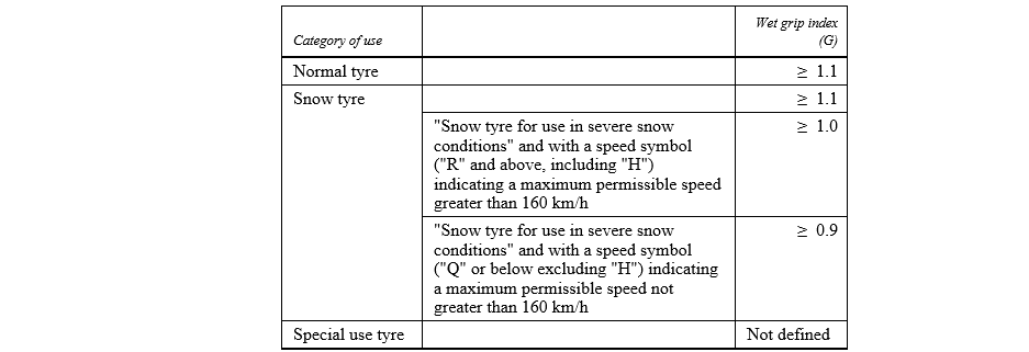
The minimum snow grip index value, as calculated in the procedure described in Annex 7 and compared with the respective Standard Reference Test Tyre (SRTT) shall be as follows: |
a3c0 |
| ... |
|
a5c0 |
|
|
Ice performance requirements for class C1 tyres classified as ice grip tyre In order to be classified as ice grip tyre, a snow tyre for use in severe snow conditions shall meet the minimum ice grip index value, as calculated in the procedure described in Annex 8 and compared with the respective Standard Reference Test Tyre (SRTT) shall be as follows:
|
a6c0 |
| 6.5. |
In order to be classified as a "traction tyre", a tyre is required to meet at least one of the conditionDEL of paragraph 6.5.1. below. |
a6c0 |
| 6.5.1. |
The tyre shall have a tread pattern with minimum two circumferential ribs, each containing a minimum of 30 block-like elements, separated by grooves and/or sipe elements the depth of which has to be minimum of one half of the tread depth. The use of an alternative option of a physical test will only apply at a later stage following a further amendment to the Regulation including a reference to DEL appropriate test methods and limit values. |
a6c0 |
| 6.6. | In order to be classified as a "special use tyre" a tyre shall have a block tread pattern in which the blocks are larger and more widely spaced than for normal tyres and have the following characteristics: | a0c0 |
| ... |
For class C1 tyres: a tread depth ≥ 11 mm and void to fill ratio ≥ 35 per cent |
a6c0 |
| ... |
For class C2 tyres: a tread depth ≥ 11 mm and void to fill ratio ≥ 35 per cent |
a6c0 |
| ... |
For class C3 tyres: a tread depth ≥ 16 mm and void to fill ratio ≥ 35 per cent |
a6c0 |
| 6.7. | In order to be classified as a "professional off-road tyre", a tyre shall have all of the following characteristics: | a0c0 |
| ... |
(a) For classes C1 and C2 tyres: |
a6c0 |
| ... | (i) A tread depth ≥ 11 mm; | a0c0 |
| ... | (ii) A void-to-fill ratio ≥ 35 per cent; | a0c0 |
| ... | (iii) A maximum speed rating of ≤ Q. | a0c0 |
| ... |
(b) For class C3 tyres: |
a6c0 |
| ... | (i) A tread depth ≥ 16 mm; | a0c0 |
| ... | (ii) A void-to-fill ratio ≥ 35 per cent; | a0c0 |
| ... | (iii) A maximum speed rating of Ͱa K. | a0c0 |
| 7. |
|
a1c0 |
| 7.1. | Every modification of the type of tyre, which may influence the performance characteristics approved in accordance with this Regulation, shall be notified to the Type Approval Authority which approved the type of tyre. That Authority may either: | a0c0 |
| 7.1.1. | Consider that the modifications are unlikely to have any appreciable adverse effect on the performance characteristics approved and that the tyre will comply with the requirements of this Regulation; or | a0c0 |
| 7.1.2. | Require further samples to be submitted for test or further test reports from the designated Technical Service. | a0c0 |
|
7. |
Confirmation or refusal of approval, specifying the modifications, shall be communicated by the procedure given in paragraph 5.3. of this Regulation to the Parties to the Agreement which apply this Regulation. |
a5c0 |
|
7. |
The Type Approval Authority granting the extension of approval shall assign a series number for such an extension which shall be shown on the communication form. |
a5c0 |
| 8. |
|
a0c0 |
| ... |
The conformity of production procedures shall comply with those set out in the 1958 Agreement, Schedule 1 (E/ECE/324-E/ECE/TRANS/505/Rev.3) with the following requirements: |
a6c0 |
| 8.1. | Any tyre approved under this Regulation shall be so manufactured as to conform to the performance characteristics of the type of tyre approved and satisfy the requirements of paragraph 6. above; | a0c0 |
| 8.2. |
DEL The authority which has granted type approval may at any time verify the conformity control methods applied by the manufacturer. In general, the conformity control methods should take into consideration the production volumes of the type of tyre at each manufacturing facility. The normal frequency of these verifications shall be at least once every two years. |
a6c0 |
|
|
Verification tests shall be carried out on random samples of tyres bearing the approval mark required by this Regulation taken from the series production. Where the test procedure involves testing a number of tyres at the same time, for example a set of four tyres for the purpose of measuring wet adhesion in accordance with the standard vehicle procedure given in Annex 5 to this Regulation, then the set shall be considered as being one unit for the purposes of calculating the number of tyres to be tested. The Type Approval Authority shall satisfy itself that all tyres falling within an approved type comply with the approval requirement. |
a6c0 |
|
8. |
In the case of verification tests with regard to approvals in accordance with paragraph 6.2. of this Regulation, these shall be carried out using the same testing method (see Annex 5 to this Regulation) as that adopted for original approval. |
a6c0 |
|
|
In the case of verification tests with regard to approvals in accordance with paragraph 6.4. of this Regulation, these shall be carried out using the same testing method (see Annex 7 to this Regulation) as that adopted for original approval. |
a6c0 |
|
8. |
Production shall be deemed to conform to the requirements of this Regulation if the levels measured comply with the limits prescribed in paragraph 6.1. of this Regulation, with an additional allowance of +1 dB(A) for possible mass production variations. |
a6c0 |
|
8. |
Production shall be deemed to conform to the requirements of this Regulation if the levels measured comply with the limits prescribed in paragraph 6.3. of this Regulation, with an additional allowance of +0.3 N/kN for possible mass production variations. |
a6c0 |
| 9. |
|
a0c0 |
| 9.1. |
The approval granted in respect of a type of tyre pursuant to this Regulation may be withdrawn if the requirements laid down in paragraph 8. above are not complied with, or if any tyre of the type of tyre exceeds the limits given in paragraphs 8. |
a5c0 |
| 9.2. | If a Party to the Agreement, which applies this Regulation, withdraws an approval, it has previously granted, it shall forthwith notify the other Contracting Parties applying this Regulation by means of a copy of the approval form conforming to the model in Annex 1 to this Regulation. | a0c0 |
| 10. |
|
a0c0 |
| ... |
If the holder of an approval completely ceases to manufacture a type of |
a1c0 |
| 11. |
|
a0c0 |
|
|
The |
a1c0 |
|
|
|
a1c0 |
|
|
|
a1c0 |
| 12. |
|
a0c0 |
| 12.1. |
As from the date of entry into force of the 02 series of amendments to this Regulation, Contracting Parties applying this Regulation shall not refuse to grant approval under this Regulation for a type of tyre if the tyre complies with the requirements of the 02 series of amendments, including the stage 1 or stage 2 rolling sound requirements set out in paragraphs 6.1.1. to 6.1.3. of this Regulation, the requirements for wet adhesion set out in paragraph 6.2.1. of this Regulation, and the stage 1 or stage 2 rolling resistance requirements set out in paragraph 6.3.1. or 6.3.2. of this Regulation. |
a6c0 |
| 12.2. |
As from 1 November 2012, Contracting Parties applying this Regulation shall refuse to grant approval if the type of tyre to be approved does not meet the requirements of this Regulation as amended by the 02 series of amendments, and shall, in addition, refuse to grant approval if the stage 2 rolling sound requirements set out in paragraphs 6.1.1. to 6.1.3. of this Regulation, the requirements for wet adhesion set out in paragraph 6.2.1. of this Regulation, and the stage 1 rolling resistance requirements set out in paragraph 6.3.1. of this Regulation are not complied with. |
a6c0 |
| 12.3. |
As from 1 November 2014, Contracting Parties applying this Regulation may refuse to allow the sale or entry into service of a tyre which does not meet the requirements of this Regulation as amended by the 02 series, and which does not meet the requirements of this Regulation as amended by the 02 series of amendments including the wet adhesion requirements set out in paragraph 6.2.1. of this Regulation. |
a6c0 |
| 12.4. |
As from 1 November 2016, Contracting Parties applying this Regulation shall refuse to grant approvals if the type of tyre to be approved does not meet the requirements of this Regulation as amended by the 02 series of amendments including the stage 2 rolling resistance requirements set out in paragraph 6.3.2. of this Regulation and the wet adhesion requirements set out in paragraphs 6.2.2. and 6.2.3. of this Regulation. |
a6c0 |
| 12.5. | As from 1 November 2016, any Contracting Party applying this Regulation may refuse to allow the sale or entry into service of a tyre which does not meet the requirements of this Regulation as amended by the 02 series, and which does not meet the stage 2 rolling sound requirements set out in paragraphs 6.1.1. to 6.1.3. of this Regulation. | a0c0 |
| 12.6. | As from the dates given below, any Contracting Party applying this Regulation may refuse to allow the sale or entry into service of a tyre which does not meet the requirements of this Regulation as amended by the 02 series, and which does not meet the stage 1 rolling resistance requirements set out in paragraph 6.3.1. of this Regulation: | a0c0 |
| ... |

|
a0c0 |
| 12.7. |
As from the dates given below, any Contracting Party applying this Regulation may refuse to allow the sale or entry into service of a tyre which does not meet the requirements of this Regulation as amended by the 02 series, and which does not meet the stage 2 rolling resistance requirements set out in paragraph 6.3.2. of this Regulation and the wet adhesion requirements set out in paragraphs 6.2.2. and 6.2.3. of this Regulation: |
a6c0 |
| ... |

|
a0c0 |
| 12.8. | Until 13 February 2019 (60 months after the entry into force of Supplement 4 to the 02 series of amendments to this Regulation) Contracting Parties applying this Regulation may continue to grant type approvals according to the 02 series of amendments to this Regulation, based on the provisions of Annex 4 to this Regulation. | a0c0 |
|
|
Until 3 months after the date of entry into force of Supplement 11 to the 02 series of amendments to this Regulation, Contracting Parties applying this Regulation can continue to grant type approvals according to the 02 series of amendments to this Regulation, without taking into account the provisions of Supplement 11. |
a3c0 |
|
|
|
a5c0 |
|
|
|
a5c0 |
| ... |
|
a5c0 |
| 12.12. |
Until 1 September 2024, Contracting Parties applying this Regulation may continue to grant type approvals according to the 02 series of amendments to this Regulation, based on the test procedures for measuring wet adhesion described in Annex 5 of this Regulation, without taking into account the provisions of Supplement 13. |
a6c0 |
|
|
Until 3 months after the date of entry into force of Supplement 14 to the 02 series of amendments to this Regulation, Contracting Parties applying this Regulation can continue to grant type approvals according to the 02 series of amendments to this Regulation, without taking into account the provisions of Supplement 14. |
a6c0 |
| A1 |
|
a0c0 |
| A1 |
|
a0c0 |
| A1 | (maximum format: A4 (210 x 297 mm)) | a0c0 |
| A1 |

|
a0c0 |
| A1 | of a type of tyre with regard to "rolling sound emission level" and/or "adhesion performance on wet surfaces" and/or "rolling resistance" pursuant to Regulation No. 117 | a0c0 |
|
A1 |
|
a0c0 |
|
A1 |
|
a0c0 |
| A1 | a0c0 | |
| A1 |
Approval No. |
a2c0 |
| A1 1. |
Manufacturer's name and address [DEL]: |
a1c0 |
| A1 2. | If applicable, name and address of manufacturer's representative: | a0c0 |
| A1 3. |
"Tyre class" [DEL] of the type of tyre: |
a0c0 |
|
A1 |
Category of use" of the type of tyre: |
a3c0 |
|
A1 |
Snow tyre for use in severe snow conditions (Yes/No)[2] |
a3c0 |
|
A1 |
Ice grip tyre (Yes/No)[2] |
a6c0 |
|
A1 |
Traction tyre (Yes/No)[2] |
a3c0 |
|
A1 |
|
a2c0 |
|
A1 |
|
a2c0 |
|
A1 |
Tyre structure: |
a3c0 |
| A1 6. |
Type of tyre designation: |
a6c0 |
|
A1 |
Brand name(s)/trademark(s) of the type of tyre: |
a3c0 |
| A1 6.2. |
Trade description(s)/ commercial name(s) of the type of tyre: |
a6c0 |
|
A1 |
Technical service and, where applicable, test laboratory approved for purposes of approval or of verification of conformity tests: |
a3c0 |
|
A1 |
Performance(s) approved: sound level at (stage 1/stage 2),[2] wet adhesion level, rolling resistance level (stage 1/stage 2)[2] |
a3c0 |
|
A1 |
Sound level of the representative tyre size, see paragraph 2.7. of this Regulation, as per item 7. of the test report in Appendix 1 to Annex 3: ................ dB(A) at reference speed of 70/80 km/h [2] |
a3c0 |
| A1 8.2. |
Wet adhesion level of the representative tyre size, see paragraph 2.7. of this Regulation, as per DEL the test report examples shown in the appendix to Annex 5: ……………………… (G) using the vehicle or trailer method [2] |
a6c0 |
|
A1 |
Rolling resistance level of the representative tyre size, see paragraph 2.7. of this Regulation, as per item 7. of the test report in Appendix 1 to Annex 6 |
a3c0 |
| A1 8.4. |
Snow performance level of the representative tyre size, see paragraph 2.7. of DEL Regulation No. 117, as per item 7. of the test report in the appendix [5] to Annex 7:………………. (snow grip index) using the brake on snow method [2], spin traction method [2] or acceleration method [2]. |
a6c0 |
|
A1 |
Ice performance level of the representative tyre size, see paragraph 2.7. of Regulation No. 117, as per item 7. of the test report in the appendix 2 to Annex 8:…………………….…(ice grip index) using the brake on ice method. [2] |
a6c0 |
|
A1 |
Number of report issued by the Technical Service: |
a3c0 |
|
A1 |
Date of report issued by that Service: |
a3c0 |
|
A1 |
Reason(s) of extension (if applicable): |
a3c0 |
|
A1 |
Any remarks: |
a3c0 |
|
A1 |
Place: |
a3c0 |
|
A1 |
Date: |
a3c0 |
|
A1 |
Signature: |
a3c0 |
|
A1 |
Annexed to this communication are: |
a3c0 |
| A1 16.1. |
A list of documents in the approval file deposited at the Type Approval Authorities having delivered the approval and which can be obtained upon request. |
a5c0 |
| A1 16.2. |
A list of tyre size designations: Specify for each brand name/trademark and/or each trade description/commercial name the list of tyre size designations and service descriptions, adding in case of class C1 tyres whether "reinforced" (or "extra load") or not. |
a6c0 |
|
A1 |
|
a6c0 |
| A1 |
|
a6c0 |
|
A1 |
|
a5c0 |
| A2 |
|
a0c0 |
| A2 |
|
a6c0 |
| A2 | Arrangements of approval marks | a0c0 |
| A2 | (See paragraph 5.4. of this Regulation) | a0c0 |
| A2 | Approval according to Regulation No. 117 | a0c0 |
| A2 |

|
a0c0 |
| A2 |
The above approval mark, affixed to a tyre shows that a tyre concerned has been approved in the Netherlands (E 4) pursuant to Regulation No. 117 (marked by "S2") DEL, under approval number 0212345. This indicates that the approval is for rolling sound at stage 2 (S2). The first two digits of the approval number (02) indicate that the approval was granted in accordance with this Regulation which included 02 series of amendments DEL. |
a6c0 |
| A2 |

|
a0c0 |
| A2 |
The above approval mark shows that the tyre concerned has been approved in the Netherlands (E 4) pursuant to Regulation No. 117 (marked by "S1WR1") under approval number 0212345. This indicates that the approval is for rolling sound at stage 1 (S1), wet adhesion (W) and rolling resistance at stage 1 (R1). The first two digits of the approval number ("02") indicate that the approval was granted in accordance with this Regulation which included the 02 series of amendments. |
a6c0 |
| A2 |
|
a0c0 |
| A2 |
|
a6c0 |
|
A2 |
|
a0c0 |
| A2 |

|
a0c0 |
| A2 |
The above approval mark shows that the tyre concerned has been approved in the Netherlands (E 4) pursuant to UN Regulation No. 117 (marked by "S2" DEL), under approval number 0212345 and UN Regulation No. 30, under approval number 0236378. This indicates that the approval is for rolling sound at stage 2 (S2). The first two digits of the approval number ("02") in conjunction with "S2" indicate that the approval was granted in accordance with UN Regulation No. 117 which included the 02 series of amendments. The first two digits of the UN Regulation No. 30 approval number ("02") indicate that this Regulation included the 02 series of amendments. |
a6c0 |
| A2 |
|
a6c0 |
| A2 |
The above approval mark shows that the tyre concerned has been approved in the Netherlands (E 4) pursuant to UN Regulation No. 117 (marked by S2WR2 DEL ), under approval number 0212345 and Regulation No. 30 under approval number 0236378. The first two digits of the approval number (02) indicate that the approval was granted according to the 02 series of amendments and Regulation No. 30 included the 02 series of amendments. The above approval mark shows that the tyre concerned has been approved in the Netherlands (E 4) pursuant to UN Regulation No. 117 (marked by "S2WR2" DEL), under approval number 0212345 and UN Regulation No. 30, under approval number 0236378. This indicates that the approval is for rolling sound at stage 2 (S2), wet adhesion (W) and rolling resistance at stage 2 (R2). The first two digits of the approval number ("02") in conjunction with "S2WR2" indicate that the first approval was granted in accordance with UN Regulation No. 117 which included the 02 series of amendments. The first two digits of the UN Regulation No. 30 approval number ("02") indicate that this Regulation included the 02 series of amendments. |
a6c0 |
| A2 |

|
a0c0 |
| A2 | The above approval mark shows that the tyre concerned has been approved in the Netherlands (E 4) pursuant to Regulation No. 117 and the 02 series of amendments under approval number 0212345 (marked by S2), and Regulation No. 54. This indicates that the approval is for rolling sound stage 2 (S2). The first two digits of the Regulation No. 117 approval number (02) in conjunction with "S2" indicate that the first approval was granted in accordance with Regulation No. 117 which included the 02 series of amendments. The first two digits of Regulation No. 54 (00) indicate that this Regulation was in its original form. | a0c0 |
| A2 |

|
a0c0 |
| A2 | The above approval mark shows that the tyre concerned has been approved in the Netherlands (E 4) pursuant to Regulation No. 117 and the 02 series of amendments under approval number 0212345 (marked by S2 R2), and Regulation No. 54. This indicates that the approval is for rolling sound stage 2 (S2) and rolling resistance stage 2. The first two digits of the Regulation No. 117 approval number (02) in conjunction with "S2R2" indicate that the first approval was granted in accordance with Regulation No. 117 which included the 02 series of amendments. The first two digits of Regulation No. 54 (00) indicate that this Regulation was in its original form. | a0c0 |
| A2 |
|
a0c0 |
| A2 |
|
a5c0 |
|
A2 |
|
a0c0 |
| A2 |

|
a0c0 |
| A2 |
The above approval mark shows that the tyre concerned has been |
a5c0 |
| A2 |

|
a0c0 |
| A2 |
The above approval mark shows that the tyre concerned has been approved in the Netherlands (E 4) pursuant to Regulation No. 30 according to its 02 series of amendments (indicated by the first two digits of the approval number, "02") under approval number 0236378. It is also marked by "+ 02S1WR2" which indicates that the tyre was also approved pursuant to UN Regulation No. 117 (02 series of amendments) for S1 (rolling sound at stage 1), W (wet adhesion) and R2 (rolling resistance at stage 2) |
a6c0 |
| A2 |
|
a0c0 |
| A2 |
|
a6c0 |
|
A2 |
|
a6c0 |
| A2 |
|
a0c0 |
| A2 |
The above approval mark shows that the tyre concerned has been initially approved in the Netherlands (E 4) pursuant to UN Regulation No. 117 according to its 02 series of amendments (indicated by the first two digits of the approval number, "02") under approval number 0212345 (marked by "W"). This indicates that the approval is for W (wet adhesion). The "S2R2" preceded by "+" indicates that its approval has been extended under UN Regulation No. 117 to rolling sound at stage 2 and rolling resistance at stage 2 based on separate certificate(s). |
a6c0 |
| A2 |
|
a0c0 |
| A2 |
The above approval mark shows that the tyre concerned has been initially approved in the Netherlands (E 4) pursuant to UN Regulation No. 117 according to its 02 series of amendments (indicated by the first two digits of the approval number, "02") under approval number 0212345 (marked by "S1W"). This indicates that the approval is for S1 (rolling sound at stage 1) and W (wet adhesion). The "R1" preceded by "+" indicates that its approval has been extended under Regulation No. 117 to rolling resistance at stage 1 based on separate certificate(s). |
a6c0 |
| A2 |

|
a0c0 |
| A2 |
The above approval mark shows that the tyre concerned has been initially approved in the Netherlands (E 4) pursuant to UN Regulation No. 117 according to its 01 series of amendments (indicated by the first two digits of the approval number, "01") under approval number 0167890 (marked by "SW"). This indicates that the approval is for S (rolling sound at stage 1) and W (wet adhesion). The "02R1" preceded by "+" indicates that its approval has been extended under UN Regulation No. 117 according to its 02 series of amendments to rolling resistance at stage 1 based on separate certificate(s). |
a6c0 |
| A3 |
|
a0c0 |
| A3 |
|
a0c0 |
| A3 | Introduction | a0c0 |
| A3 | The presented method contains specifications on measuring instruments, measurement conditions and the measurement method, in order to obtain the sound level of a set of tyres mounted on a test vehicle rolling on a specified road surface. The maximum sound pressure level is to be recorded, when the test vehicle is coasting, by remote-field microphones; the final result for a reference speed is obtained from a linear regression analysis. Such test results cannot be related to tyre rolling sound measured during acceleration under power or deceleration under braking. | a0c0 |
| A3 1. | Measuring instruments | a0c0 |
| A3 1.1. | Acoustic measurements | a0c0 |
| A3 |
The sound level meter or the equivalent measuring system, including the windscreen recommended by the manufacturer shall meet or exceed the requirements of Type 1 instruments in accordance with [DEL] IEC 61672-1:2013. |
a3c0 |
| A3 | The measurements shall be made using the frequency weighting A, and the time weighting F. | a0c0 |
| A3 | When using a system that includes a periodic monitoring of the A-weighted sound level, a reading should be made at a time interval not greater than 30 ms. | a0c0 |
| A3 1.1.1. | Calibration | a0c0 |
| A3 |
At the beginning and at the end of every measurement session, the entire measurement system shall be checked by means of a sound calibrator that fulfils the requirements for sound calibrators of at least precision Class 1 according to IEC 60942:[DEL]2017. Without any further adjustment the difference between the readings of two consecutive checks shall be less than or equal to 0.5 dB(A). If this value is exceeded, the results of the measurements obtained after the previous satisfactory check shall be discarded. |
a3c0 |
| A3 1.1.2. | Compliance with requirements | a0c0 |
| A3 | The compliance of the sound calibration device with the requirements of IEC 60942:1988 shall be verified once a year and the compliance of the instrumentation system with the requirements of IEC 60651:1979/A1:1993, second edition shall be verified at least every two years, by a laboratory which is authorized to perform calibrations traceable to the appropriate standards. | a0c0 |
| A3 1.1.3. | Positioning of the microphone | a0c0 |
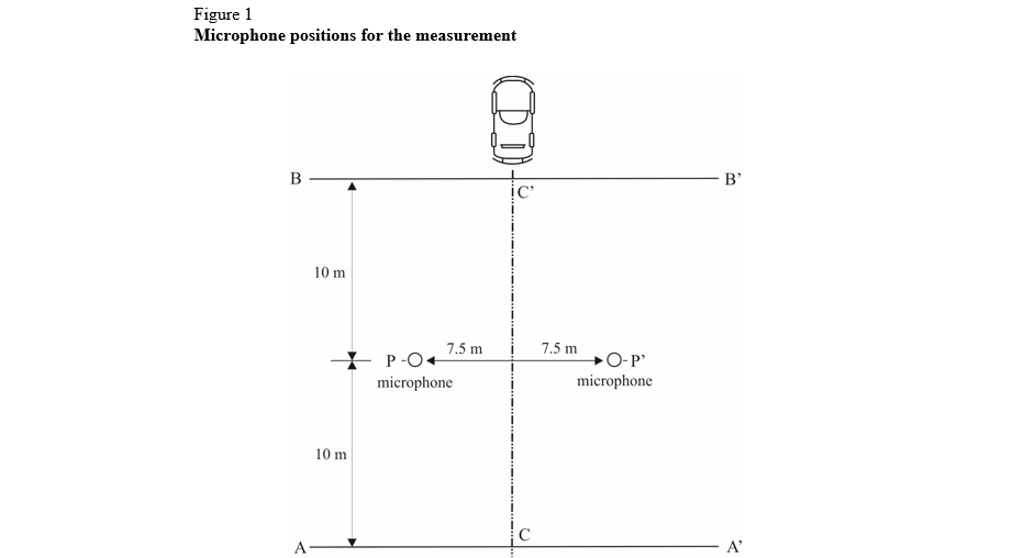
| A3 | The microphone (or microphones) shall be located at a distance of 7.5 ± 0.05 m from track reference line CC' (Figure 1) and 1.2 ± 0.02 m above the ground. Its axis of maximum sensitivity shall be horizontal and perpendicular to the path of the vehicle (line CC'). | a0c0 |
| A3 1.2. | Speed measurements | a0c0 |
| A3 | The vehicle speed shall be measured with instruments with accuracy of ± 1 km/h or better when the front end of the vehicle has reached line PP (Figure 1). | a0c0 |
| A3 1.3. | Temperature measurements | a0c0 |
| A3 | Measurements of air as well as test surface temperature are mandatory. | a0c0 |
| A3 | The temperature measuring devices shall be accurate within ± 1 °C. | a0c0 |
| A3 1.3.1. | Air temperature | a0c0 |
| A3 | The temperature sensor is to be positioned in an unobstructed location close to the microphone in such a way that it is exposed to the airflow and protected from direct solar radiation. The latter may be achieved by any shading screen or similar device. The sensor should be positioned at a height of 1.2 ± 0.1 m above the test surface level, to minimize the influence of the test surface thermal radiation at low airflows. | a0c0 |
| A3 1.3.2. | Test surface temperature | a0c0 |
| A3 | The temperature sensor is to be positioned in a location where the temperature measured is representative of the temperature in the wheel tracks, without interfering with the sound measurement. | a0c0 |
| A3 | If an instrument with a contact temperature sensor is used, heat-conductive paste shall be applied between the surface and the sensor to ensure adequate thermal contact. | a0c0 |
| A3 | If a radiation thermometer (pyrometer) is used, the height should be chosen to ensure that a measuring spot with a diameter of ≥ 0.1 m is covered. | a0c0 |
| A3 1.4. | Wind measurement | a0c0 |
| A3 | The device shall be capable of measuring the wind speed with a tolerance of ± 1 m/s. The wind shall be measured at microphone height. The wind direction with reference to the driving direction shall be recorded. | a0c0 |
| A3 2. | Conditions of measurement | a0c0 |
| A3 2.1. | Test site | a0c0 |
| A3 | The test site shall consist of a central section surrounded by a substantially flat test area. The measuring section shall be level; the test surface shall be dry and clean for all measurements. The test surface shall not be artificially cooled during or prior the testing. | a0c0 |
| A3 | The test track shall be such that the conditions of a free sound field between the sound source and the microphone are attained to within 1 dB(A). These conditions shall be deemed to be met if there is no large sound reflecting objects, such as fences, rocks, bridges or building within 50 m of the centre of the measuring section. The surface of the test track and the dimensions of the test site shall be in accordance with ISO 10844:2014. Until the end of the period indicated in paragraph 12.8. of this Regulation the specifications for the test site may be in accordance with Annex 4 to this Regulation. | a0c0 |
| A3 | A central part of at least 10 m radius shall be free of powdery snow, tall grass, loose soil, cinders or the like. There shall be no obstacle, which could affect the sound field within the vicinity of the microphone and no persons shall stand between the microphone and the sound source. The operator carrying out the measurements and any observers attending the measurements shall position themselves so as not to affect the readings of the measuring instruments. | a0c0 |
| A3 2.2. | Meteorological conditions | a0c0 |
| A3 | Measurements shall not be made under poor atmospheric conditions. It shall be ensured that the results are not affected by gusts of wind. Testing shall not be performed if the wind speed at the microphone height exceeds 5 m/s. | a0c0 |
| A3 | Measurements shall not be made if the air temperature is below 5 °C or above 40 °C or the test surface temperature is below 5 °C or above 50 °C. | a0c0 |
| A3 2.3. | Ambient noise | a0c0 |
| A3 2.3.1. | The background sound level (including any wind noise) shall be at least 10 dB(A) less than the measured tyre rolling sound emission. A suitable windscreen may be fitted to the microphone provided that account is taken of its effect on the sensitivity and directional characteristics of the microphone. | a0c0 |
| A3 2.3.2. | Any measurement affected by a sound peak which appears to be unrelated to the characteristics of the general sound level of tyres, shall be ignored. | a0c0 |
| A3 2.4. | Test vehicle requirements | a0c0 |
| A3 2.4.1. | General | a0c0 |
| A3 | The test vehicle shall be a motor vehicle and be fitted with four single tyres on just two axles. | a0c0 |
| A3 2.4.2. | Vehicle load | a0c0 |
| A3 | The vehicle shall be loaded such as to comply with the test tyre loads as specified in paragraph 2.5.2. below. | a0c0 |
| A3 2.4.3. | Wheelbase | a0c0 |
| A3 |
The wheelbase between the two axles fitted with the test tyres shall for class C1 be less than 3.50 m and for class C2 and class C3 tyres be less than 5 m. |
a6c0 |
| A3 2.4.4. | Measures to minimize vehicle influence on sound level measurements | a0c0 |
| A3 | To ensure that tyre rolling sound is not significantly affected by the test vehicle design the following requirements and recommendations are given. | a0c0 |
| A3 2.4.4.1. | Requirements: | a0c0 |
| A3 | (a) Spray suppression flaps or other extra device to suppress spray shall not be fitted; | a0c0 |
| A3 | (b) Addition or retention of elements in the immediate vicinity of the rims and tyres, which may screen the emitted sound, is not permitted; | a0c0 |
| A3 | (c) Wheel alignment (toe in, camber and caster) shall be in full accordance with the vehicle manufacturer's recommendations; | a0c0 |
| A3 | (d) Additional sound absorbing material may not be mounted in the wheel housings or under the underbody; | a0c0 |
| A3 | (e) Suspension shall be in such a condition that it does not result in an abnormal reduction in ground clearance when the vehicle is loaded in accordance with the testing requirement. If available, body level Regulation systems shall be adjusted to give a ground clearance during testing which is normal for unladen condition. | a0c0 |
| A3 2.4.4.2. | Recommendations to avoid parasitic noise: | a0c0 |
| A3 | (a) Removal or modification on the vehicle that may contribute to the background noise of the vehicle is recommended. Any removals or modifications shall be recorded in the test report; | a0c0 |
| A3 | (b) During testing it should be ascertained that brakes are not poorly released, causing brake noise; | a0c0 |
| A3 | (c) It should be ascertained that electric cooling fans are not operating; | a0c0 |
| A3 | (d) Windows and sliding roof of the vehicle shall be closed during testing. | a0c0 |
| A3 2.5. | Tyres | a0c0 |
| A3 2.5.1. | General | a0c0 |
| A3 |
Four identical tyres shall be fitted on the test vehicle. In the case of class C3 tyres with a load capacity index in excess of 121 and without any dual fitting indication, two of these tyres of the same type and range shall be fitted to the rear axle of the test vehicle; the front axle shall be fitted with tyres of size suitable for the axle load and planed down to the minimum depth in order to minimize the influence of tyre/road contact noise while maintaining a sufficient level of safety. In the case of class C2 tyres with a load capacity index lower or equal to 121, with a section width wider than 200 mm, an aspect ratio lower than 55, a rim diameter code lower than 15 and without any dual fitting indication, two of these tyres of the same type and range shall be fitted to the rear axle of the test vehicle; the front axle shall be fitted with tyres of a size suitable for the axle load and planed down to the minimum depth in order to minimize the influence of tyre/road contact noise while maintaining a sufficient level of safety. Tyres with special fitting requirements shall be tested in accordance with these requirements (e.g. rotation direction). The tyres shall have full tread depth before being run-in. Tyres are to be tested on rims permitted by the tyre manufacturer." |
a6c0 |
| A3 | Tyres are to be tested on rims permitted by the tyre manufacturer. | a0c0 |
| A3 2.5.2. | Tyre loads | a0c0 |
| A3 | The test load Qt for each tyre on the test vehicle shall be 50 to 90 per cent of the reference load Qr, but the average test load Qt,avr of all tyres shall be 75 ± 5 per cent of the reference load Qr. | a0c0 |
| A3 | For all tyres the reference load Qr corresponds to the maximum mass associated with the load capacity index of the tyre. In the case where the load capacity index is constituted by two numbers divided by slash (/), reference shall be made to the first number. | a0c0 |
| A3 2.5.3. | Tyre inflation pressure | a0c0 |
| A3 | Each tyre fitted on the test vehicle shall have a test pressure Pt not higher than the reference pressure Pr and within the interval: | a0c0 |
| A3 |

|
a0c0 |
| A3 |
For Class C2 and Class C3 the reference pressure Pr is the For class C2 and class C3 the reference pressure Pr is the inflation pressure corresponding to the DEL indication of the inflation pressure marked on the sidewall as required by paragraph 4.1. of this Regulation. |
a6c0 |
| A3 |
For class C1 the reference pressure is Pr = 250 kPa for "standard" tyres and 290 kPa for "reinforced" or "extra load" tyres; the minimum test pressure shall be Pt = 150 kPa. |
a6c0 |
| A3 2.5.4. | Preparations prior to testing | a0c0 |
| A3 | The tyres shall be "run-in" prior to testing to remove compound nodules or other tyre pattern characteristics resulting from the moulding process. This will normally require the equivalent of about 100 km of normal use on the road. | a0c0 |
| A3 | The tyres fitted to the test vehicle shall rotate in the same direction as when they were run-in. | a0c0 |
| A3 | Prior to testing tyres shall be warmed up by running under test conditions. | a0c0 |
| A3 3. | Method of testing | a0c0 |
| A3 3.1. | General conditions | a0c0 |
| A3 | For all measurements the vehicle shall be driven in a straight line over the measuring section (AA' to BB') in such a way that the median longitudinal plane of the vehicle is as close as possible to the line CC'. | a0c0 |
| A3 | When the front end of the test vehicle has reached the line AA' the vehicle driver shall have put the gear selector on neutral position and switched off the engine. If abnormal noise (e.g. ventilator, self-ignition) is emitted by the test vehicle during the measurement, the test shall be disregarded. | a0c0 |
| A3 3.2. | Nature and number of measurements | a0c0 |
| A3 | The maximum sound level expressed in A-weighted decibels (dB(A)) shall be measured to the first decimal place as the vehicle is coasting between lines AA' and BB' (Figure 1 - front end of the vehicle on line AA', rear end of the vehicle on line BB'). This value will constitute the result of the measurement. | a0c0 |
| A3 | At least four measurements shall be made on each side of the test vehicle at test speeds lower than the reference speed specified in paragraph 4.1. below and at least four measurements at test speeds higher than the reference speed. The speeds shall be approximately equally spaced over the speed range specified in paragraph 3.3. below. | a0c0 |
| A3 3.3. | Test speed range | a0c0 |
| A3 | The test vehicle speeds shall be within the range: | a0c0 |
| A3 |
(a) From 70 to 90 km/h for class C1 and class C2 tyres; |
a6c0 |
| A3 |
(b) From 60 to 80 km/h for class C3 tyres. |
a6c0 |
| A3 4. | Interpretation of results | a0c0 |
| A3 | The measurement shall be invalid if an abnormal discrepancy between the values is recorded (see paragraph 2.3.2. of this annex). | a0c0 |
| A3 4.1. | Determination of test result | a0c0 |
| A3 | Reference speed Vref used to determine the final result will be: | a0c0 |
| A3 |
(a) 80 km/h for class C1 and class C2 tyres; |
a6c0 |
| A3 |
(b) 70 km/h for class C3 tyres. |
a6c0 |
|
A3 4. |
Temperature correction |
a3c0 |
| A3 |
For Class C1 and Class C2 tyres, [DEL] the rolling sound levels Li(&thetasymi) obtained at the test surface temperature &thetasymi (where i denotes the number of the single measurement) shall be normalized to a test surface reference temperature &thetasymref by applying a temperature correction, according to the following formula: |
a3c0 |
| A3 |
|
a3c0 |
| A3 |
Notwithstanding the above procedure, the temperature correction may be made only on the final reported tyre rolling sound level LR, utilizing the arithmetic mean value of the measured temperatures, if the measured test surface temperature does not change more than 5 °C within all measurements necessary for the determination of the sound level of one set of tyres.[DEL] In this case the regression analysis below shall be based on the uncorrected rolling sound levels Li(&thetasymi). There will be no temperature correction for Class C3 tyres. |
a3c0 |
|
A3 4. |
Regression analysis of rolling sound measurements |
a3c0 |
| A3 |
The tyre-road rolling sound level LR(&thetasymref) in dB(A) is determined by a regression analysis according to: |
a3c0 |
| A3 |
|
a3c0 |
| A3 | There will be no temperature correction for Class C3 tyres. | a0c0 |
| A3 4.4. |
In order to take account of any measuring instrument inaccuracies, the temperature corrected tyre rolling sound level LR(&thetasymref) in dB(A) shall be reduced by 1 dB(A) and then rounded down to the nearest lower whole value to obtain the final result. |
a3c0 |
| A3 4.5. |
[DEL] |
a3c0 |
| A3 |
|
a0c0 |
| A3 |
|
a0c0 |
| A3 |
|
a0c0 |
| A3 | Part 1 - Report | a0c0 |
| A3 1. | Type Approval Authority or Technical Service: | a0c0 |
| A3 2. |
Name and address of manufacturer [DEL]: |
a3c0 |
| A3 3. | Test report No.: | a0c0 |
| A3 4. |
[DEL] Brand Name and [DEL] Trade description: |
a3c0 |
| A3 5. | Tyre Class (C1, C2 or C3): | a0c0 |
| A3 6. | Category of use: | a0c0 |
| A3 6.1. |
Snow tyre use in severe snow conditions (Yes/No)1 |
a6c0 |
|
A3 |
Traction tyre (Yes/No)1 |
a3c0 |
| A3 7. |
Sound level according to paragraphs 4.4. [DEL] of Annex 3: ...........dB(A) |
a3c0 |
| A3 | at reference speed of 70/80 km/h[1] | a0c0 |
|
A3 |
|
a0c0 |
| A3 8. | Comments (if any): | a0c0 |
| A3 9. | Date: | a0c0 |
| A3 10. | Signature: | a0c0 |
| A3 | Part 2 - Test data | a0c0 |
| A3 1. | Date of test: | a0c0 |
| A3 2. | Test vehicle (Make, model, year, modifications, etc.): | a0c0 |
| A3 2.1. | Test vehicle wheelbase: mm | a0c0 |
| A3 3. | Location of test track: | a0c0 |
| A3 3.1. | Date of track certification to ISO 10844:2014: | a0c0 |
| A3 3.2. | Issued by: | a0c0 |
| A3 3.3. | Method of certification: | a0c0 |
| A3 4. | Tyre test details: | a0c0 |
| A3 4.1. | Tyre size designation: | a0c0 |
| A3 4.2. | Tyre service description: | a0c0 |
| A3 4.3. |
Reference (test) inflation pressure2: kPa |
a3c0 |
|
A3 |
for classes C2 and C3 tyres, corresponding to the indication of the inflation pressure marked on the sidewall as required by paragraph 4.1. of this Regulation |
a6c0 |
| A3 4.4. | Test data: | a0c0 |
| A3 |

|
a0c0 |
| A3 4.5. | Test rim width code: | a0c0 |
| A3 4.6. | Temperature measurement sensor type: | a0c0 |
| A3 5. | Valid test results: | a0c0 |
| A3 |
|
a3c0 |
| A3 5.1. | Regression line slope: | a0c0 |
| A3 5.2. |
Sound level [DEL] according to paragraph 4.3. of Annex 3: dB(A) |
a3c0 |
| A4 |
Annex 4 |
a0c0 |
| A4 |
|
a0c0 |
|
A4 |
|
a0c0 |
| A4 1. | Introduction | a0c0 |
| A4 | This annex describes the specifications relating to the physical characteristics and the laying of the test track. These specifications based on a special standard[2] describe the required physical characteristics as well as the test methods for these characteristics. | a0c0 |
|
A4 |
|
a0c0 |
| A4 2. | Required characteristics of the surface | a0c0 |
| A4 | A surface is considered to conform to this standard provided that the texture and voids content or sound absorption coefficient have been measured and found to fulfil all the requirements of paragraphs 2.1. to 2.4. below and provided that the design requirements (paragraph 3.2. below) have been met. | a0c0 |
| A4 2.1. | Residual voids content | a0c0 |
| A4 | The residual Voids Content (VC) of the test track paving mixture shall not exceed 8 per cent. For the measurement procedure, see paragraph 4.1. of this annex. | a0c0 |
| A4 2.2. | Sound absorption coefficient | a0c0 |
| A4 | If the surface fails to comply with the residual voids content requirement, the surface is acceptable only if its sound absorption coefficient is α ≤ 0.10. For the measurement procedure, see paragraph 4.2. below. The requirements of this paragraph 2.1. above are met also if only sound absorption has been measured and found to be α ≤ 0.10. | a0c0 |
| A4 | Note: The most relevant characteristic is the sound absorption, although the residual voids content is more familiar among road constructors. However, sound absorption needs to be measured only if the surface fails to comply with the voids requirement. This is motivated because the latter is connected with relatively large uncertainties in terms of both measurements and relevance and some surfaces therefore erroneously may be rejected when based only on the voids measurement. | a0c0 |
| A4 2.3. | Texture depth | a0c0 |
| A4 | The Texture Depth (TD) measured according to the volumetric method (see paragraph 4.3. below) shall be: | a0c0 |
| A4 | TD ≥ 0.4 mm | a0c0 |
| A4 2.4. | Homogeneity of the surface | a0c0 |
| A4 | Every practical effort shall be taken to ensure that the surface is made to be as homogeneous as possible within the test area. This includes the texture and voids content, but it should also be observed that if the rolling process results in more effective rolling at some places than others, the texture may be different and unevenness causing bumps may also occur. | a0c0 |
| A4 2.5. | Period of testing | a0c0 |
| A4 | In order to check whether the surface continues to conform to the texture and voids content or sound absorption requirements stipulated in this standard, periodic testing of the surface shall be done at the following intervals: | a0c0 |
| A4 | (a) For residual VC or sound absorption (α): | a0c0 |
| A4 | When the surface is new: | a0c0 |
| A4 | If the surface meets the requirements when new, no further periodical testing is required. If it does not meet the requirement when it is new, it may do so later because surfaces tend to become clogged and compacted with time; | a0c0 |
| A4 | (b) For TD: | a0c0 |
| A4 | When the surface is new: | a0c0 |
| A4 | When the noise testing starts (Note: Not before four weeks after laying); | a0c0 |
| A4 | Then every twelve months. | a0c0 |
| A4 3. | Test surface design | a0c0 |
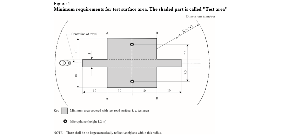
| A4 3.1. | Area | a0c0 |
| A4 | When designing the test track layout it is important to ensure that, as a minimum requirement, the area traversed by the vehicles running through the test strip is covered with the specified test material with suitable margins for safe and practical driving. This will require that the width of the track is at least 3 m and the length of the track extends beyond lines AA and BB by at least 10 m at either end. Figure 1 shows a plan of a suitable test site and indicates the minimum area which shall be machine laid and machine compacted with the specified test surface material. According to Annex 3, paragraph 3.2., measurements have to be made on each side of the vehicle. This can be made either by measuring with two microphone locations (one on each side of the track) and driving in one direction, or measuring with a microphone only on one side of the track but driving the vehicle in two directions. If the latter method is used, then there are no surface requirements on that side of the track where there is no microphone. | a0c0 |
| A4 |
|
a0c0 |
| A4 3.2. | Design and preparation of the surface | a0c0 |
| A4 3.2.1. | Basic design requirements | a0c0 |
| A4 | The test surface shall meet four design requirements: | a0c0 |
| A4 3.2.1.1. | It shall be a dense asphaltic concrete. | a0c0 |
| A4 3.2.1.2. | The maximum chipping size shall be 8 mm (tolerances allow from 6.3 mm to 10 mm). | a0c0 |
| A4 3.2.1.3. | The thickness of the wearing course shall be ≥ 30 mm. | a0c0 |
| A4 3.2.1.4. | The binder shall be a straight penetration grade bitumen without modification. | a0c0 |
| A4 3.2.2. | Design guidelines | a0c0 |
| A4 | As a guide to the surface constructor, an aggregate grading curve which will give desired characteristics is shown in Figure 2. In addition, Table 1 gives some guidelines in order to obtain the desired texture and durability. The grading curve fits the following formula: | a0c0 |
| A4 |

|
a0c0 |
| A4 |
|
a0c0 |
| A4 | In addition to the above, the following recommendations are given: | a0c0 |
| A4 | (a) The sand fraction (0.063 mm < square mesh sieve size < 2 mm) shall include no more than 55 per cent natural sand and at least 45 per cent crushed sand; | a0c0 |
| A4 | (b) The base and sub-base shall ensure a good stability and evenness, according to best road construction practice; | a0c0 |
| A4 | (c) The chippings shall be crushed (100 per cent crushed faces) and of a material with a high resistance to crushing; | a0c0 |
| A4 | (d) The chippings used in the mix shall be washed; | a0c0 |
| A4 | (e) No extra chippings shall be added onto the surface; | a0c0 |
| A4 | (f) The binder hardness expressed as PEN value shall be 40 - 60, 60 - 80 or even 80 - 100 depending on the climatic conditions of the country. The rule is that as hard a binder as possible shall be used, provided this is consistent with common practice; | a0c0 |
| A4 | (g) The temperature of the mix before rolling shall be chosen so as to achieve by subsequent rolling the required voids content. In order to increase the probability of satisfying the specifications of paragraphs 2.1. to 2.4. above, the compactness shall be studied not only by an appropriate choice of mixing temperature, but also by an appropriate number of passings and by the choice of compacting vehicle. | a0c0 |
| A4 |
|
a0c0 |
| A4 4. | Test method | a0c0 |
| A4 4.1. | Measurement of the residual voids content | a0c0 |
| A4 | For the purpose of this measurement, cores have to be taken from the track in at least four different positions, which are equally distributed in the test area between lines AA and BB (see Figure 1). In order to avoid in homogeneity and unevenness in the wheel tracks, cores should not be taken in wheel tracks themselves, but close to them. Two cores (minimum) should be taken close to the wheel tracks and one core (minimum) should be taken approximately midway between the wheel tracks and each microphone location. | a0c0 |
| A4 | If there is a suspicion that the condition of homogeneity is not met (see paragraph 2.4. above), cores shall be taken from more locations within the test area. | a0c0 |
| A4 | The residual voids content has to be determined for each core, then the average value from all cores shall be calculated and compared with the requirement of paragraph 2.1. of this annex. In addition, no single core shall have a voids value, which is higher than 10 per cent. | a0c0 |
| A4 | The test surface constructor is reminded of the problem, which may arise when the test area is heated by pipes or electrical wires and cores shall be taken from this area. Such installations shall be carefully planned with respect to future core drilling locations. It is recommended to leave a few locations of size approximately 200 mm x 300 mm where there are no wires/pipes or where the latter are located deep enough in order not to be damaged by cores taken from the surface layer. | a0c0 |
| A4 4.2. | Sound absorption coefficient | a0c0 |
| A4 | The sound absorption coefficient (normal incidence) shall be measured by the impedance tube method using the procedure specified in ISO 10534-1:1996 or ISO 10534-2:1998. | a0c0 |
| A4 | Regarding test specimens, the same requirements shall be followed as regarding the residual voids content (see paragraph 4.1. above). The sound absorption shall be measured in the range between 400 Hz and 800 Hz and in the range between 800 Hz and 1,600 Hz (at least at the centre frequencies of third octave bands) and the maximum values shall be identified for both of these frequency ranges. Then these values, for all test scores, shall be averaged to constitute the final result. | a0c0 |
| A4 4.3. | Volumetric macro-texture measurement | a0c0 |
| A4 | For the purpose of this standard, texture depth measurements shall be made on at least 10 positions evenly spaced along the wheel tracks of the test strip and the average value taken to compare with the specified minimum texture depth. See Standard ISO 10844:2014 for description of the procedure. | a0c0 |
| A4 5. | Stability in time and maintenance | a0c0 |
| A4 5.1. | Age influence | a0c0 |
| A4 | In common with any other surfaces, it is expected that the tyre rolling sound level measured on the test surface may increase slightly during the first | a0c0 |
| A4 | 6-12 months after construction. | a0c0 |
| A4 | The surface will achieve its required characteristics not earlier than four weeks after construction. The influence of age on the noise from trucks is generally less than that from cars. | a0c0 |
| A4 | The stability over time is determined mainly by the polishing and compaction by vehicles driving on the surface. It shall be periodically checked as stated in paragraph 2.5. above. | a0c0 |
| A4 5.2. | Maintenance of the surface | a0c0 |
| A4 | Loose debris or dust, which could significantly reduce the effective texture depth shall be removed from the surface. In countries with winter climates, salt is sometimes used for de-icing. Salt may alter the surface temporarily or even permanently in such a way as to increase noise and is therefore not recommended. | a0c0 |
| A4 5.3. | Repaving the test area | a0c0 |
| A4 | If it is necessary to repave the test track, it is usually unnecessary to repave more than the test strip (of 3 m width in Figure 1) where vehicles are driving, provided the test area outside the strip met the requirement of residual voids content or sound absorption when it was measured. | a0c0 |
| A4 6. | Documentation of the test surface and of tests performed on it | a0c0 |
| A4 6.1. | Documentation of the test surface | a0c0 |
| A4 | The following data shall be given in a document describing the test surface: | a0c0 |
| A4 6.1.1. | The location of the test track; | a0c0 |
| A4 6.1.2. | Type of binder, binder hardness, type of aggregate, maximum theoretical density of the concrete (DR), thickness of the wearing course and grading curve determined from cores from the test track; | a0c0 |
| A4 6.1.3. | Method of compaction (e.g. type of roller, roller mass, number of passes); | a0c0 |
| A4 6.1.4. | Temperature of the mix, temperature of the ambient air and wind speed during laying of the surface; | a0c0 |
| A4 6.1.5. | Date when the surface was laid and contractor; | a0c0 |
| A4 6.1.6. | All or at least the latest test result, including: | a0c0 |
| A4 6.1.6.1. | The residual voids content of each core; | a0c0 |
| A4 6.1.6.2. | The locations in the test area from where the cores for voids measurements have been taken; | a0c0 |
| A4 6.1.6.3. | The sound absorption coefficient of each core (if measured). Specify the results both for each core and each frequency range as well as the overall average; | a0c0 |
| A4 6.1.6.4. | The locations in the test area from where the cores for absorption measurement have been taken; | a0c0 |
| A4 6.1.6.5. | Texture depth, including the number of tests and standard deviation; | a0c0 |
| A4 6.1.6.6. | The institution responsible for tests according to paragraphs 6.1.6.1. and 6.1.6.2. above and the type of equipment used; | a0c0 |
| A4 6.1.6.7. | Date of the test(s) and date when the cores were taken from the test track. | a0c0 |
| A4 6.2. | Documentation of vehicle noise tests conducted on the surface | a0c0 |
| A4 | In the document describing the vehicle noise test(s) it shall be stated whether all the requirements of this standard were fulfilled or not. Reference shall be given to a document according to paragraph 6.1. above describing the results which verify this. | a0c0 |
| A5 |
|
a0c0 |
| A5 |
|
a6c0 |
| A5 |
(A) - Class C1 tyres |
a6c0 |
| A5 1. | Reference standards | a0c0 |
| A5 | The following documents listed apply. | a0c0 |
|
A5 |
|
a5c0 |
|
A5 |
|
a5c0 |
|
A5 1. |
ASTM E 965-96 (Reapproved 2006), Standard Test Method for Measuring Pavement Macrotexture Depth Using a Volumetric Technique. |
a5c0 |
|
A5 |
|
a3c0 |
| A5 1.5. |
|
a3c0 |
| A5 2. | Definitions | a0c0 |
| A5 |
In addition to the definitions in paragraph 2. of the main body of this Regulation, for the purposes of testing wet adhesion of class C1 tyres: |
a6c0 |
|
A5 |
DEL |
a6c0 |
|
A5 |
|
a6c0 |
|
A5 |
|
a6c0 |
|
A5 |
DEL |
a6c0 |
|
A5 |
DEL |
a6c0 |
|
A5 2. |
"Reference tyre" or "Reference tyre set" means a tyre or a tyre set of Standard Reference Test Tyres SRTT16. |
a6c0 |
|
A5 |
|
a5c0 |
|
A5 2. |
"Braking force" means the longitudinal force, expressed in newtons, resulting from braking torque application. |
a6c0 |
|
A5 2. |
"Average Braking Force Coefficient" (BFC) means, for the vehicle method, the ratio of the average deceleration in a braking test to the acceleration due to gravity (rounded to 9.81 m∙s−2). |
a6c0 |
|
A5 |
"Dynamic braking force coefficient" (μ(t)) means, for the trailer (or tyre test vehicle) method, the ratio of the braking force to the vertical load acquired in real time. |
a6c0 |
|
A5 2. |
"Peak braking force coefficient" (μpeak) means, for the trailer (or tyre test vehicle) method, the maximum value of the dynamic braking force coefficient that occurs prior to lockup of the wheel as the braking torque is progressively increased. |
a6c0 |
|
A5 2. |
"Lockup of a wheel" means the condition of a wheel in which its rotational velocity about the wheel spin axis is zero and it is prevented from rotating in the presence of applied wheel torque. |
a6c0 |
|
A5 2. |
"Vertical load" means the normal force, expressed in newtons, exerted on the road resulting from the mass supported by the tyre. |
a6c0 |
|
A5 2. |
"Tyre test vehicle" means a dedicated special purpose vehicle which has instruments to measure the vertical and the longitudinal forces on one test tyre during braking. |
a6c0 |
|
A5 |
|
a3c0 |
|
A5 |
|
a3c0 |
|
A5 |
"Tyre set" means, for the trailer (or tyre test vehicle) method, one (1) tyre and, for the vehicle method, four (4) tyres. |
a6c0 |
|
A5 |
"Instrumented passenger car" means a commercialized passenger car equipped with an Antilock Braking System (ABS) and the measuring equipment listed in paragraph 4.1.2.2. of this Annex.. |
a6c0 |
| A5 3. | General test conditions | a0c0 |
| A5 3.1. | Track characteristics | a0c0 |
| A5 | The test track shall have the following characteristics: | a0c0 |
| A5 3.1.1. |
The surface shall have a dense asphalt surface with a uniform gradient of not more than 2 per cent |
a5c0 |
| A5 3.1.2. | The surface shall have a pavement of uniform age, composition, and wear. The test surface shall be free of loose material and foreign deposits. | a0c0 |
| A5 3.1.3. | The maximum chipping size shall be 10 mm (tolerances permitted from 8 mm to 13 mm). | a0c0 |
| A5 3.1.4. |
The |
a5c0 |
| A5 3.1.5. |
The wetted frictional properties of the surface shall be measured using the SRTT16 either with the method described in paragraph 3.2.1. of this Annex in case the vehicle method (according to paragraph 4.1. below) is used, or with the method described in paragraph 3.2.2. in this Annex in case the trailer (or tyre test vehicle) method is used. |
a6c0 |
| A5 3.2. | Methods to measure the wetted frictional properties of the surface | a0c0 |
| A5 3.2.1. |
|
a5c0 |
| A5 |
|
a5c0 |
| A5 |
|
a5c0 |
| A5 |
|
a5c0 |
| A5 |
|
a5c0 |
| A5 |
|
a5c0 |
| A5 |
|
a5c0 |
| A5 |
|
a5c0 |
| A5 |
|
a5c0 |
| A5 |
|
a5c0 |
| A5 3.2.2. |
|
a5c0 |
| A5 |
|
a5c0 |
| A5 |
|
a5c0 |
| A5 |
|
a5c0 |
| A5 |
|
a3c0 |
| A5 |
|
a5c0 |
| A5 |
|
a5c0 |
| A5 3.3. | Atmospheric conditions | a0c0 |
| A5 | The wind conditions shall not interfere with wetting of the surface (wind-shields are allowed). | a0c0 |
| A5 |
|
a5c0 |
| A5 |
|
a5c0 |
| A5 |
The ambient temperature |
a5c0 |
|
A5 |
Replacement of reference tyres |
a5c0 |
| A5 |
When irregular wear or damage results from tests, or when wear |
a5c0 |
| A5 4. |
Testing methods for measuring wet adhesion |
a6c0 |
| A5 | For the calculation of the wet grip index (G) of a candidate tyre, the wet grip braking performance of the candidate tyre is compared to the wet grip braking performance of the reference tyre on a vehicle travelling straight ahead on a wet, paved surface. It is measured with one of the following methods: | a0c0 |
| A5 | (a) Vehicle method consisting of testing a set of tyres mounted on an instrumented passenger car; | a0c0 |
| A5 | (b) Testing method using a trailer towed by a vehicle or a tyre test vehicle, equipped with the test tyre(s). | a0c0 |
| A5 4.1. | Testing method (a) using an instrumented passenger car | a0c0 |
| A5 4.1.1. | Principle | a0c0 |
| A5 |
The testing method covers a procedure for measuring the deceleration performance of class C1 tyres during braking, using an instrumented passenger car. |
a6c0 |
| A5 4.1.2. | Equipment | a0c0 |
| A5 4.1.2.1. | Vehicle | a0c0 |
| A5 |
Permitted modifications on the passenger car are as follows: |
a5c0 |
| A5 | (a) Those allowing the number of tyre sizes that can be mounted on the vehicle to be increased; | a0c0 |
| A5 | (b) Those permitting automatic activation of the braking device to be installed; | a0c0 |
| A5 |
(c) Any other modification |
a5c0 |
| A5 4.1.2.2. | Measuring equipment | a0c0 |
| A5 |
|
a5c0 |
| A5 |
To measure vehicle speed, a fifth wheel or non-contact |
a5c0 |
| A5 4.1.3. | Conditioning of the test track and wetting condition | a0c0 |
| A5 |
The test track surface shall be watered at least half an hour prior to testing in order to equalize the surface temperature and water temperature. External watering should be supplied continuously throughout testing. For the whole testing area, the water depth shall be |
a5c0 |
| A5 | The test track should then be conditioned by conducting at least ten test runs with tyres not involved in the test programme at 90 km/h. | a0c0 |
| A5 4.1.4. | Tyres and rims | a0c0 |
| A5 4.1.4.1. |
|
a5c0 |
| A5 | The test tyres shall be trimmed to remove all protuberances on the tread surface caused by mould air vents or flashes at mould junctions. | a0c0 |
| A5 |
Fit the test tyres on rims specified by a recognized tyre and rim standards organization as listed in Appendix 4 to Annex 6 to this Regulation. |
a5c0 |
| A5 4.1.4.2. | Tyre load | a0c0 |
| A5 |
The static load on each axle tyre shall lie between 60 per cent and 90 per cent of the tested tyre load capacity. Tyre loads on the same axle should not differ by more than 10 per cent. |
a5c0 |
| A5 4.1.4.3. | Tyre inflation pressure | a0c0 |
| A5 |
On the front axle
|
a5c0 |
| A5 4.1.5. | Procedure | a0c0 |
| A5 4.1.5.1. | Test run | a0c0 |
| A5 | The following test procedure applies for each test run. | a0c0 |
| A5 4.1.5.1.1. |
The passenger car is driven in a straight line up to |
a5c0 |
| A5 4.1.5.1.2. |
Once the passenger car has reached |
a5c0 |
| A5 4.1.5.1.3. | The brakes are activated either automatically or manually. | a0c0 |
| A5 4.1.5.1.3.1. | The automatic activation of the brakes is performed by means of a detection system made of two parts, one indexed to the test track and one on board the passenger car. | a0c0 |
| A5 4.1.5.1.3.2. |
The manual activation of the brakes depends on the type of transmission as follows. In both cases, |
a5c0 |
| A5 |
For manual transmission, |
a5c0 |
| A5 |
For automatic transmission, |
a5c0 |
| A5 |
|
a5c0 |
| A5 4.1.5.1.4. |
|
a5c0 |
| A5 |
If any of the specifications listed above (including speed tolerance, longitudinal and transverse tolerance for the braking starting point, and braking time) are not met when a test run is made, the |
a5c0 |
| A5 4.1.5.2. |
|
a5c0 |
| A5 |
|
a5c0 |
| A5 4.1.5.2.1. |
|
a5c0 |
| A5 4.1.5.2.2. |
|
a5c0 |
| A5 4.1.5.2.3. |
After |
a5c0 |
| A5 4.1.5.2.4. |
|
a5c0 |
| A5 | Examples: | a0c0 |
| A5 |
(a) The run order for a test cycle of three sets of candidate tyres (T1 to T3) |
a5c0 |
| A5 |
(b) The run order for a |
a5c0 |
| A5 4.1.6. | Processing of measurement results | a0c0 |
| A5 4.1.6.1. |
Calculation of the average |
a5c0 |
| A5 |
|
a5c0 |
| A5 | Where: | a0c0 |
| A5 |
|
a5c0 |
| A5 |
|
a5c0 |
| A5 |
|
a5c0 |
| A5 |
|
a5c0 |
| A5 4.1.6.2. | Validation of results | a0c0 |
| A5 |
The |
a5c0 |
| A5 |
|
a5c0 |
| A5 |
For the reference tyres
|
a5c0 |
| A5 |
For the candidate tyres (T): The |
a5c0 |
| A5 4.1.6.3. |
Calculation of adjusted average |
a5c0 |
| A5 |
The |
a5c0 |
| A5 |
|
a5c0 |
| A5 |
|
a5c0 |
|
A5 |
|
a5c0 |
| A5 |
|
a5c0 |
| A5 |
|
a5c0 |
|
A5 4.1.6. |
Calculation of the wet grip index of the candidate tyre |
a5c0 |
| A5 |
The wet grip index |
a5c0 |
| A5 |
|
a5c0 |
| A5 | Where: | a0c0 |
| A5 |
|
a5c0 |
| A5 |
|
a5c0 |
| A5 |
|
a5c0 |
| A5 |
|
a5c0 |
| A5 4.1.7. |
|
a5c0 |
|
A5 |
|
a5c0 |
| A5 |
|
a5c0 |
|
A5 |
|
a5c0 |
| A5 |
|
a5c0 |
| A5 |
|
a5c0 |
| A5 |
|
a5c0 |
| A5 |
|
a5c0 |
| A5 |
|
a5c0 |
| A5 |
|
a5c0 |
| A5 |
|
a5c0 |
| A5 |
|
a5c0 |
| A5 |
|
a5c0 |
| A5 |
|
a5c0 |
| A5 |
|
a5c0 |
| A5 |
|
a5c0 |
|
A5 |
|
a5c0 |
| A5 |
|
a5c0 |
| A5 4.2. | Testing method (b) using a trailer towed by a vehicle or a tyre test vehicle | a0c0 |
| A5 4.2.1. | Principle | a0c0 |
| A5 | The measurements are conducted on test tyres mounted on a trailer towed by a vehicle (hereafter referred to as tow vehicle) or on a tyre test vehicle. The brake in the test position is applied firmly until sufficient braking torque is generated to produce the maximum braking force that will occur prior to wheel lockup at a test speed of 65 km/h. | a0c0 |
| A5 4.2.2. | Equipment | a0c0 |
| A5 4.2.2.1. | Tow vehicle and trailer or tyre test vehicle | a0c0 |
| A5 |
The tow vehicle or the tyre test vehicle shall have the capability of maintaining the specified speed of |
a5c0 |
| A5 |
The trailer or the tyre test vehicle shall be equipped with one place where the tyre can be fitted for measurement purposes, here |
a5c0 |
| A5 | (a) Equipment to activate brakes in the test position; | a0c0 |
| A5 | (b) A water tank to store sufficient water to supply the road surface wetting system, unless external watering is used; | a0c0 |
| A5 | (c) Recording equipment to record signals from transducers installed at the test position and to monitor water application rate if the self-watering option is used. | a0c0 |
| A5 |
|
a5c0 |
| A5 | The maximum variation of toe-settings and camber angle for the test position shall be within ± 0.5° with maximum vertical load. Suspension arms and bushings shall have sufficient rigidity necessary to minimize free play and ensure compliance under application of maximum braking forces. The suspension system shall provide adequate load-carrying capacity and be of such a design as to isolate suspension resonance. | a0c0 |
| A5 | The test position shall be equipped with a typical or special automotive brake system which can apply sufficient braking torque to produce the maximum value of braking test wheel longitudinal force at the conditions specified. | a0c0 |
| A5 | The brake application system shall be able to control the time interval between initial brake application and peak longitudinal force as specified in paragraph 4.2.7.1. below. | a0c0 |
| A5 | The trailer or the tyre test vehicle shall be designed to accommodate the range of candidate tyre sizes to be tested. | a0c0 |
| A5 | The trailer or the tyre test vehicle shall have provisions for adjustment of vertical load as specified in paragraph 4.2.5.2. below | a0c0 |
| A5 4.2.2.2. | Measuring equipment | a0c0 |
| A5 | The test wheel position on the trailer or the tyre test vehicle shall be equipped with a rotational wheel velocity measuring system and with transducers to measure the braking force and vertical load at the test wheel. | a0c0 |
| A5 | General requirements for measurement system: The instrumentation system shall conform to the following overall requirements at ambient temperatures between 0 °C and 45 °C: | a0c0 |
| A5 | (a) Overall system accuracy, force: ± 1.5 per cent of the full scale of the vertical load or braking force; | a0c0 |
| A5 | (b) Overall system accuracy, speed: ± 1.5 per cent of speed or ± 1.0 km/h, whichever is greater. | a0c0 |
| A5 | Vehicle speed: To measure vehicle speed, a fifth wheel or non-contact precision speed-measuring system should be used. | a0c0 |
| A5 | Braking forces: The braking force-measuring transducers shall measure longitudinal force generated at the tyre-road interface as a result of brake application within a range from 0 per cent to at least 125 per cent of the applied vertical load. The transducer design and location shall minimize inertial effects and vibration-induced mechanical resonance. | a0c0 |
| A5 | Vertical load: The vertical load-measuring transducer shall measure the vertical load at the test position during brake application. The transducer shall have the same specifications as described previously. | a0c0 |
| A5 | Signal conditioning and recording system: All signal conditioning and recording equipment shall provide linear output with necessary gain and data reading resolution to meet the specified previous requirements. In addition, the following requirements apply: | a0c0 |
| A5 |
(a) The minimum frequency response shall be flat from 0 Hz to |
a5c0 |
| A5 | (b) The signal-to-noise ratio shall be at least 20/1; | a0c0 |
| A5 | (c) The gain shall be sufficient to permit full-scale display for full-scale input signal level; | a0c0 |
| A5 | (d) The input impedance shall be at least ten times larger than the output impedance of the signal source; | a0c0 |
| A5 | (e) The equipment shall be insensitive to vibrations, acceleration, and changes in ambient temperature. | a0c0 |
| A5 4.2.3. | Conditioning of the test track | a0c0 |
| A5 |
The test track should be conditioned by conducting at least ten test runs with tyres not involved in the test program at |
a5c0 |
| A5 4.2.4. | Wetting conditions | a0c0 |
| A5 |
|
a5c0 |
|
A5 |
|
a5c0 |
|
A5 |
|
a5c0 |
| A5 | The nozzle configuration and position shall ensure that the water jets are directed towards the test tyre and pointed towards the pavement at an angle of 20° to 30°. | a0c0 |
| A5 | The water shall strike the pavement 250 mm to 450 mm ahead of the centre of tyre contact. The nozzle shall be located 25 mm above the pavement or at the minimum height required to clear obstacles which the tester is expected to encounter, but in no case more than 100 mm above the pavement. | a0c0 |
| A5 |
The water layer shall be at least 25 mm wider than the test tyre tread and applied so the tyre is centrally located between the edges. Water delivery rate shall ensure a water depth of |
a5c0 |
| A5 4.2.5. | Tyres and rims | a0c0 |
| A5 4.2.5.1. |
Tyre preparation and |
a5c0 |
| A5 | The test tyres shall be trimmed to remove all protuberances on the tread surface caused by mould air vents or flashes at mould junctions. | a0c0 |
| A5 |
The test tyre shall be mounted on a |
a5c0 |
| A5 | A proper bead seat should be achieved by the use of a suitable lubricant. Excessive use of lubricant should be avoided to prevent slipping of the tyre on the wheel rim. | a0c0 |
| A5 |
|
a5c0 |
| A5 | The test tyres/rim assemblies shall be stored in a location for a minimum of two hours such that they all have the same ambient temperature prior to testing. They should be shielded from the sun to avoid excessive heating by solar radiation. | a0c0 |
| A5 |
|
a5c0 |
| A5 4.2.5.2. | Tyre load | a0c0 |
| A5 |
The test load on the test tyre is |
a5c0 |
| A5 4.2.5.3. | Tyre inflation pressure | a0c0 |
| A5 | The test tyre cold inflation pressure shall be 180 kPa for standard-load tyres. For extra-load tyres, the cold inflation pressure shall be 220 kPa. | a0c0 |
| A5 | The tyre pressure should be checked just prior to testing at ambient temperature and adjusted if required. | a0c0 |
| A5 4.2.6. | Preparation of the tow vehicle and trailer or the tyre test vehicle | a0c0 |
| A5 4.2.6.1. |
|
a5c0 |
| A5 |
For one-axle trailers, the hitch height and transverse position shall be adjusted |
a5c0 |
| A5 4.2.6.2. | Instrumentation and equipment | a0c0 |
| A5 | Install the fifth wheel, when used, in accordance with the manufacturer's specifications and locate it as near as possible to the mid-track position of the tow trailer or the tyre test vehicle. | a0c0 |
| A5 4.2.7. | Procedure | a0c0 |
| A5 4.2.7.1. | Test run | a0c0 |
| A5 | The following procedure applies for each test run: | a0c0 |
| A5 4.2.7.1.1. |
The tow vehicle or the tyre test vehicle is driven onto the test track in a straight line at the specified test speed |
a5c0 |
| A5 4.2.7.1.2. | The recording system is launched. | a0c0 |
| A5 4.2.7.1.3. |
|
a5c0 |
| A5 4.2.7.1.4. |
The |
a5c0 |
| A5 4.2.7.1.5. | The recording system is stopped. | a0c0 |
| A5 4.2.7.2. | Test cycle | a0c0 |
| A5 |
|
a5c0 |
| A5 4.2.7.2.1. |
|
a5c0 |
| A5 4.2.7.2.2. |
|
a5c0 |
| A5 4.2.7.2.3. |
After |
a5c0 |
| A5 4.2.7.2.4. |
|
a5c0 |
| A5 Examples: | a0c0 | |
| A5 |
(a) The run order for a test cycle |
a5c0 |
| A5 |
R |
a5c0 |
| A5 |
(b) The run order for a |
a5c0 |
| A5 |
R |
a5c0 |
| A5 4.2.8. | Processing of measurement results | a0c0 |
| A5 4.2.8.1. | Calculation of the peak braking force coefficient | a0c0 |
| A5 |
|
a5c0 |
| A5 |
|
a5c0 |
| A5 | Where: | a0c0 |
| A5 | µ(t) is the dynamic tyre braking force coefficient in real time; | a0c0 |
| A5 |
f |
a5c0 |
| A5 |
f |
a5c0 |
| A5 4.2.8.2. | Validation of results | a0c0 |
| A5 |
The µpeak coefficient of variation CVµ is calculated as follows: |
a3c0 |
| A5 |
|
a3c0 |
| A5 |
For the reference tyre (R): (a) The coefficients of variation CVμ of the initial and the final braking tests of the reference tyre within one test cycle shall be less than or equal to 4 per cent;
|
a6c0 |
| A5 |
For the candidate tyre(s) (Tn): The coefficient of variation of the peak braking force coefficient CVμ; is calculated for each candidate tyre. If one coefficient of variation is greater than 4 per cent, the data shall be discarded and the |
a6c0 |
| A5 4.2.8.3. |
Calculation of the adjusted average peak braking force coefficient |
a5c0 |
| A5 | The average peak braking force coefficient of the reference tyre used for the calculation of its braking force coefficient is adjusted according to the positioning of each candidate tyre in a given test cycle. | a0c0 |
| A5 |
|
a5c0 |
| A5 |
|
a5c0 |
|
A5 |
|
a5c0 |
| A5 |
|
a5c0 |
| A5 |
|
a5c0 |
|
A5 4.2.8. |
Calculation of the wet grip index of the candidate tyre |
a5c0 |
| A5 |
The wet grip index |
a5c0 |
| A5 |
|
a5c0 |
| A5 | Where: | a0c0 |
| A5 |
|
a5c0 |
| A5 |
|
a5c0 |
| A5 |
|
a5c0 |
| A5 |
|
a5c0 |
| A5 |
|
a5c0 |
| A5 |
|
a5c0 |
| A5 |
|
a5c0 |
| A5 |
(B) - C2 and C3 DEL tyres |
a6c0 |
| A5 1. | General test conditions | a0c0 |
| A5 1.1. | Track characteristics | a0c0 |
| A5 | The surface shall be a dense asphalt surface with a uniform gradient of not more than two per cent and shall not deviate more than 6 mm when tested with a 3 m straight edge. | a0c0 |
| A5 | The test surface shall have a pavement of uniform age, composition, and wear. The test surface shall be free of loose material or foreign deposits. | a0c0 |
| A5 | The maximum chipping size shall be from 8 mm to 13 mm. | a0c0 |
| A5 |
The |
a5c0 |
| A5 | The surface friction value for the wetted track shall be established by one or other of the following methods according to the discretion of the Contracting Party. | a0c0 |
| A5 1.1.1. | Standard Reference Test Tyre (SRTT) method | a0c0 |
| A5 |
This method uses the SRTT16. |
a6c0 |
| A5 |
|
a5c0 |
| A5 |
Where The temperature corrected average peak braking force coefficient (μpeak,corr) shall be |
a5c0 |
| A5 |
The test shall be conducted using the lanes and length of the track to be used for the wet adhesion measurement. |
a6c0 |
| A5 | For the trailer method, testing is run in such a way that braking occurs within 10 meters distance of where the surface was characterized. | a0c0 |
|
A5 |
|
a5c0 |
| A5 |
|
a5c0 |
| A5 |
|
a5c0 |
| A5 |
|
a5c0 |
| A5 |
|
a5c0 |
| A5 |
|
a5c0 |
| A5 |
|
a5c0 |
| A5 |
|
a5c0 |
|
A5 1.1. |
The Type Approval Authority shall satisfy itself of the characteristics of the track on the basis of evidence produced in test reports. |
a5c0 |
| A5 1.2. | The surface may be wetted from the track-side or by a wetting system incorporated into the test vehicle or the trailer. | a0c0 |
| A5 | If a track-side system is used, the test surface shall be wetted for at least half an hour prior to testing in order to equalize the surface temperature and water temperature. It is recommended that track-side wetting be continuously applied throughout testing. | a0c0 |
| A5 | The water depth shall be between 0.5 and 2.0 mm. | a0c0 |
| A5 1.3. | The wind conditions shall not interfere with wetting of the surface (wind-shields are permitted). | a0c0 |
| A5 | The ambient and the wetted surface temperature shall be between 5 °C and 35 °C and shall not vary during the test by more than 10 °C. | a0c0 |
| A5 1.4. |
In order to cover the range of the tyre sizes fitting the commercial vehicles, the [DEL] Standard Reference Test Tyres (SRTT) shall be used to measure the relative wet index as shown in the following table: |
a3c0 |
| A5 |
[DEL] |
a3c0 |
| A5 |
[DEL] |
a3c0 |
| A5 |
[DEL] |
a3c0 |
| A5 |
[DEL] |
a3c0 |
| A5 |
|
a6c0 |
| A5 2. | Test procedure | a0c0 |
| A5 |
The comparative wet adhesion level shall be established using either: |
a6c0 |
| A5 | (a) A trailer or special purpose tyre evaluation vehicle; or | a0c0 |
| A5 |
(b) A standard production vehicle (M2, M3, N1, N2 or N3, category) as defined in the Consolidated Resolution on the Construction of Vehicles (R.E.3.)DEL. |
a6c0 |
| A5 2.1. | Trailer or special purpose tyre evaluation vehicle procedure | a0c0 |
| A5 2.1.1. | The measurements are conducted on (a) tyre(s) mounted on a trailer towed by a vehicle or a tyre test vehicle. | a0c0 |
| A5 | The brake on the test position is applied firmly until sufficient braking torque results to produce maximum braking force that will occur prior to wheel lockup at a test speed of 50 km/h. The trailer, together with the towing vehicle, or the tyre evaluation vehicle shall comply with the following requirements: | a0c0 |
| A5 2.1.1.1. | Be capable of exceeding the upper limit for the test speed of 50 km/h and of maintaining the test speed requirement of (50 ± 2) km/h even at the maximum level of application of braking forces; | a0c0 |
| A5 2.1.1.2. | Be equipped with an axle providing one test position having an hydraulic brake and actuation system that can be operated at the test position from the towing vehicle if applicable. The braking system shall be capable of providing sufficient braking torque to achieve the peak brake force coefficient over the range of tyre sizes and tyre loads to be tested; | a0c0 |
| A5 2.1.1.3. | Be capable of maintaining longitudinal alignment (toe) and camber of the test wheel and tyre assembly throughout the test within ± 0.5° of the static figures achieved at the test tyre loaded condition; | a0c0 |
| A5 2.1.1.4. | In the case a track wetting system is incorporated: | a0c0 |
| A5 | The system shall be able to deliver the water such that the tyre and track surface in front of the tyre are wetted before the start of braking and throughout the duration of the test. The apparatus may be optionally equipped with a pavement-wetting system, less the storage tank, which, in the case of the trailer, is mounted on the tow vehicle. The water being applied to the pavement ahead of the test tyres shall be supplied by a nozzle suitably designed to ensure that the water layer encountered by the test tyre has a uniform cross section at the test speed with a minimum splash and overspray. | a0c0 |
| A5 | The nozzle configuration and position shall ensure that the water jets shall be directed toward the test tyre and pointed toward the pavement at an angle of 15 to 30°. The water shall strike the pavement 0.25 to 0.5 m ahead of the centre of tyre contact. The nozzle shall be located 100 mm above the pavement or the minimum height required to clear obstacles which the tester is expected to encounter, but in no case more than 200 mm above the pavement. The water layer shall be at least 25 mm wider than the test tyre tread and applied so the tyre is centrally located between the edges. The volume of water per unit of wetted width shall be directly proportional to the test speed. The quantity of water applied at 50 km/h shall be 14 l/s per meter of the width of the wetted surface. The nominal values of rate of water application shall be maintained within ± 10 per cent. | a0c0 |
| A5 2.1.2. | Test procedure | a0c0 |
| A5 2.1.2.1. | Fit the test tyres on rims specified by a recognized tyre and rim standards organization as listed in Appendix 4 to Annex 6 to this Regulation. Ensure proper bead seating by the use of a suitable lubricant. Excessive use of lubricant should be avoided to prevent slipping of the tyre on the wheel rim. | a0c0 |
| A5 | Check the test tyres for the specified inflation pressure at ambient temperature (cold), just prior to testing. For the purpose of this standard the testing tyre cold inflation pressure Pt shall be calculated as follows: | a0c0 |
| A5 |

|
a0c0 |
| A5 | Where: | a0c0 |
| A5 |
Pr = Inflation pressure [DEL]corresponding to the the indication of the inflation pressure marked on the sidewall as required by paragraph 4.1. of this Regulation. |
a0c0 |
| A5 | Qt = The static test load of the tyre | a0c0 |
| A5 | Qr = The maximum mass associated with the load capacity index of the tyre | a0c0 |
| A5 2.1.2.2. | For tyre break-in, two braking runs are performed. The tyre shall be conditioned for a minimum of two hours adjacent to the test track such that it is stabilized at the ambient temperature of the test track area. The tyre(s) shall not be exposed to direct sunshine during conditioning. | a0c0 |
| A5 2.1.2.3. | The load conditions for testing shall be 75 ± 5 per cent of the value corresponding to the load index. | a0c0 |
| A5 2.1.2.4. | Shortly before testing, the track shall be conditioned by carrying out at least ten braking test runs at 50 km/h on the part of the track to be used for the performance test programme but using a tyre not involved in that programme; | a0c0 |
| A5 2.1.2.5. | Immediately prior to testing, the tyre inflation pressure shall be checked and reset, if necessary, to the values given in paragraph 2.1.2.1. | a0c0 |
| A5 2.1.2.6. | The test speed shall be at 50 ± 2 km/h and shall be maintained between these limits throughout the test run. | a0c0 |
| A5 2.1.2.7. | The direction of the test shall be the same for each set of tests and shall be the same for the test tyre as that used for the SRTT with which its performance is to be compared. | a0c0 |
| A5 2.1.2.8. | Deliver water to the pavement ahead of the test tyre approximately 0.5 s prior to brake application (for internal watering system). The brakes of the test wheel assembly shall be applied such that peak braking force is achieved within 0.2 s and 1.0 s of brake application. | a0c0 |
| A5 2.1.2.9. | For new tyres, the first two braking runs are discarded for tyre break-in. | a0c0 |
| A5 2.1.2.10. | For the evaluation of the performance of any tyre compared with that of the SRTT, the braking test should be run at the same area on the test pad. | a0c0 |
| A5 2.1.2.11. | The order of testing shall be: | a0c0 |
| A5 | R1 - T - R2 | a0c0 |
| A5 | Where: | a0c0 |
| A5 | R1 = the initial test of the SRTT, | a0c0 |
| A5 | R2 = the repeat test of the SRTT and | a0c0 |
| A5 | T = the test of the candidate tyre to be evaluated. | a0c0 |
| A5 | A maximum of three candidate tyres may be tested before repeating the SRTT test, for example: | a0c0 |
| A5 | R1 - T1 - T2 - T3 - R2 | a0c0 |
| A5 2.1.2.12. | Calculate the peak braking force coefficient, peak, for each test using the following equation: | a0c0 |
| A5 |

|
a0c0 |
| A5 | Where: | a0c0 |
| A5 | µ(t) = dynamic tyre braking force coefficient in real time, | a0c0 |
| A5 | fh(t) = dynamic braking force in real time, N, | a0c0 |
| A5 | fv(t) = dynamic vertical load in real time, N | a0c0 |
| A5 |
Using equation (1) for dynamic tyre braking force coefficient, calculate the peak tyre braking force coefficient, µpeak, by determining the highest value of µ(t) before lockup occurs. Analogue signals should be filtered to remove noise. Digitally recorded signals may be filtered using a moving average technique. |
a3c0 |
| A5 | Calculate the average values of peak-braking coefficient (µpeak, ave) by averaging four or more valid repeated runs for each set of test and reference tyres for each test condition provided that the tests are completed within the same day. | a0c0 |
| A5 2.1.2.13. | Validation of results | a0c0 |
| A5 | For the reference tyre: | a0c0 |
| A5 |
If the coefficient of variation of the peak braking coefficient CVµ of the reference tyre, which is calculated by the formula given in 4.2.8.2. of part (A) of this Annex, [DEL] is higher than five per cent, discard all data and repeat the test for this reference tyre. |
a3c0 |
| A5 | For the candidate tyres: | a0c0 |
| A5 |
The coefficients of variation CVµ are calculated for all the candidate tyres according to the formula in 4.2.8.2. of part (A) of this Annex. If one coefficient of variation is greater than five per cent, discard the data for this candidate tyre and repeat the test. |
a3c0 |
| A5 | If R1 is the average of the peak braking coefficient in the first test of the reference tyre, R2 is the average of the peak braking coefficient in the second test of the reference tyre, the following operations are performed, according to the following table: | a0c0 |
| A5 |

|
a0c0 |
| A5 2.1.2.14. | The wet grip index (G) shall be calculated as: | a0c0 |
| A5 | Wet grip index (G) = µpeak,ave (T)/µpeak, ave (R) | a0c0 |
| A5 | It represents the relative Wet Grip Index for braking performance of the candidate tyre (T) compared to the reference tyre (R). | a0c0 |
| A5 2.2. | Standard vehicle procedure | a0c0 |
| A5 2.2.1. | The vehicle used shall have two axles and be equipped with an anti-lock braking system (e.g. standard production vehicle of M2, M3, N1, N2 or N3 category). The ABS shall continue to fulfil the utilisation of adhesion requirements defined in the Regulations as appropriate, and shall be comparable and constant throughout the tests with the different tyres mounted. | a0c0 |
| A5 2.2.1.1. | Measuring equipment | a0c0 |
| A5 | The vehicle shall be fitted with a sensor suitable for measuring speed on a wet surface and distance covered between two speeds. | a0c0 |
| A5 | To measure vehicle speed, a fifth wheel or non-contact speed-measuring system shall be used. | a0c0 |
| A5 | The following tolerances shall be respected: | a0c0 |
| A5 | (a) For the speed measurements: ± 1 per cent or ± 0.5 km/h whichever is greater; | a0c0 |
| A5 | (b) For the distance measurements: ± 0.1m. | a0c0 |
| A5 | A display of the measured speed or the difference between the measured speed and the reference speed for the test can be used inside the vehicle so that the driver can adjust the speed of the vehicle. | a0c0 |
| A5 | A data acquisition system can be also used for storing the measurements. | a0c0 |
| A5 2.2.2. | Test procedure | a0c0 |
| A5 | Starting with a defined initial speed, the brakes are applied hard enough on the two axles at the same time to activate the ABS system. | a0c0 |
| A5 2.2.2.1. | The Average Deceleration (AD) is calculated between two defined speeds, with an initial speed of 60 km/h and a final speed of 20 km/h. | a0c0 |
| A5 2.2.2.2. | Vehicle equipment | a0c0 |
| A5 | The rear axle may be indifferently fitted with 2 or 4 tyres. | a0c0 |
| A5 | For the reference tyre testing, both axles are fitted with reference tyres. (A total of 4 or 6 reference tyres depending on the choice above mentioned). | a0c0 |
| A5 | For the candidate tyre testing, 3 fitting configurations are possible: | a0c0 |
| A5 | (a) Configuration "Configuration 1": Candidate tyres on front and rear axles: it is the standard configuration that should be used every time it is possible. | a0c0 |
| A5 | (b) Configuration "Configuration 2": Candidate tyres on front axle and reference tyre or control tyre on rear axle: allowed in such cases where fitting the candidate tyre on the rear position is not possible. | a0c0 |
| A5 | (c) Configuration "Configuration 3": Candidate tyres on rear axle and reference tyre or control tyre on front axle: permitted in such cases where fitting the candidate tyre on the front position is not possible. | a0c0 |
| A5 2.2.2.3. | Tyre inflation pressure | a0c0 |
| A5 | (a) For a vertical load higher or equal to 75 per cent of the load capacity of the tyre, the test inflation pressure "Pt" shall be calculated as follows: | a0c0 |
| A5 |

|
a0c0 |
| A5 |
Pr = Inflation pressure [DEL] corresponding to the indication of the inflation pressure marked on the sidewall as required by paragraph 4.1. of this Regulation. |
a3c0 |
| A5 | Qt = static test load of the tyre | a0c0 |
| A5 | Qr = maximum mass associated with the load capacity index of the tyre | a0c0 |
| A5 | (a) For a vertical load lower than 75 per cent of the load capacity of the tire, the test inflation pressure Pt shall be calculated as follows: | a0c0 |
| A5 |

|
a0c0 |
| A5 |
Pr = Inflation pressure [DEL] corresponding to the indication of the inflation pressure marked on the sidewall as required by paragraph 4.1. of this Regulation. |
a3c0 |
| A5 |
[DEL] |
a3c0 |
| A5 | Check the tyre pressure just prior to testing at ambient temperature. | a0c0 |
| A5 2.2.2.4. | Tyre load | a0c0 |
| A5 | The static load on each axle shall remain the same throughout the test procedure. The static load on each tyre shall lie between 60 per cent and 100 per cent of the candidate tyre's load capacity. This value shall not exceed 100 per cent of the load capacity of the reference tyre. | a0c0 |
| A5 | Tyre load on the same axle should not differ by more than 10 per cent. | a0c0 |
| A5 | The use of fitting as per Configurations 2 and 3 shall fulfil the following additional requirements: | a0c0 |
| A5 | Configuration 2: Front axle load > Rear axle load | a0c0 |
| A5 | The rear axle may be indifferently fitted with 2 or 4 tyres | a0c0 |
| A5 | Configuration 3: Rear axle load > Front axle load x 1.8 | a0c0 |
| A5 2.2.2.5. | Tyre preparation and break-in | a0c0 |
| A5 2.2.2.5.1. | The test tyre shall be mounted on the test rim declared by the tyre manufacturer. | a0c0 |
| A5 | Ensure proper bead seating by the use of a suitable lubricant. Excessive use of lubricant should be avoided to prevent slipping of the tyre on the wheel rim. | a0c0 |
| A5 2.2.2.5.2. | Place the fitted test tyres in a location for a minimum of two hours such that they all have the same ambient temperature prior to testing, and shield them from the sun to avoid excessive heating by solar radiation. For tyre break-in, perform two braking runs. | a0c0 |
| A5 2.2.2.5.3. | Condition the pavement by conducting at least ten test runs with tyres not involved in the test programme at an initial speed higher or equal to 65 km/h (which is higher than the initial test speed to guarantee that a sufficient length of track is conditioned). | a0c0 |
| A5 2.2.2.6. | Procedure | a0c0 |
| A5 2.2.2.6.1. | First, mount the set of reference tyres on the vehicle. | a0c0 |
| A5 | The vehicle accelerates in the starting zone up to 65 ± 2 km/h. | a0c0 |
| A5 | Activation of the brakes on the track is made always at the same place with a tolerance of 5 meters in longitudinal and 0.5 meters in transverse. | a0c0 |
| A5 2.2.2.6.2. | According to the type of transmission, two cases are possible: | a0c0 |
| A5 | (a) Manual transmission | a0c0 |
| A5 | As soon as the driver is in the measuring zone and having reached 65 ± 2 km/h, the clutch is released and the brake pedal depressed sharply, holding it down as long as necessary to perform the measurement. | a0c0 |
| A5 | (b)Automatic transmission | a0c0 |
| A5 | As soon as the driver is in the measuring zone and having reached 65 ± 2 km/h, select neutral gear and then the brake pedal is depressed sharply, holding it down as long as necessary to perform the measurement. | a0c0 |
| A5 | Automatic activation of the brakes can be performed by means of a detection system made of two parts, one indexed to the track and one embarked on the vehicle. In that case braking is made more rigorously at the same portion of the track. | a0c0 |
| A5 | If any of the above-mentioned conditions are not met when a measurement is made (speed tolerance, braking time, etc.), the measurement is discarded and a new measurement is made. | a0c0 |
| A5 2.2.2.6.3. | Test running order | a0c0 |
| A5 | Examples: | a0c0 |
| A5 | The run order for a test of 3 sets of candidate tyres (T1 to T3) plus a reference tyre R would be: | a0c0 |
| A5 | R - T1 - T2 - T3 - R | a0c0 |
| A5 | The run order for a test of 5 sets of tyres (T1 to T5) plus a reference tyre R would be: | a0c0 |
| A5 | R - T1 - T2 - T3 - R -T4 - T5 R | a0c0 |
| A5 2.2.2.6.4. | The direction of the test shall be the same for each set of tests and shall be the same for the candidate test tyre as that used for the SRTT with which its performance is to be compared. | a0c0 |
| A5 2.2.2.6.5. | For each test and for new tires, the first two braking measurements are discarded. | a0c0 |
| A5 2.2.2.6.6. | After at least 3 valid measurements have been made in the same direction, the reference tyres are replaced by a set of the candidate tyres (one of the 3 configurations presented in paragraph 2.2.2.2.) and at least 6 valid measurements shall be performed. | a0c0 |
| A5 2.2.2.6.7. | A maximum of three sets of candidate tyres can be tested before the reference tyre is re-tested. | a0c0 |
| A5 2.2.2.7. | Processing of measurement results | a0c0 |
| A5 2.2.2.7.1. | Calculation of the Average Deceleration (AD) | a0c0 |
| A5 | Each time the measurement is repeated, the average deceleration AD [m/s^2] is calculated by: | a0c0 |
| A5 |

|
a0c0 |
| A5 | Where d [m] is the distance covered between the initial speed Si [m/s] and the final speed Sf [m/s]. | a0c0 |
| A5 2.2.2.7.2. | Validation of results | a0c0 |
| A5 | For the reference tyre: | a0c0 |
| A5 | If the coefficient of variation of "AD" of any two consecutive groups of 3 runs of the reference tyre is higher than 3 per cent, discard all data and repeat the test for all tyres (the candidate tyres and the reference tyre). The coefficient of variation is calculated by the following relation: | a0c0 |
| A5 | (standard deviation/average)x100 | a0c0 |
| A5 | For the candidate tyres: | a0c0 |
| A5 | The coefficients of variation are calculated for all the candidate tyres. | a0c0 |
| A5 | (standard deviation/average)x100 | a0c0 |
| A5 | If one coefficient of variation is greater than 3 per cent, discard the data for this candidate tyre and repeat the test. | a0c0 |
| A5 2.2.2.7.3. | Calculation of the "average AD" | a0c0 |
| A5 | If R1 is the average of the AD values in the first test of the reference tyre and R2 is the average of the AD values in the second test of the reference tyre, the following operations are performed, according to Table 5. | a0c0 |
| A5 | Ra is the adjusted average AD of the reference tyre. | a0c0 |
| A5 |

|
a0c0 |
| A5 2.2.2.7.4. | Calculation of braking force coefficient, BFC | a0c0 |
| A5 | BFC(R) and BFC(T) are calculated according to Table 6: | a0c0 |
| A5 |
|
a6c0 |
| A5 | Ta (a = 1, 2, etc.) is the average of the AD values for a test of a candidate tyre. | a0c0 |
| A5 2.2.2.7.5. | Calculation of the relative wet grip performance index of the tyre | a0c0 |
| A5 | The Wet grip index represents the relative performance of the candidate tyre compared to the reference tyre. The way to obtain it depends on the test configuration as defined in paragraph 2.2.2.2. of this annex. The wet grip index of the tyre is calculated as reported into Table 7: | a0c0 |
| A5 |

|
a0c0 |
| A5 | Where: | a0c0 |
| A5 |
"cog": centre of gravity of the loaded vehicle |
a6c0 |
| A5 | "m": mass (in kilograms) of the loaded vehicle | a0c0 |
| A5 | "a": horizontal distance between front axle and centre of gravity of the loaded vehicle (m) | a0c0 |
| A5 | "b": horizontal distance between rear axle and centre of gravity of the loaded vehicle | a0c0 |
| A5 | "h": vertical distance between ground level and centre of gravity of the loaded vehicle (m). | a0c0 |
| A5 | N.B. When "h" is not precisely known, these worst case values shall apply: 1.2 for configuration C2, and 1.5 for configuration C3 | a0c0 |
| A5 | "g" loaded vehicle acceleration [m/s^2] | a0c0 |
| A5 | "g" acceleration due to the gravity [m/s^2] | a0c0 |
| A5 | "X1" longitudinal (X-direction) reaction of the front tyre on the road | a0c0 |
| A5 | "X2" longitudinal (X-direction) reaction of the rear tyre on the road | a0c0 |
| A5 | "Z1" normal (Z-direction) reaction of the front tyre on the road | a0c0 |
| A5 | "Z2" normal (Z-direction) reaction of the rear tyre on the road | a0c0 |
| A5 |
|
a6c0 |
| A5 2.2.2.8. |
Wet adhesion comparison between a candidate tyre and a reference tyre using a control tyre |
a6c0 |
| A5 | When the candidate tyre size is significantly different from the reference tyre, a direct comparison on the same vehicle may be not possible. This approach uses an intermediate tyre, hereinafter called the control tyre. | a0c0 |
| A5 2.2.2.8.1. | The principle lies upon the use of a control tyre and 2 different vehicles for assessing a candidate tyre in comparison with a reference tyre. | a0c0 |
| A5 |
One vehicle can fit the reference tyre and the control tyre, the other the control tyre and the candidate tyre. All conditions are in conformity with paragraphs 2.2.1. to 2.2.2.5. above. |
a3c0 |
| A5 2.2.2.8.2. | The first assessment is a comparison between the control tyre and the reference tyre. The result (Wet Grip Index 1) is the relative efficiency of the control tyre compared to the reference tyre. | a0c0 |
| A5 2.2.2.8.3. | The second assessment is a comparison between the candidate tyre and the control tyre. The result (Wet Grip Index 2) is the relative efficiency of the candidate tyre compared to the control tyre. | a0c0 |
| A5 | The second assessment is done on the same track as the first one and within one week maximum. The wetted surface temperature shall be in the range of ± 5 °C of the temperature of the first assessment. The control tyre set (4 or 6 tyres) is physically the same set as the set used for the first assessment. | a0c0 |
| A5 2.2.2.8.4. | The wet grip index of the candidate tyre compared to the reference tyre is deduced by multiplying the relative efficiencies calculated above: | a0c0 |
| A5 | (Wet Grip Index 1 ⋅ Wet Grip Index 2) | a0c0 |
| A5 | Note: When the test expert decides to use an SRTT tyre as a control tyre (i.e. in the test procedure two SRTTs are compared directly instead of an SRTT with a control tyre) the result of the comparison between the SRTTs is called the "local shift factor". | a0c0 |
| A5 | It is permitted to use a previous SRTTs comparison. | a0c0 |
| A5 | The comparison results shall be checked periodically. | a0c0 |
| A5 2.2.2.8.5. | Selection of a set of tyres as a control tyre set | a0c0 |
| A5 | A "control tyre" set is a group of identical tyres made in the same factory during a one week period. | a0c0 |
| A5 2.2.2.8.6. | Reference and control tyres | a0c0 |
| A5 | Before the first assessment (control tyre / reference tyre), normal storage conditions can be used. It is necessary that all the tyres of a control tyre set have been stored in the same conditions. | a0c0 |
| A5 2.2.2.8.7. | Storage of control tyres | a0c0 |
| A5 | As soon as the control tyre set has been assessed in comparison with the reference tyre, specific storage conditions shall be applied for control tyres replacement. | a0c0 |
| A5 2.2.2.8.8. | Replacement of reference and control tyres | a0c0 |
| A5 |
When irregular wear or damage results from tests, or when wear influences the test results, the use of the tyre shall be discontinued. |
a0c0 |
| A5 |
|
a0c0 |
| A5 |
|
a0c0 |
| A5 |
|
a6c0 |
| A5 |
|
a6c0 |
| A6 |
|
a6c0 |
| A6 |
|
a0c0 |
| A6 |
|
a0c0 |
| A6 1. | Test methods | a0c0 |
| A6 | The alternative measurement methods listed below are given in this Regulation. The choice of an individual method is left to the tester. For each method, the test measurements shall be converted to a force acting at the tyre/drum interface. The measured parameters are: | a0c0 |
| A6 | (a) In the force method: the reaction force measured or converted at the tyre spindle;[1] | a0c0 |
|
A6 |
|
a0c0 |
| A6 | (b) In the torque method: the torque input measured at the test drum;[2] | a0c0 |
| A6 | (c) In the deceleration method: the measurement of deceleration of the test drum and tyre assembly;[2] | a0c0 |
| A6 | (d) In the power method: the measurement of the power input to the test drum.[2] | a0c0 |
|
A6 |
|
a0c0 |
| A6 2. | Test equipment | a0c0 |
| A6 2.1. | Drum specifications | a0c0 |
| A6 2.1.1. | Diameter | a0c0 |
| A6 | The test dynamometer shall have a cylindrical flywheel (drum) with a diameter of at least 1.7 m. | a0c0 |
| A6 | The Fr and Cr values shall be expressed relative to a drum diameter of 2.0 m. If drum diameter different than 2.0 m is used, a correlation adjustment shall be made following the method in paragraph 6.3. of this annex. | a0c0 |
| A6 2.1.2. | Surface | a0c0 |
| A6 | The surface of the drum shall be smooth steel. Alternatively, in order to improve skim test reading accuracy, a textured surface may also be used, which should be kept clean. | a0c0 |
| A6 | The Fr and Cr values shall be expressed relative to the "smooth" drum surface. If a textured drum surface is used, see Appendix 1, paragraph 7. | a0c0 |
| A6 2.1.3. | Width | a0c0 |
| A6 | The width of the drum test surface shall exceed the width of the test tyre contact patch. | a0c0 |
| A6 2.2. | Measuring rim (see Appendix 2) | a0c0 |
| A6 | The tyre shall be mounted on a steel or light alloy measuring rim, as follows: | a0c0 |
| A6 |
(a) For Class C1 tyres, the width of the rim shall be as defined in ISO 4000-1:2015, |
a3c0 |
| A6 | (b) For Class C2 and C3 tyres, the width of the rim shall be as defined in ISO 4209 1:2001. | a0c0 |
| A6 | In cases where the width is not defined in the above mentioned ISO Standards, the rim width as defined by one of the standards organizations as specified in Appendix 4 may be used. | a0c0 |
| A6 2.3. | Load, alignment, control and instrumentation accuracies | a0c0 |
| A6 | Measurement of these parameters shall be sufficiently accurate and precise to provide the required test data. The specific and respective values are shown in Appendix 1. | a0c0 |
| A6 2.4. | Thermal environment | a0c0 |
| A6 2.4.1. | Reference conditions | a0c0 |
| A6 | The reference ambient temperature, measured at a distance not less than 0.15 m and not more than 1 m from the tyre sidewall, shall be 25 °C. | a0c0 |
| A6 2.4.2. | Alternative conditions | a0c0 |
| A6 | If the test ambient temperature is different from the reference ambient temperature, the rolling resistance measurement shall be corrected to the reference ambient temperature in accordance with paragraph 6.2. of this annex. | a0c0 |
| A6 2.4.3. |
[DEL] |
a3c0 |
| A6 |
[DEL] |
a3c0 |
| A6 3. | Test conditions | a0c0 |
| A6 3.1. | General | a0c0 |
| A6 |
The test consists of a measurement of rolling resistance in which the tyre is inflated to the required cold inflation pressure and the inflation pressure allowed to build up, i.e., "capped air". |
a3c0 |
| A6 3.2. | Test speeds | a0c0 |
| A6 |
The rolling resistance coefficient value shall be obtained at the appropriate drum speed specified in Table 1. |
a3c0 |
| A6 |
|
a6c0 |
| A6 3.3. | Test load | a0c0 |
| A6 | The standard test load shall be computed from the values shown in Table 2 and shall be kept within the tolerance specified in Appendix 1. | a0c0 |
| A6 3.4. | Test inflation pressure | a0c0 |
| A6 | The inflation pressure shall be in accordance with that shown in Table 2 and shall be capped with the accuracy specified in paragraph 4. of Appendix 1 to this annex. | a0c0 |
| A6 |
|
a6c0 |
|
A6 |
[DEL] |
a3c0 |
|
A6 |
[DEL] |
a3c0 |
|
A6 |
[DEL] |
a3c0 |
|
A6 |
[DEL] |
a3c0 |
| A6 3.5. | Duration and speed. | a0c0 |
| A6 | When the deceleration method is selected, the following requirements apply: | a0c0 |
| A6 | (a) The deceleration j shall be determined in differential dω/dt or discrete Δω/Δt form, where ω is angular velocity, t - time; | a0c0 |
| A6 | If the differential form dω/dt is used, then the recommendations of Appendix 5 to this annex are to be applied. | a0c0 |
| A6 | (b) For duration Δt, the time increments shall not exceed 0.5 s; | a0c0 |
| A6 | (c) Any variation of the test drum speed shall not exceed 1 km/h within one time increment. | a0c0 |
| A6 4. | Test procedure | a0c0 |
| A6 4.1. | General | a0c0 |
| A6 | The test procedure steps described below shall be followed in the sequence given. | a0c0 |
| A6 4.2. | Thermal conditioning | a0c0 |
| A6 | The inflated tyre shall be placed in the thermal environment of the test location for a minimum of: | a0c0 |
| A6 | (a) 3 hours for Class C1 tyres; | a0c0 |
| A6 | (b) 6 hours for Class C2 and C3 tyres. | a0c0 |
| A6 4.3. | Pressure adjustment | a0c0 |
| A6 | After thermal conditioning, the inflation pressure shall be adjusted to the test pressure, and verified 10 minutes after the adjustment is made. | a0c0 |
| A6 4.4. | Warm-up | a0c0 |
| A6 | The warm-up durations shall be as specified in Table 3. | a0c0 |
| A6 |
|
a6c0 |
| A6 4.5. | Measurement and recording | a0c0 |
| A6 | The following shall be measured and recorded (see Figure 1): | a0c0 |
| A6 | (a) Test speed Un; | a0c0 |
| A6 | (b) Load on the tyre normal to the drum surface Lm; | a0c0 |
| A6 | (c) The initial test inflation pressure as defined in paragraph 3.3. above; | a0c0 |
| A6 | (d) The coefficient of rolling resistance measured Cr, and its corrected value Crc, at 25 °C and for a drum diameter of 2 m; | a0c0 |
| A6 | (e) The distance from the tyre axis to the drum outer surface under steady state rL,; | a0c0 |
| A6 | (f) Ambient temperature tamb; | a0c0 |
| A6 | (g) Test drum radius R; | a0c0 |
| A6 | (h) Test method chosen; | a0c0 |
| A6 | (i) Test rim (size and material); | a0c0 |
| A6 |
(j) Tyre size, manufacturer, type, identity number (if one exists), speed category, load index, DOT number (Department of Transportation). |
a6c0 |
| A6 |

|
a0c0 |
| A6 | All the mechanical quantities (forces, torques) will be orientated in accordance with the axis systems specified in ISO 8855:1991. | a0c0 |
| A6 | The directional tyres shall be run in their specified rotation sense. | a0c0 |
| A6 4.6. | Measurement of parasitic losses | a0c0 |
| A6 | The parasitic losses shall be determined by one of the following procedures given in paragraph 4.6.1. or 4.6.2. below. | a0c0 |
| A6 4.6.1. | Skim test reading | a0c0 |
| A6 | Skim test reading follows the procedure below: | a0c0 |
| A6 | (a) Reduce the load to maintain the tyre at the test speed without slippage.[3] | a0c0 |
| A6 | The load values should be as follows: | a0c0 |
| A6 | (i) Class C1 tyres: recommended value of 100 N; not to exceed 200 N; | a0c0 |
| A6 | (ii) Class C2 tyres: recommended value of 150 N; not to exceed 200 N for machines designed for Class C1 tyre measurement or 500 N for machine designed for Class C2 and C3 tyres; | a0c0 |
| A6 | (iii) Class C3 tyres: recommended value of 400 N; not to exceed 500 N. | a0c0 |
| A6 | (b) Record the spindle force Ft, input torque Tt, or the power, whichever applies;[3] | a0c0 |
| A6 | (c) Record the load on the tyre normal to the drum surface Lm[3]. | a0c0 |
|
A6 |
|
a0c0 |
| A6 |
|
a0c0 |
| A6 4.6.2. | Deceleration method | a0c0 |
| A6 | The deceleration method follows the procedure below: | a0c0 |
| A6 |
(a) Remove the tyre from the test surface while running at a speed greater than test speed; |
a3c0 |
| A6 |
(b) Record the deceleration of the test drum ΔωD0/ Δt and that of the unloaded tyre ΔωT0/ Δt or record the deceleration of the test drum jD0 and that of the unloaded tyre jT0 in exact or approximate form in accordance with paragraph 3.5. above. |
a0c0 |
| A6 |
The speed range for measurement includes the test speed and does not exceed 10 km/h above and 10 km/h below the test speed. |
a0c0 |
| A6 4.7. | Allowance for machines exceeding σm criterion | a0c0 |
| A6 | The steps described in paragraphs 4.3. to 4.5. above shall be carried out once only, if the measurement standard deviation determined in accordance with paragraph 6.5. below is: | a0c0 |
| A6 | (a) Not greater than 0.075 N/kN for Class C1 and C2 tyres; | a0c0 |
| A6 | (b) Not greater than 0.06 N/kN for Class C3 tyres. | a0c0 |
| A6 | If the measurement standard deviation exceeds this criterion, the measurement process will be repeated n times as described in paragraph 6.5. below. The rolling resistance value reported shall be the average of the n measurements. | a0c0 |
| A6 5. | Data interpretation | a0c0 |
| A6 5.1. | Determination of parasitic losses | a0c0 |
| A6 5.1.1. | General | a0c0 |
| A6 | The laboratory shall perform the measurements described in paragraph 4.6.1. above for the force, torque and power methods or those described in paragraph 4.6.2. above for the deceleration method, in order to determine precisely in the test conditions (load, speed, temperature) the tyre spindle friction, the tyre and wheel aerodynamic losses, the drum (and as appropriate, engine and/or clutch) bearing friction, and the drum aerodynamic losses. | a0c0 |
| A6 | The parasitic losses related to the tyre/drum interface Fpl expressed in newton shall be calculated from the force Ft torque, power or the deceleration, as shown in paragraphs 5.1.2. to 5.1.5. below. | a0c0 |
| A6 5.1.2. | Force method at tyre spindle | a0c0 |
| A6 |

|
a0c0 |
| A6 | Where: | a0c0 |
| A6 | Ft is the tyre spindle force in newton (see paragraph 4.6.1. above), | a0c0 |
| A6 | rL is the distance from the tyre axis to the drum outer surface under steady state conditions, in meter, | a0c0 |
| A6 | R is the test drum radius, in meter. | a0c0 |
| A6 5.1.3. | Torque method at drum axis | a0c0 |
| A6 |

|
a0c0 |
| A6 | Where: | a0c0 |
| A6 | Tt is the input torque in newton meter, as determined in paragraph 4.6.1, | a0c0 |
| A6 | R is the test drum radius, in meter. | a0c0 |
| A6 5.1.4. | Power method at drum axis | a0c0 |
| A6 |

|
a0c0 |
| A6 | Where: | a0c0 |
| A6 | V is the electrical potential applied to the machine drive, in volt, | a0c0 |
| A6 | A is the electric current drawn by the machine drive, in ampere, | a0c0 |
| A6 | Un is the test drum speed, in kilometer per hour. | a0c0 |
| A6 5.1.5. | Deceleration method | a0c0 |
| A6 |

|
a0c0 |
| A6 | Where: | a0c0 |
| A6 | ID is the test drum inertia in rotation, in kilogram meter squared, | a0c0 |
| A6 | R is the test drum surface radius, in meter, | a0c0 |
| A6 | ωD0 is the test drum angular speed, without tyre, in radians per second, | a0c0 |
| A6 | Δt0 is the time increment chosen for the measurement of the parasitic losses without tyre, in second, | a0c0 |
| A6 | IT is the spindle, tyre and wheel inertia in rotation, in kilogram meter squared, | a0c0 |
| A6 | Rr is the tyre rolling radius, in meter, | a0c0 |
| A6 | ωT0 is the tyre angular speed, unloaded tyre, in radian per second. | a0c0 |
| A6 |
ΔωD0 is the test drum angular speed increment, drum without tyre, in radians per second, |
a3c0 |
| A6 |
ΔωT0 is the tyre angular speed increment, unloaded tyre, in radian per second. |
a3c0 |
| A6 | or | a0c0 |
| A6 |

|
a0c0 |
| A6 | Where: | a0c0 |
| A6 | ID is the test drum inertia in rotation, in kilogram meter squared, | a0c0 |
| A6 | R is the test drum surface radius, in meter, | a0c0 |
| A6 | jD0 is the deceleration of the test drum, without tyre, in radians per second squared, | a0c0 |
| A6 | IT is the spindle, tyre and wheel inertia in rotation, in kilogram meter squared, | a0c0 |
| A6 | Rr is the tyre rolling radius, in meter, | a0c0 |
| A6 | jT0 is the deceleration of unloaded tyre, in radians per second squared. | a0c0 |
| A6 5.2. | Rolling resistance calculation | a0c0 |
| A6 5.2.1. | General | a0c0 |
| A6 |
The rolling resistance Fr, expressed in newton, is calculated using the values obtained by testing the tyre to the conditions specified in this Regulation and by subtracting the appropriate parasitic losses Fpl, obtained according to paragraph 5.1. above. |
a3c0 |
| A6 5.2.2. | Force method at tyre spindle | a0c0 |
| A6 | The rolling resistance Fr, in newton, is calculated using the equation | a0c0 |
| A6 |

|
a0c0 |
| A6 | Where: | a0c0 |
| A6 | Ft is the tyre spindle force in newton, | a0c0 |
| A6 | Fpl represents the parasitic losses as calculated in paragraph 5.1.2. above, | a0c0 |
| A6 | rL is the distance from the tyre axis to the drum outer surface under steady-state conditions, in meter, | a0c0 |
| A6 | R is the test drum radius, in meter. | a0c0 |
| A6 5.2.3. | Torque method at drum axis | a0c0 |
| A6 | The rolling resistance Fr, in newton, is calculated with the equation | a0c0 |
| A6 |

|
a0c0 |
| A6 | Where: | a0c0 |
| A6 | Tt is the input torque, in newton meter, | a0c0 |
| A6 | Fpl represents the parasitic losses as calculated in paragraph 5.1.3. above, | a0c0 |
| A6 | R is the test drum radius, in meter. | a0c0 |
| A6 5.2.4. | Power method at drum axis | a0c0 |
| A6 | The rolling resistance Fr, in newton, is calculated with the equation: | a0c0 |
| A6 |

|
a0c0 |
| A6 | Where: | a0c0 |
| A6 | V = is the electrical potential applied to the machine drive, in volt, | a0c0 |
| A6 | A = is the electric current drawn by the machine drive, in ampere, | a0c0 |
| A6 | Un = is the test drum speed, in kilometer per hour, | a0c0 |
| A6 | Fpl = represents the parasitic losses as calculated in paragraph 5.1.4. above. | a0c0 |
| A6 5.2.5. | Deceleration method | a0c0 |
| A6 | The rolling resistance Fr, in newton, is calculated using the equation: | a0c0 |
| A6 |

|
a0c0 |
| A6 | Where: | a0c0 |
| A6 | ID is the test drum inertia in rotation, in kilogram meter squared, | a0c0 |
| A6 | R is the test drum surface radius, in meter, | a0c0 |
| A6 | Fpl represents the parasitic losses as calculated in paragraph 5.1.5. above, | a0c0 |
| A6 | Δtv is the time increment chosen for measurement, in second, | a0c0 |
| A6 | Δωv is the test drum angular speed increment, without tyre, in radian per second, | a0c0 |
| A6 | IT is the spindle, tyre and wheel inertia in rotation, in kilogram meter squared, | a0c0 |
| A6 | Rr is the tyre rolling radius, in meter, | a0c0 |
| A6 | Fr is the rolling resistance, in newton. | a0c0 |
| A6 | or | a0c0 |
| A6 |

|
a0c0 |
| A6 | Where: | a0c0 |
| A6 | ID is the test drum inertia in rotation, in kilogram meter squared, | a0c0 |
| A6 | R is the test drum surface radius, in meter, | a0c0 |
| A6 | Fpl represents the parasitic losses as calculated in paragraph 5.1.5. above, | a0c0 |
| A6 | jV is the deceleration of the test drum, in radians per second squared, | a0c0 |
| A6 | IT is the spindle, tyre and wheel inertia in rotation, in kilogram meter squared, | a0c0 |
| A6 | Rr is the tyre rolling radius, in meter, | a0c0 |
| A6 | Fr is the rolling resistance, in newton. | a0c0 |
| A6 6. | Data analysis | a0c0 |
| A6 6.1. | Rolling resistance coefficient | a0c0 |
| A6 | The rolling resistance coefficient Cr is calculated by dividing the rolling resistance by the load on the tyre: | a0c0 |
| A6 |

|
a0c0 |
| A6 | Where: | a0c0 |
| A6 | Fr is the rolling resistance, in newton, | a0c0 |
| A6 | Lm is the test load, in kN. | a0c0 |
| A6 6.2. | Temperature correction | a0c0 |
| A6 | If measurements at temperatures other than 25 °C are unavoidable (only temperatures not less than 20 °C or more than 30 °C are acceptable), then a correction for temperature shall be made using the following equation, with: | a0c0 |
| A6 | Fr25 is the rolling resistance at 25 °C, in Newton: | a0c0 |
| A6 |

|
a0c0 |
| A6 | Where: | a0c0 |
| A6 | Fr is the rolling resistance, in Newton, | a0c0 |
| A6 | tamb is the ambient temperature, in degree Celsius, | a0c0 |
| A6 | K is equal to: | a0c0 |
| A6 | 0.008 for Class C1 tyres | a0c0 |
| A6 | 0.010 for Class C2 and C3 tyres with a load index equal or lower than 121 | a0c0 |
| A6 | 0.006 for Class C3 tyres with a load index greater than 121 | a0c0 |
| A6 6.3. | Drum diameter correction | a0c0 |
| A6 | Test results obtained from different drum diameters shall be compared by using the following theoretical formula: | a0c0 |
| A6 |

|
a0c0 |
| A6 | Where: | a0c0 |
| A6 | R1 is the radius of drum 1, in meter, | a0c0 |
| A6 | R2 is the radius of drum 2, in meter, | a0c0 |
| A6 | rT is one-half of the nominal design tyre diameter, in meter, | a0c0 |
| A6 | Fr01 is the rolling resistance value measured on drum 1, in newton, | a0c0 |
| A6 | Fr02 is the rolling resistance value measured on drum 2, in newton. | a0c0 |
| A6 6.4. | Measurement result | a0c0 |
| A6 |
Where n measurements are greater than 1, if required by paragraph 4.6. above, the measurement result shall be the average of the Cr values obtained for the n measurements, after the corrections described in paragraphs 6.2. and 6.3. above have been made. Following this method, final Cr results shall be expressed in N/kN and rounded to the first decimal place according to ISO 80000-1:2009, B.3, rule B. |
a3c0 |
| A6 6.5. | The laboratory shall ensure that, based on a minimum of three measurements, the machine maintains the following values of σm, as measured on a single tyre: | a0c0 |
| A6 | σm ≤ 0.075 N/kN for tyres of Classes C1 and C2 | a0c0 |
| A6 | σm ≤ 0.06 N/kN for tyres of Class C3 | a0c0 |
| A6 | If the above requirement for σm is not met, the following formula shall be applied to determine the minimum number of measurements n (rounded to the immediate superior integer value) that are required by the machine to qualify for conformance with this Regulation. | a0c0 |
| A6 | n = (σm/ x)^2 | a0c0 |
| A6 | Where: | a0c0 |
| A6 | x = 0.075 N/kN for tyres of Classes C1 and C2 | a0c0 |
| A6 | x = 0.06 N/kN for tyres of Class C3 | a0c0 |
| A6 | If a tyre needs to be measured several times, the tyre/wheel assembly shall be removed from the machine between the successive measurements. | a0c0 |
| A6 | If the removal/refitting operation duration is less than 10 minutes, the warm-up durations indicated in paragraph 4.3. above may be reduced to: | a0c0 |
| A6 | (a) 10 minutes for tyres of Class C1; | a0c0 |
| A6 | (b) 20 minutes for tyres of Class C2; | a0c0 |
| A6 | (c) 30 minutes for tyres of Class C3. | a0c0 |
| A6 6.6. | Monitoring of the laboratory control tyre shall be carried out at intervals no greater than one month. Monitoring shall include a minimum of 3 separate measurements taken during this one month period. The average of the 3 measurements taken during a given one-month period shall be evaluated for drift from one monthly evaluation to another. | a0c0 |
| A6 |
|
a0c0 |
| A6 |
|
a0c0 |
| A6 1. | Purpose | a0c0 |
| A6 |
The limits specified in this appendix are necessary, but may not be sufficient, in order to achieve suitable levels of repeatable test results, which can also be correlated among various test laboratories. [DEL] |
a3c0 |
| A6 2. | Test rims | a0c0 |
| A6 2.1. | Width | a0c0 |
| A6 | For passenger car tyre rims (C1 tyres), the test rim width shall be the same as the measuring rim determined in ISO 4000-1: 2010, clause 6.2.2. | a0c0 |
| A6 | For truck and bus tyres (C2 and C3), the rim width shall be the same as the measuring rim determined in ISO 4209-1:2001, clause 5.1.3. | a0c0 |
| A6 | In cases where the width is not defined in the above mentioned ISO Standards, the rim width as defined by one of the standards organizations as specified in Appendix 4 to Annex 6 may be used. | a0c0 |
| A6 2.2. | Run-out | a0c0 |
| A6 |
In case vehicle rims are used, the run-out shall meet the following criteria: |
a3c0 |
| A6 |
[DEL] |
a3c0 |
| A6 |
[DEL] |
a3c0 |
| A6 |
[DEL] |
a3c0 |
| A6 3. | Drum / tyre alignment | a0c0 |
| A6 | General: | a0c0 |
| A6 | Angle deviations are critical to the test results. | a0c0 |
| A6 3.1. | Load application | a0c0 |
| A6 | The direction of tyre loading application shall be kept normal to the test surface and shall pass through the wheel centre within | a0c0 |
| A6 |
(a) 1 mrad for the force [DEL] methods |
a3c0 |
| A6 |
(b) 5 mrad for the torque, power and deceleration methods. |
a3c0 |
| A6 3.2. | Tyre alignment | a0c0 |
| A6 3.2.1. | Camber angle | a0c0 |
| A6 | The plane of the wheel shall be perpendicular to the test surface within 2 mrad for all methods. | a0c0 |
| A6 3.2.2. | Slip angle | a0c0 |
| A6 | The plane of the tyre shall be parallel to the direction of the test surface motion within 1 mrad for all methods. | a0c0 |
| A6 4. | Control accuracy | a0c0 |
| A6 | Test conditions shall be maintained at their specified values, independent of perturbations induced by the tyre and rim non-uniformity, such that the overall variability of the rolling resistance measurement is minimized. In order to meet this requirement, the average value of measurements taken during the rolling resistance data collection period shall be within the accuracies stated as follows: | a0c0 |
| A6 | (a) Tyre loading: | a0c0 |
| A6 |
(i) For C1 tyres, C2 tyres and for C3 tyres with LI ≤ 121: ±20 N or ±0.5 per cent, whichever is greater; |
a3c0 |
| A6 |
(ii) For C3 tyres with LI ≥ 122: ±45 N or ±0.5 per cent whichever is greater; |
a3c0 |
| A6 | (b) Cold inflation pressure: ± 3 kPa; | a0c0 |
| A6 | (c) Surface speed: | a0c0 |
| A6 | (i) ± 0.2 km/h for the power, torque and deceleration methods; | a0c0 |
| A6 | (ii) ± 0.5 km/h for the force method; | a0c0 |
| A6 | (d) Time: | a0c0 |
| A6 | (i) ± 0.02 s for the time increments specified in Annex 6, paragraph 3.5.(b) for the data acquisition in the deceleration method in Δω/Δt form; | a0c0 |
| A6 | (ii) ± 0.2 per cent for the time increments specified in Annex 6, paragraph 3.5.(a) for the data acquisition in the deceleration method in dω/dt form; | a0c0 |
| A6 | (iii) ± 5 per cent for the other time durations specified in Annex 6. | a0c0 |
| A6 5. | Instrumentation accuracy | a0c0 |
| A6 | The instrumentation used for readout and recording of test data shall be accurate within the tolerances stated below: | a0c0 |
| A6 |
|
a6c0 |
| A6 6. | Compensation for load/spindle force interaction and load misalignment for the force method only | a0c0 |
| A6 | Compensation of both load/spindle force interaction ("cross talk") and load misalignment may be achieved either by recording the spindle force for both forward and reverse tyre rotation or by dynamic machine calibration. If spindle force is recorded for forward and reverse directions (at each test condition), compensation is achieved by subtracting the "reverse" value from the "forward" value and dividing the result by two. If dynamic machine calibration is intended, the compensation terms may be easily incorporated in the data reduction. | a0c0 |
| A6 | In cases where reverse tyre rotation immediately follows the completion of the forward tyre rotation, a warm-up time for reverse tyre rotation shall be at least 10 minutes for Class C1 tyres and 30 minutes for all other tyre types. | a0c0 |
| A6 7. | Test surface roughness | a0c0 |
| A6 |
The roughness, measured laterally, of the new smooth steel drum surface shall have a maximum centreline average height value of 6.3 μm. This value should be reconfirmed in case visible damage should occur. |
a3c0 |
| A6 | Note: In cases where a textured drum surface is used instead of a smooth steel surface, this fact is noted in the test report. The surface texture shall then be 180 μm deep (80 grit) and the laboratory is responsible for maintaining the surface roughness characteristics. No specific correction factor is recommended for cases where a textured drum surface is used. | a0c0 |
| A6 |
|
a0c0 |
| A6 |
Omitted |
a3c0 |
|
A6 |
Omitted |
a3c0 |
| A6 |
[DEL] |
a3c0 |
| A6 |
[DEL] |
a3c0 |
| A6 |
[DEL] |
a3c0 |
| A6 |
[DEL] |
a3c0 |
| A6 |
[DEL] |
a3c0 |
| A6 |
[DEL] |
a3c0 |
| A6 |
[DEL] |
a3c0 |
| A6 |
[DEL] |
a3c0 |
| A6 |
[DEL] |
a3c0 |
| A6 2. | Class C2 and C3 tyres | a0c0 |
| A6 | The measuring rim width Rm is equal to the product of the nominal section width SN, and the coefficient K4: | a0c0 |
| A6 | Rm = K4 x SN rounded to the nearest standardized rim width. | a0c0 |
| A6 |
|
a0c0 |
| A6 |
|
a0c0 |
| A6 |
|
a0c0 |
| A6 | Part 1: Report | a0c0 |
| A6 1. | Type Approval Authority or Technical Service: | a0c0 |
| A6 2. |
Name and address of the manufacturer: |
a3c0 |
| A6 3. | Test report No.: | a0c0 |
| A6 4. |
[DEL] brand name or trade description: |
a3c0 |
| A6 5. | Tyre class (C1, C2 or C3): | a0c0 |
| A6 6. | Category of use: | a0c0 |
| A6 6.1. |
Snow tyre for use in severe snow conditions (Yes/No)2 |
a6c0 |
| A6 7. | Rolling resistance coefficient | a0c0 |
| A6 | (temperature and drum diameter corrected): | a0c0 |
| A6 8. | Comments (if any): | a0c0 |
| A6 9. | Date: | a0c0 |
| A6 10. | Signature: | a0c0 |
| A6 | Part 2: Test data | a0c0 |
| A6 1. | Date of test: | a0c0 |
| A6 2. | Test machine identification and drum diameter/surface: | a0c0 |
| A6 3. | Test tyre details: | a0c0 |
| A6 3.1. | Tyre size designation and service description: | a0c0 |
| A6 3.2. | Tyre brand and trade description: | a0c0 |
| A6 3.3. |
Reference (test) inflation pressure: [kPa] (1) |
a3c0 |
|
A6 |
for classes C2 and C3 tyres, corresponding to the indication of the inflation pressure marked on the sidewall as required by paragraph 4.1. of this Regulation as indicated on the sidewall. |
a6c0 |
|
A6 |
strike out what does not apply. |
a6c0 |
| A6 4. | Test data: | a0c0 |
| A6 4.1. | Measurement method: | a0c0 |
| A6 4.2. | Test speed: [km/h] | a0c0 |
| A6 4.3. | Load: [N] | a0c0 |
| A6 4.4. | Test inflation pressure, initial: [kPa] | a0c0 |
| A6 4.5. | Distance from the tyre axis to the drum outer surface under steady state conditions, rL: [m] | a0c0 |
| A6 4.6. | Test rim width and material: | a0c0 |
| A6 4.7. | Ambient temperature: [°C] | a0c0 |
| A6 4.8. | Skim test load (except deceleration method): [N] | a0c0 |
| A6 5. | Rolling resistance coefficient: | a0c0 |
| A6 5.1. | Initial value (or average in the case of more than 1): [N/kN] | a0c0 |
| A6 5.2. | Temperature corrected: [N/kN] | a0c0 |
| A6 5.3. | Temperature and drum diameter corrected: [N/kN] | a0c0 |
| A6 |
|
a0c0 |
| A6 |
|
a0c0 |
| A6 1. | The Tire and Rim Association, Inc. (TRA) | a0c0 |
| A6 2. | The European Tyre and Rim Technical Organisation (ETRTO) | a0c0 |
| A6 3. | The Japan Automobile Tyre Manufacturers Association (JATMA) | a0c0 |
| A6 4. | The Tyre and Rim Association of Australia (TRAA) | a0c0 |
| A6 5. | South Africa Bureau of Standards (SABS) | a0c0 |
| A6 6. | China Association for Standardization (CAS) | a0c0 |
| A6 7. | Indian Tyre Technical Advisory Committee (ITTAC) | a0c0 |
| A6 8. | International Standards Organisation (ISO) | a0c0 |
| A6 |
|
a0c0 |
| A6 |
|
a0c0 |
| A6 1. | Record dependency "distance-time" of rotating body decelerated from peripheral with a speed range such as 82 to 78 km/h or 62 to 58 km/h dependent on tyre class (Annex 6, paragraph 3.2., Table 1) in a discrete form (Figure 1) for a rotating body: | a0c0 |
| A6 | z = f(tz) | a0c0 |
| A6 | Where: | a0c0 |
| A6 | z is a number of body revolutions during deceleration; | a0c0 |
| A6 | tz is end time of revolution number z in seconds recorded with 6 digits after zero. | a0c0 |
| A6 |
|
a0c0 |
| A6 | Note 1: The lower speed of the recording range may be reduced down to 60 km/h when test speed is 80 km/h and 40 km/h when the test speed is 60 km/h. | a0c0 |
| A6 2. | Approximate recorded dependency by continuous, monotonic, differentiable function: | a0c0 |
| A6 2.1. | Choose the value nearest to the maximum of z dividable by 4 and divide it into 4 equal parts with bounds: 0, z1(t1), z2(t2), z3(t3), z4(t4). | a0c0 |
| A6 2.2. | Work out the system for 4 equations each of the form: | a0c0 |
| A6 |

|
a0c0 |
| A6 | Where unknowns: | a0c0 |
| A6 | A is a dimensionless constant, | a0c0 |
| A6 | B is a constant in revolutions per second, | a0c0 |
| A6 | T is a constant in seconds, | a0c0 |
| A6 | m is the number of bounds shown in figure 1. | a0c0 |
| A6 | Insert in these 4 equations the coordinates of 4-th bound above. | a0c0 |
| A6 2.3. | Take constants A, B and T as the solution of the equation system of paragraph 2.2. above using iteration process and approximate measured data by formulae: | a0c0 |
| A6 |

|
a0c0 |
| A6 | Where: | a0c0 |
| A6 | z(t) is the current continuous angular distance in number of revolutions (not only integer values); | a0c0 |
| A6 | t is time in seconds. | a0c0 |
| A6 | Note 2: Other approximating functions z = f(tz) may be used if their adequacy is proven. | a0c0 |
| A6 3. | Calculate the deceleration j in revolutions per second squared (s-2) by the formula: | a0c0 |
| A6 |

|
a0c0 |
| A6 | Where: | a0c0 |
| A6 | ω is the angular speed in revolutions per second (1/s). | a0c0 |
| A6 | For the case Un = 80 km/h; ω = 22.222/Rr (or R). | a0c0 |
| A6 | For the case Un = 60 km/h; ω = 16.666/Rr (or R). | a0c0 |
| A6 4. | Estimate the quality of approximation of measured data and its accuracy by parameters: | a0c0 |
| A6 4.1. | Standard deviation in percentages: | a0c0 |
| A6 |

|
a0c0 |
| A6 4.2. | Coefficient of determination | a0c0 |
| A6 |

|
a0c0 |
| A6 | Where: | a0c0 |
| A6 |

|
a0c0 |
| A6 | Note 3: The above calculations for this variant of the deceleration method for tyre rolling resistance measurement can be executed by the computer program "Deceleration Calculator" downloadable from the WP.29 website[1] as well as any software which allows the calculation of nonlinear regression. | a0c0 |
|
A6 |
|
a0c0 |
| A7 |
|
a0c0 |
| A7 |
|
a0c0 |
|
A7 |
DEL |
a6c0 |
|
A7 |
DEL |
a6c0 |
|
A7 |
DEL |
a6c0 |
|
A7 |
The traction test shall be performed according to ASTM standard: |
a6c0 |
|
A7 |
DEL |
a6c0 |
| A7 2. |
Spin traction method for Classes C1 and C2 tyres (traction force test per paragraph 6.4. (b) of this Regulation) |
a6c0 |
| A7 |
The test procedure of ASTM standard F1805-06 |
a5c0 |
|
A7 |
|
a0c0 |
| A7 2.1. |
The test course surface shall be composed of a medium |
a5c0 |
| A7 2.2. |
The tyre load for testing shall be as per option 2 in paragraph 11.9.2. of ASTM standard F1805-06 |
a5c0 |
|
A7 |
|
a5c0 |
| A7 3. | Braking on snow method for Class C1 and C2 tyres | a0c0 |
| A7 3.1. | General conditions | a0c0 |
| A7 3.1.1. | Test course | a0c0 |
| A7 | The braking tests shall be done on a flat test surface of sufficient length and width, with a maximum 2 per cent gradient, covered with packed snow. | a0c0 |
| A7 | The snow surface shall be composed of a hard packed snow base at least 3 cm thick and a surface layer of medium packed and prepared snow about 2 cm thick. | a0c0 |
| A7 |
The air temperature, measured about one meter above the ground, shall be between -15°C and -2°C; the snow temperature, measured at a depth of about one centimeter, shall be between -15 °C and -4°C. |
a6c0 |
| A7 | It is recommended to avoid direct sunlight, large variations of sunlight or humidity, as well as wind. | a0c0 |
| A7 |
The snow compaction index measured with a CTI penetrometer DEL shall be between 75 and 85. |
a6c0 |
| A7 3.1.2. | Vehicle | a0c0 |
| A7 | The test shall be conducted with a standard production vehicle in good running order and equipped with an ABS system. | a0c0 |
| A7 | The vehicle used shall be such that the loads on each wheel are appropriate to the tyres being tested. Several different tyre sizes can be tested on the same vehicle. | a0c0 |
| A7 3.1.3. | Tyres | a0c0 |
| A7 | The tyres should be "broken-in" prior to testing to remove spew, compound nodules or flashes resulting from the moulding process. The tyre surface in contact with snow shall be cleaned before performing a test. | a0c0 |
| A7 | Tyres shall be conditioned at the outdoor ambient temperature at least two hours before their mounting for tests. Tyre pressures shall then be adjusted to the values specified for the test. | a0c0 |
| A7 | In case a vehicle cannot accommodate both the reference and candidate tyres, a third tyre ("control" tyre) may be used as an intermediate. First test control vs. reference on another vehicle, then test candidate vs. control on the vehicle. | a0c0 |
| A7 3.1.4. | Load and pressure | a0c0 |
| A7 3.1.4.1. | For C1 tyres, the vehicle load shall be such that the resulting loads on the tyres are between 60 per cent and 90 per cent of the load corresponding to the tyre load index. | a0c0 |
| A7 | The cold inflation pressure shall be 240 kPa. | a0c0 |
| A7 3.1.4.2. | For C2 tyres, the vehicle load shall be such that the resulting loads on the | a0c0 |
| A7 | tyres are between 60 per cent and 100 per cent of the load corresponding to the tyre load index. | a0c0 |
| A7 | The static tyre load on the same axle should not differ by more than 10 per cent. | a0c0 |
| A7 | The inflation pressure is calculated to run at constant deflection: | a0c0 |
| A7 | For a vertical load higher or equal to 75 per cent of the load capacity of the tyre, a constant deflection is applied, hence the test inflation pressure "Pt" shall be calculated as follows: | a0c0 |
| A7 |

|
a0c0 |
| A7 | Qr is the maximum load associated to the load capacity index of the tyre written on the sidewall | a0c0 |
| A7 | Pr is the reference pressure corresponding to the maximum load capacity Qr | a0c0 |
| A7 | Qt is the static test load of the tyre | a0c0 |
| A7 | For a vertical load lower than 75 per cent of the load capacity of the tyre, a constant inflation pressure is applied, hence the test inflation pressure Pt shall be calculated as follows: | a0c0 |
| A7 |

|
a0c0 |
| A7 | Pr is the reference pressure corresponding to the maximum load capacity Qr | a0c0 |
| A7 | Check the tyre pressure just prior to testing at ambient temperature. | a0c0 |
| A7 3.1.5. | Instrumentation | a0c0 |
| A7 | The vehicle shall be fitted with calibrated sensors suitable for measurements in winter. There shall be a data acquisition system to store measurements. | a0c0 |
| A7 | The accuracy of measurement sensors and systems shall be such that the relative uncertainty of the measured or computed mean fully developed decelerations is less than 1 per cent. | a0c0 |
| A7 3.1.6. |
In order to run this test, the Standard Reference Test Tyres DEL as shown in the following table shall be used:
|
a6c0 |
| A7 3.2. | Testing sequences | a0c0 |
| A7 3.2.1. | For every candidate tyre and the standard reference tyre, ABS-braking test runs shall be repeated a minimum of 6 times. | a0c0 |
| A7 | The zones where ABS-braking is fully applied shall not overlap. | a0c0 |
| A7 | When a new set of tyres is tested, the runs are performed after shifting aside the vehicle trajectory in order not to brake on the tracks of the previous tyre. | a0c0 |
| A7 | When it is no longer possible not to overlap full ABS-braking zones, the test course shall be re-groomed. | a0c0 |
| A7 | Required sequence: | a0c0 |
| A7 | 6 repeats SRTT, then shift aside to test next tyre on fresh surface | a0c0 |
| A7 | 6 repeats Candidate 1, then shift aside | a0c0 |
| A7 | 6 repeats Candidate 2, then shift aside | a0c0 |
| A7 | 6 repeats SRTT, then shift aside | a0c0 |
| A7 3.2.2. | Order of testing: | a0c0 |
| A7 | If only one candidate tyre is to be evaluated, the order of testing shall be: | a0c0 |
| A7 | R1 - T - R2 | a0c0 |
| A7 | Where: | a0c0 |
| A7 | R1 is the initial test of the SRTT, R2 is the repeat test of the SRTT and T is the test of the candidate tyre to be evaluated. | a0c0 |
| A7 | A maximum of two candidate tyres may be tested before repeating the SRTT test, for example: | a0c0 |
| A7 | R1 - T1 - T2 - R2. | a0c0 |
| A7 3.2.3. | The comparative tests of SRTT and candidate tyres shall be repeated on two different days. | a0c0 |
| A7 3.3. | Test procedure | a0c0 |
| A7 3.3.1. | Drive the vehicle at a speed not lower than 28 km/h. | a0c0 |
| A7 3.3.2. | When the measuring zone has been reached, the vehicle gear is set into neutral, the brake pedal is depressed sharply by a constant force sufficient to cause operation of the ABS on all wheels of the vehicle and to result in stable deceleration of the vehicle and held down until the speed is lower than 8 km/h. | a0c0 |
| A7 3.3.3. | The mean fully developed deceleration between 25 km/h and 10 km/h shall be computed from time, distance, speed, or acceleration measurements. | a0c0 |
| A7 3.4. | Data evaluation and presentation of results | a0c0 |
| A7 3.4.1. | Parameters to be reported | a0c0 |
| A7 3.4.1.1. |
|
a3c0 |
| A7 |
[DEL] |
a3c0 |
| A7 |
[DEL] |
a3c0 |
| A7 3.4.1.2 |
|
a3c0 |
| A7 |
[DEL] |
a3c0 |
| A7 |
[DEL] |
a3c0 |
| A7 |
[DEL] |
a3c0 |
| A7 |
[DEL] |
a3c0 |
| A7 |
[DEL] |
a3c0 |
| A7 |
[DEL] |
a3c0 |
| A7 |
[DEL] |
a3c0 |
| A7 3.4.1.3. |
The snow grip index (SG) of a candidate tyre Tn shall be computed
|
a5c0 |
| A7 |
[DEL] |
a3c0 |
| A7 3.4.2. | Statistical validations | a0c0 |
| A7 | The sets of repeats of measured or computed mfdd for each tyre should be examined for normality, drift, eventual outliers. | a0c0 |
| A7 |
The consistency of the arithmetic means a and corrected sample standard deviations σa of successive braking tests of SRTT should be examined. |
a3c0 |
| A7 |
|
a6c0 |
| A7 |
[DEL] |
a3c0 |
| A7 | If those conditions are not met, tests shall be performed again after re-grooming the test course. | a0c0 |
| A7 3.4.3. | In the case where the candidate tyres cannot be fitted to the same vehicle as the SRTT, for example, due to tyre size, inability to achieve required loading and so on, comparison shall be made using intermediate tyres, hereinafter referred to as "control tyres", and two different vehicles. One vehicle shall be capable of being fitted with the SRTT and the control tyre and the other vehicle shall be capable of being fitted with the control tyre and the candidate tyre. | a0c0 |
| A7 3.4.3.1 |
The snow grip index of the control tyre relative to the SRTT (SG1) and of the candidate tyre relative to the control tyre (SG2) shall be established using the procedure in paragraphs 3.1. to 3.4.2. above. The snow grip index of the control tyre |
a0c0 |
| A7 | The snow grip index of the candidate tyre relative to the SRTT shall be the product of the two resulting snow grip indices that is SG1 x SG2. | a0c0 |
| A7 3.4.3.2. | The ambient conditions shall be comparable. All tests shall be completed within the same day. | a0c0 |
| A7 3.4.3.3. | The same set of control tyres shall be used for comparison with the SRTT and with the candidate tyre and shall be fitted in the same wheel positions. | a0c0 |
| A7 3.4.3.4. | Control tyres that have been used for testing shall subsequently be stored under the same conditions as required for the SRTT. | a0c0 |
| A7 3.4.3.5. | The SRTT and control tyres shall be discarded if there is irregular wear or damage or when the performance appears to have been deteriorated. | a0c0 |
| A7 4. | Acceleration method for Class C3 tyres | a0c0 |
| A7 4.1. |
"omitted" |
a3c0 |
| A7 |
[DEL] |
a3c0 |
| A7 |
[DEL] |
a3c0 |
| A7 4.2. | Methods for measuring snow grip index | a0c0 |
| A7 | Snow performance is based on a test method by which the average acceleration in an acceleration test, of a candidate tyre is compared to that of a standard reference tyre. | a0c0 |
| A7 | The relative performance shall be indicated by a snow grip index (SG). | a0c0 |
| A7 |
When tested in accordance with the acceleration test in paragraph 4.7. below, the average acceleration of a candidate snow tyre shall be at least 1.25 compared to one of the two equivalent Standard Reference Test Tyres SRTT19.5 and SRTT22.5. |
a3c0 |
| A7 4.3. | Measuring equipment | a0c0 |
| A7 4.3.1. | A sensor suitable for measuring speed and distance covered on snow/ice surface between two speeds must be used. | a0c0 |
| A7 | To measure vehicle speed, a fifth wheel or non-contact speed-measuring system (including radar, GPS ...) shall be used. | a0c0 |
| A7 4.3.2. | The following tolerances shall be respected: | a0c0 |
| A7 |
(a) For speed measurements: ± 1 per cent DEL or 0.5 km/h whichever is greater. |
a6c0 |
| A7 | (b) For distance measurements: ± 0.1 m | a0c0 |
| A7 4.3.3. | A display of the measured speed or the difference between the measured speed and the reference speed for the test is recommended inside the vehicle so that the driver can adjust the speed of the vehicle. | a0c0 |
| A7 4.3.4. | For Acceleration test covered in paragraph 4.7. below, a display of the slip ratio of the driven tyres is recommended inside the vehicle and shall be used in the particular case of paragraph 4.7.2.1.1. below. | a0c0 |
| A7 | The slip ratio is calculated by | a0c0 |
| A7 |

|
a0c0 |
| A7 | (a) Vehicle speed is measured as defined in 4.3.1. above (m/s) | a0c0 |
| A7 | (b) Wheel speed is calculated on a tyre of the driven axle by measuring its angular velocity and its loaded diameter | a0c0 |
| A7 | Wheel Speed = π x loaded diameter x angular speed | a0c0 |
| A7 | Where, π = 3.1416 (m/360deg), the loaded diameter (m) and the angular speed (revolution per second = 360 deg/sec). | a0c0 |
| A7 4.3.5. | A data acquisition system can be used for storing the measurements. | a0c0 |
| A7 4.4. | General conditions | a0c0 |
| A7 4.4.1. | Test course | a0c0 |
| A7 | The test shall be done on a flat test surface of sufficient length and width, with a maximum 2 per cent gradient, covered with packed snow. | a0c0 |
| A7 4.4.1.1 | The snow surface shall be composed of a hard packed snow base at least 3 cm thick and a surface layer of medium packed and prepared snow about 2 cm thick. | a0c0 |
| A7 4.4.1.2. | The snow compaction index measured with a CTI penetrometer shall be between 80 and 90. Refer to the appendix of ASTM F1805 for additional details on measuring method. | a0c0 |
| A7 4.4.1.3. |
The air temperature, measured about one meter above the ground, shall be between -15 °C and -2°C; the snow temperature, measured at a depth of about one centimeter, shall be between -15 °C and -4 °C. |
a6c0 |
| A7 |
Air temperature shall not vary more than 10 °C during the test. |
a6c0 |
| A7 4.5. | Tyres preparation and break-in | a0c0 |
| A7 4.5.1. | Fit the test tyres on rims as per ISO 4209-1 using conventional mounting methods. Ensure proper bead seating by the use of a suitable lubricant. Excessive use of lubricant should be avoided to prevent slipping of the tyre on the wheel rim. | a0c0 |
| A7 4.5.2. | The tyres should be "broken-in" prior to testing to remove spew, compound nodules or flashes resulting from moulding process. | a0c0 |
| A7 4.5.3. | Tyres shall be conditioned at the outdoor ambient temperature at least two hours before their mounting for tests. | a0c0 |
| A7 | They should be placed such that they all have the same ambient temperature prior to testing and be shielded from the sun to avoid excessive heating by solar radiation. | a0c0 |
| A7 | The tyre surface in contact with snow shall be cleaned before performing a test. | a0c0 |
| A7 | Tyre pressures shall then be adjusted to the values specified for the test. | a0c0 |
| A7 4.6. | Testing sequence | a0c0 |
| A7 | If only one candidate tyre is to be evaluated, the order of testing shall be: | a0c0 |
| A7 | R1, T, R2 | a0c0 |
| A7 | Where: | a0c0 |
| A7 | R1 is the initial test of the SRTT, R2 is the repeat test of the SRTT and T is the test of the candidate tyre to be evaluated. | a0c0 |
| A7 | A maximum of 3 candidate tyres may be tested before repeating the SRTT test, for example: R1, T1, T2, T3, R2. | a0c0 |
| A7 | Recommendations are that the zones where acceleration is fully applied shall not overlap without reworking and when a new set of tyres is tested; | a0c0 |
| A7 | The runs are performed after shifting the vehicle trajectory in order not to accelerate on the tracks of the previous tyre; when it is no longer possible not to overlap full acceleration zones, the test course should be re-groomed. | a0c0 |
| A7 4.7. |
Acceleration on snow test procedure for snow grip index of Class C3[DEL] |
a3c0 |
| A7 4.7.1. | Principle | a0c0 |
| A7 | The test method covers a procedure for measuring the snow grip performance of commercial vehicle tyres during acceleration, using a commercial vehicle having a Traction Control System (TCS, ASR, etc.). | a0c0 |
| A7 | Starting with a defined initial speed, the full throttle is applied to activate the traction control system, the average acceleration is calculated between two defined speeds. | a0c0 |
| A7 4.7.2. | Vehicle | a0c0 |
| A7 4.7.2.1. | The test shall be conducted with a standard 2 axle commercial vehicle in good running order with: | a0c0 |
| A7 | (a) Low rear axle weight and an engine powerful enough to maintain the average percentage of slip during the test as required in paragraphs 4.7.5.1. and 4.7.5.2.1. below; | a0c0 |
| A7 | (b) A manual gearbox (automatic gearbox with manual shift allowed) having a gear ratio covering the speed range of at least 19 km/h between 4 km/h and 30 km/h; | a0c0 |
| A7 | (c) Differential lock on driven axle is recommended to improve repeatability; | a0c0 |
| A7 | (d) A standard commercial system controlling/limiting the slip of the driving axle during acceleration (Traction Control, ASR, TCS, etc.). | a0c0 |
| A7 4.7.2.1.1. | In the particular case where a standard commercial vehicle equipped with a traction control system is not available, a vehicle without Traction Control/ASR/TCS is permitted provided the vehicle is fitted with a system to display the percentage slip as stated in paragraph 4.3.4. of this annex and a mandatory differential lock on the driven axle used in accordance with operating procedure 4.7.5.2.1. below. If a differential lock is available it shall be used; if the differential lock, however, is not available, the average slip ratio should be measured on the left and right driven wheel. | a0c0 |
| A7 4.7.2.2. | The permitted modifications are: | a0c0 |
| A7 | (a) Those allowing to increase the number of tyre sizes capable to be mounted on the vehicle; | a0c0 |
| A7 | (b) Those permitting to install an automatic activation of the acceleration and the measurements. | a0c0 |
| A7 | Any other modification of the acceleration system is prohibited. | a0c0 |
| A7 4.7.3. | Vehicle fitting | a0c0 |
| A7 | The rear driven axle may be indifferently fitted with 2 or 4 test tyres if respecting the loading by tyre. | a0c0 |
| A7 | The front steer non driven axle is equipped with 2 tyres having a size suitable for the axle load. These 2 front tyres could be maintained along the test. | a0c0 |
| A7 4.7.4. | Load and inflation pressure | a0c0 |
| A7 4.7.4.1. | The static load on each rear driven test tyres must be between 20 per cent and 55 per cent of the tested tyre load capacity written on the sidewall. | a0c0 |
| A7 | The vehicle front steer total static axle load should be between 60 per cent and 160 per cent of the driven rear total axle load. | a0c0 |
| A7 | The static tyre load on the same driven axle should not differ by more than 10 per cent. | a0c0 |
| A7 4.7.4.2. | The driven tyres inflation pressure shall be 70 per cent of the one written on the sidewall. | a0c0 |
| A7 | The steer tyres are inflated at nominal sidewall pressure. | a0c0 |
| A7 | If the pressure is not marked on the sidewall, refer to the specified pressure in applicable tyre standards manuals corresponding to maximum load capacity. | a0c0 |
| A7 4.7.5. | Testing runs | a0c0 |
| A7 4.7.5.1. | Mount first the set of reference tyres on the vehicle and when on the testing area. | a0c0 |
| A7 | Drive the vehicle at a constant speed between 4 km/h and 11 km/h and the gear ratio capable of covering the speed range of at least 19 km/h for the complete test programme (e.g. R-T1-T2-T3-R). | a0c0 |
| A7 | The recommended gear ratio selected is 3rd or 4th and shall give a minimum 10 per cent average slip ratio in the measured range of speed. | a0c0 |
| A7 4.7.5.2. | In case of traction control system equipped vehicles (already switched "on" before the run) apply full throttle until the vehicle has reached the final speed. | a0c0 |
| A7 | Final speed = Initial speed + 15 km/h | a0c0 |
| A7 | No rearward restraining force shall be applied to the test vehicle. | a0c0 |
| A7 4.7.5.2.1. | In the particular case of paragraph 4.7.2.1.1. of this annex where a standard commercial vehicle equipped with a traction control system is not available, the driver shall manually maintain the average slip ratio between 10 and 40 per cent (controlled slip procedure in place of the full slip) within the prescribed range of speeds. If a differential lock is not available, the averaged slip ratio difference between the left and right driven wheel shall not be higher than 8 per cent for each run. All the tyres and runs in the test session are performed with controlled slip procedure. | a0c0 |
| A7 4.7.5.3. | Measure the distance between the initial speed and the final speed. | a0c0 |
| A7 4.7.5.4. |
|
a3c0 |
| A7 4.7.5.5. | In case of traction control system equipped vehicle, the average slip ratio shall be in the range from 10 per cent to 40 per cent (calculated as per paragraph 4.3.4. of this annex). | a0c0 |
| A7 4.7.5.6. | Apply testing sequence as defined in paragraph 4.6. above. | a0c0 |
| A7 4.8. | Processing of measurement results | a0c0 |
| A7 4.8.1. | Calculation of the average acceleration AA | a0c0 |
| A7 |
Each time the measurement is repeated, the average acceleration AA (m s-2) is calculated by |
a0c0 |
| A7 |

|
a0c0 |
| A7 |
Where D (m) is the distance covered between the initial speed Si (m.s-1) and the final speed Sf (m.s-1) |
a0c0 |
| A7 4.8.2. | Validation of results | a0c0 |
| A7 | For the candidate tyres: | a0c0 |
| A7 |
The coefficient of variation CVAA of the average acceleration is calculated according to the formula in 4.7.5.4. of this Annex for all the candidate tyres. If one coefficient of variation is greater than 6 per cent, discard the data for this candidate tyre and repeat the test. |
a3c0 |
| A7 |
[DEL] |
a3c0 |
| A7 |
[DEL] |
a3c0 |
| A7 |
If the coefficient of variation CVAA of the average acceleration calculated according to the formula in 4.7.5.4. of this Annex for each group of min 6 runs of the reference tyre is higher than 6 per cent, discard all data and repeat the test for all tyres (the candidate tyres and the reference tyre). |
a3c0 |
| A7 |
In addition and in order to take in account possible test evolution, the coefficient of validation CValAA(SRTT) is calculated on the basis of the average values of any two consecutive groups of minimum 6 runs of the reference tyre according to [DEL] |
a3c0 |
| A7 |
|
a3c0 |
| A7 |
If the coefficient of validation is greater than 6 per cent, discard the data for all the candidate tyres and repeat the test. |
a3c0 |
| A7 4.8.3. |
Calculation of the weighted averages |
a3c0 |
| A7 |
[DEL] Weighted averages waSRTT of the average accelerations of two successive tests of the SRTT are calculated according to Table 1: |
a3c0 |
| A7 |
|
a3c0 |
| A7 4.8.4 |
[DEL] |
a3c0 |
| A7 |
[DEL] |
a3c0 |
| A7 |
[DEL] |
a3c0 |
| A7 |
[DEL] |
a3c0 |
|
A7 4.8. |
Calculation of the relative snow grip index of the tyre |
a3c0 |
| A7 | The snow grip index represents the relative performance of the candidate tyre compared to the reference tyre. | a0c0 |
| A7 |
|
a3c0 |
| A7 |
where AATn is the arithmetic mean of the average accelerations of the n-th candidate tyre |
a3c0 |
|
A7 4.8. |
Calculation of the slip ratio |
a3c0 |
| A7 | The slip ratio can be calculated as the average of slip ratio as mentioned in paragraph 4.3.4. of this annex or by comparing the average distance referred to in paragraph 4.7.5.3. of this annex of the minimum 6 runs to the distance of a run done without slip (very low acceleration) | a0c0 |
| A7 |

|
a0c0 |
| A7 | No slip distance means the wheel distance calculated on a run done with a constant speed or a continuous low acceleration. | a0c0 |
| A7 4.9. | Snow grip performance comparison between a candidate tyre and a reference tyre using a control tyre | a0c0 |
| A7 4.9.1. | Scope | a0c0 |
| A7 | When the candidate tyre size is significantly different from the reference tyre a direct comparison on the same vehicle may be not possible. This is an approach using an intermediate tyre, hereinafter called the control tyre. | a0c0 |
| A7 4.9.2. | Principle of the approach | a0c0 |
| A7 | The principle lies upon the use of a control tyre and 2 different vehicles for the assessment of a candidate tyre in comparison with a reference tyre. | a0c0 |
| A7 | One vehicle can fit the reference tyre and the control tyre, the other the control tyre and the candidate tyre. All conditions are in conformity with paragraph 4.7. above . | a0c0 |
| A7 |
The first assessment is a comparison between the control tyre and the reference tyre. The result (snow Grip Index SG1) is the relative efficiency of the control tyre compared to the reference tyre. |
a6c0 |
| A7 |
The second assessment is a comparison between the candidate tyre and the control tyre. The result (snow grip index SG2) is the relative efficiency of the candidate tyre compared to the control tyre. |
a6c0 |
| A7 |
The second assessment is done on the same track as the first one. The air temperature must be in the range of ±5°C of the temperature of the first assessment. The control tyre set is the same set as the set used for the first assessment. |
a6c0 |
| A7 |
The snow grip DEL index of the candidate tyre compared to the reference tyre is deduced by multiplying the relative efficiencies calculated above: |
a6c0 |
| A7 |
SG = SG1 ⋅ SG2 |
a6c0 |
| A7 4.9.3. | Selection of a set of tyres as a control tyre set | a0c0 |
| A7 | A control tyre set is a group of identical tyres made in the same factory during one week period. | a0c0 |
| A7 4.10. | Storage and preservation | a0c0 |
| A7 | Before the first assessment (control tyre / reference tyre), normal storage conditions can be used. It is necessary that all the tyres of a control tyre set have been stored in the same conditions. | a0c0 |
| A7 | As soon as the control tyre set has been assessed in comparison with the reference tyre, specific storage conditions shall be applied for control tyres replacement. | a0c0 |
| A7 | When irregular wear or damage results from tests, or when wear influences the test results, the use of the tyre shall be discontinued. | a0c0 |
| A7 |
|
a0c0 |
| A7 |
|
a0c0 |
| A7 |

|
a0c0 |
| A7 | Minimum 15 mm base and 15 mm height. | a0c0 |
| A7 | Above drawing not to scale. | a0c0 |
| A7 |
|
a0c0 |
| A7 |
|
a6c0 |
| A7 | Part 1 - Report | a0c0 |
| A7 1. | Type Approval Authority or Technical Service: | a0c0 |
| A7 2. |
Name and address of manufacturer[DEL]: |
a3c0 |
| A7 3. | Test report No.: | a0c0 |
| A7 4. |
[DEL]Brand name or trade description: |
a3c0 |
| A7 5. | Tyre class: | a0c0 |
| A7 6. | Category of use: | a0c0 |
| A7 7. |
Snow grip index |
a5c0 |
| A7 7.1. | Test procedure and SRTT used | a0c0 |
| A7 8. | Comments (if any): | a0c0 |
| A7 9. | Date: | a0c0 |
| A7 10. | Signature: | a0c0 |
| A7 | Part 2 - Test data | a0c0 |
| A7 1. | Date of test: | a0c0 |
| A7 2. | Location of test track: | a0c0 |
| A7 2.1. | Test track characteristics: | a0c0 |
| A7 |
|
a6c0 |
| A7 3. | Test vehicle (make, model and type, year): | a0c0 |
| A7 4. |
Test tyre details and data: |
a3c0 |
| A7 4.1. |
[DEL] |
a3c0 |
| A7 4.2. |
[DEL] |
a3c0 |
| A7 4.3. |
[DEL] |
a3c0 |
| A7 |
|
a3c0 |
| A7 5. |
Test results: mean fully developed decelerations (m s-2) / traction coefficient(3) |
a3c0 |
| A7 |
|
a6c0 |
| A7 |
[DEL] |
a3c0 |
| A7 |
|
a0c0 |
| A7 |
|
a6c0 |
| A7 | Part 1 - Report | a0c0 |
| A7 1. | Type Approval Authority or Technical Service: | a0c0 |
| A7 2. |
Name and address of manufacturer[DEL]: |
a3c0 |
| A7 3. | Test report No.: | a0c0 |
| A7 4. |
[DEL] brand name or trade description: |
a3c0 |
| A7 5. | Tyre class: | a0c0 |
| A7 6. | Category of use: | a0c0 |
| A7 7. | Snow grip index relative to SRTT according to paragraph 6.4.1.1. | a0c0 |
| A7 7.1. | Test procedure and SRTT used | a0c0 |
| A7 8. | Comments (if any): | a0c0 |
| A7 9. | Date: | a0c0 |
| A7 10. | Signature: | a0c0 |
| A7 | Part 2 - Test data | a0c0 |
| A7 1. | Date of test: | a0c0 |
| A7 2. | Location of test track: | a0c0 |
| A7 2.1. | Test track characteristics: | a0c0 |
| A7 |
|
a6c0 |
| A7 3. | Test vehicle (make, model and type, year): | a0c0 |
| A7 4. |
Test tyre details and data: |
a3c0 |
| A7 4.1. | Tyre size designation and service description: | a0c0 |
| A7 4.2. | Tyre brand and trade description: | a0c0 |
| A7 4.3. | Test tyre data: | a0c0 |
| A7 |
|
a3c0 |
| A7 5. | Test results: average accelerations (m/s^2) | a0c0 |
| A7 |
|
a3c0 |
| A8 |
|
a6c0 |
| A8 |
|
a6c0 |
|
A8 |
Specific definitions for ice performance test when different from existing ones |
a6c0 |
|
A8 |
"Non-consecutive braking test cycles" means test cycles of braking tests performed at least after minimum refreshing (or new preparation) of the ice surface, or on a different test lane, or in a different day. |
a6c0 |
|
A8 |
"Reference load" (Qref) means the theoretical load capacity of a tyre at the test inflation pressure. It is expressed in kilograms. It may exceed the maximum load-carrying capacity of the test tyre as indicated by its load index. |
a6c0 |
|
A8 |
"Load-on-tyre rate" (RLoT) means the actual static tyre load on the test vehicle divided by the reference load. |
a6c0 |
|
A8 |
"Set of tyres" means a set of four tyres. |
a6c0 |
|
A8 |
Braking on ice method for class C1 tyres The ice performance is determined by a testing method in which the mean fully developed deceleration of a candidate tyre in an ABS braking test on a flat surface made of ice is compared with that of a reference tyre. For determination of the ice performance, braking tests of a candidate tyre shall be performed in three (3) non-consecutive braking test cycles. The relative performance shall be indicated by an ice grip index (GI). |
a6c0 |
Regulation UN No. 117 (Rev.4)
Tyres rolling resistance, rolling noise and wet grip
Consolidated up to
Suppl.14 to 02
dated: 08/10/2022.png)
.png)
.png)
.png)

.png)
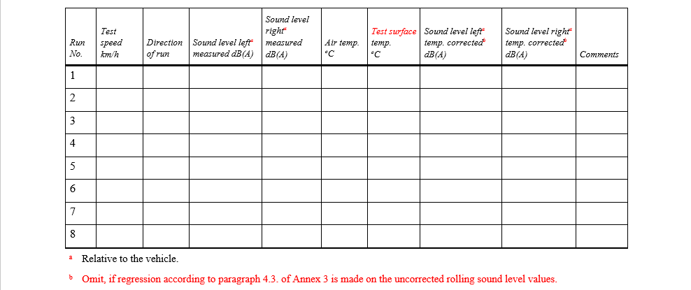
.png) of the average Braking Force Coefficients shall be corrected for effects of temperature as follows:
of the average Braking Force Coefficients shall be corrected for effects of temperature as follows:.png)
.png)
.png)
.png)
.png)
.png)
.png)
.png)
.png)
.png) the arithmetic mean of the average Braking Force Coefficients BFCave,j of N test runs.
the arithmetic mean of the average Braking Force Coefficients BFCave,j of N test runs..png)
.png)
.png)
.png)
.png)
.png)
.png)

.png)
.png)
.png)
.png)
.png)
.png)
.png)
.png) of the measured peak braking force coefficients shall be corrected for the effects of temperature as follows:
of the measured peak braking force coefficients shall be corrected for the effects of temperature as follows:.png)
.png)
.png)
.png)
.png)
.png)
.png)
.png)
.png)
.png)
.png)

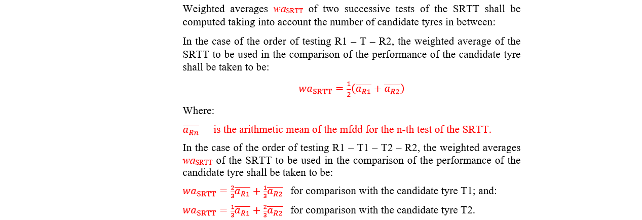
.png) of the mfdd of the tyre Tn and the applicable weighted average waSRTT of the SRTT
of the mfdd of the tyre Tn and the applicable weighted average waSRTT of the SRTT .png)
.png)
.png)
.png)
.png)
.png)
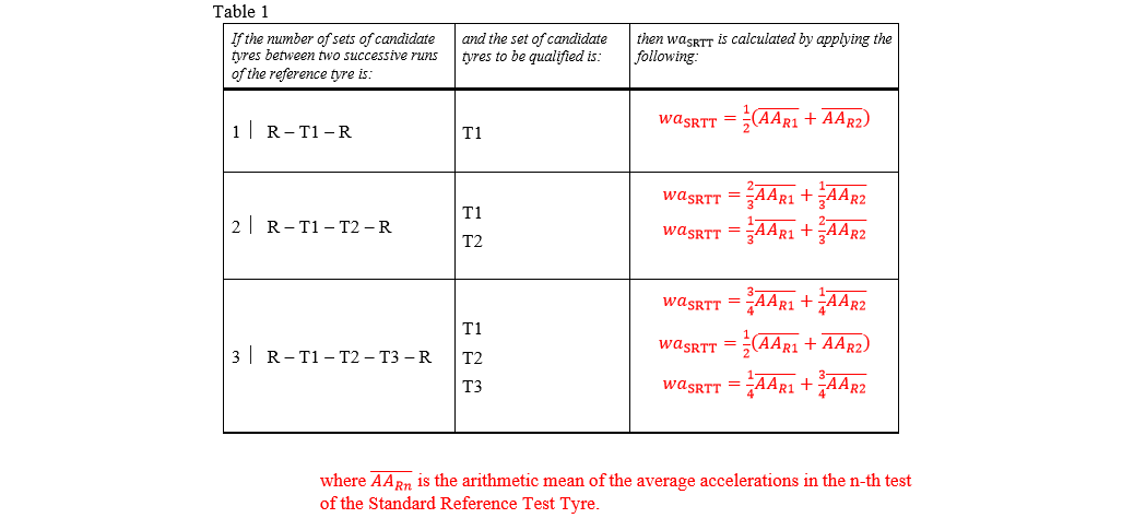

.png)

.png)
.png)
.png)
.png)